Week 11 - Louver/Grille characterization
Problem Description:
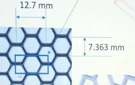
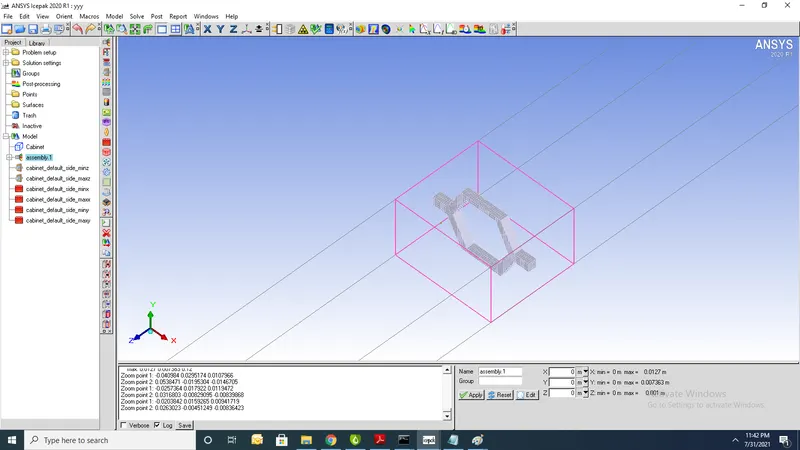
The model includes a cabinet that is 160 mm in length with inlet and outlet openings at the two ends (with cross sectional area of 7.363 mm x 12.7 mm), and four symmetry walls at the other sides. The model also includes a part of the hexa-grille placed at the center of the channel in the streamwise direction, as shown in Figure 9.1: Problem Specification (p. 198). The grille has one full hexagonal hole at the center and four quarter hexagonal holes placed around it. This pattern was selected because it forms a periodic region and is sufficient to calculate the loss coefficient.
Geometry:
1.create cabinet using given grille dimesions
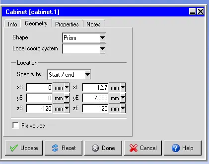
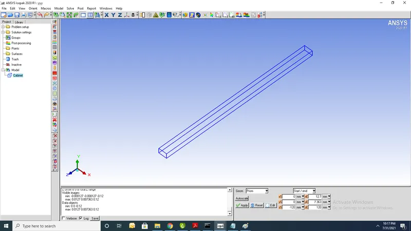
2.Picture of cabinet is shown
3.After creating define properties of grille
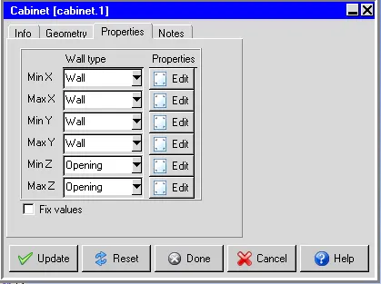
4.for each and every wall define symmetry which means zero gradient for flow and thermal variable
5. Define velocity at inlet zmin in terms of reynolds number
Reynolds Number:

where:
- ρ is the density of the fluid (SI Units: kg/m3)
- u is the flow speed (m/s)
- L is a characteristic linear dimension (m)
- μ is the dynamic viscocity of the fluid (Pa·s or N·s/m2 or kg/(m·s))
- ν is the kinematic viscocity of the fluid (m2/s)
L= Charctersic length for given problem (L=4*(A)/P)
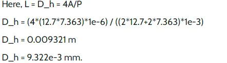
V= Re* kinematic viscosity/charcterstic length
zmin=$Re*1.84e-5/9.322e-3
Here Re=10,50,100,500,1000,2000,3000,4000
4.Create block Define polygon with 13 vertices
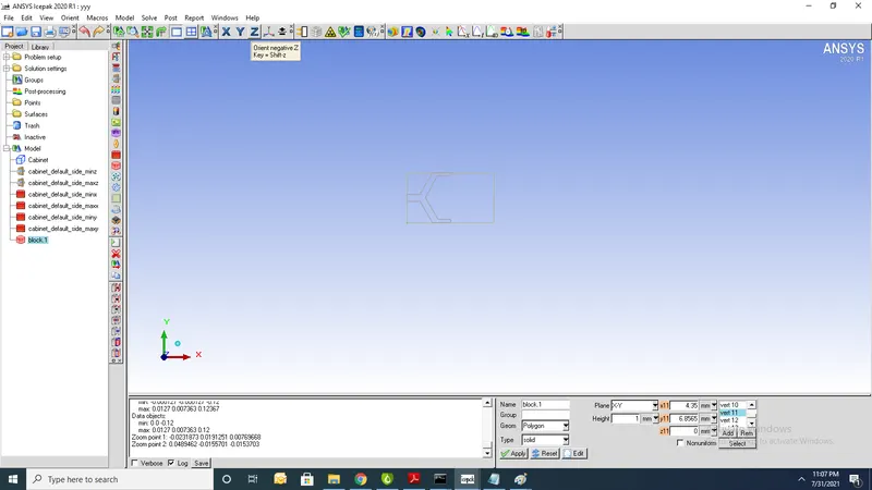
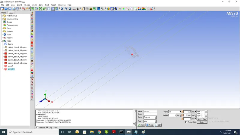
5. Create mirror of block1 to get another griile
Meshing:
1.Create assembly for blocks and mesh separtely (Non-conformal mesh)
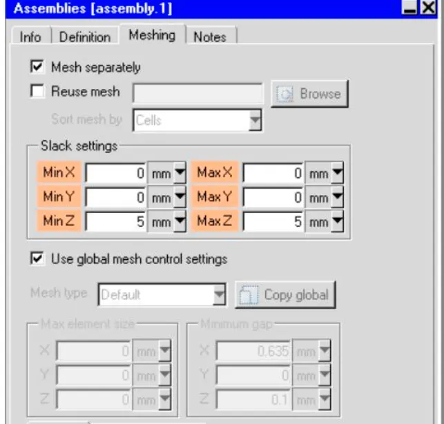
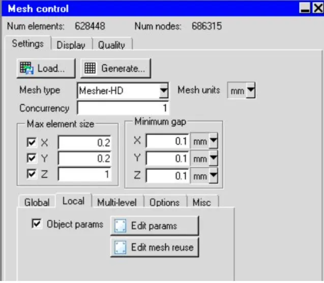
2.For refinement near wall use per object parameters

3.Total Number of nodes= and Total number of components=
Mesh display:
1.Point and normal mesh
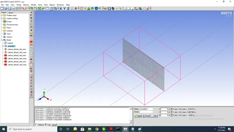
2.Mesh along Y-axis
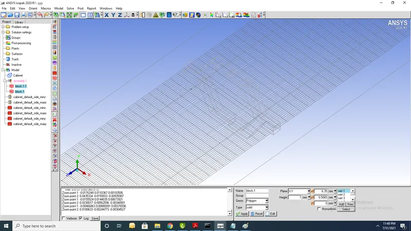
3.Soli-wire mesh of grille
Parametric & optimization :
1.Define Reynolds number( 10 50 100 500 1000 2000 3000 4000)
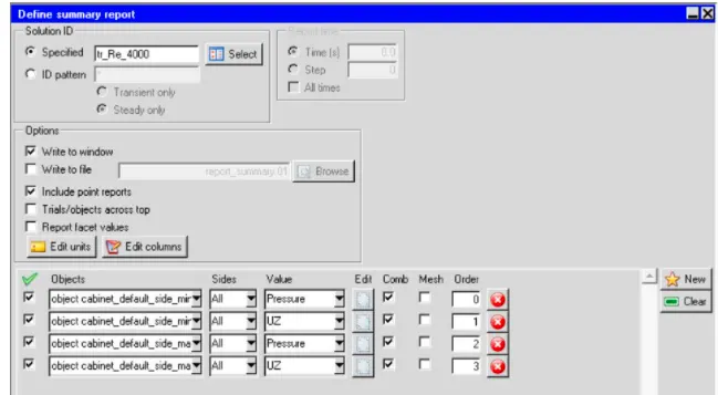
2.Default cabinet side minimum pressure,velocity in Z direction
3.Default cabinet side maximum pressure,velocity in Z direction
4.Select parametric and optimization select primary and secondary functions
5. Primary functions are pressure,velocity
6. secondary functions are dynamic pressure,velocity,losscoefficent
7.Run the trails
1. summary report
2.Primary and secondary functions:
1. Primary functions are pressure,velocity
2. secondary functions are dynamic pressure,velocity,losscoefficent
3.Total pressure inlet=$Pstat_inlet+$pdynamic_inlet
4. Total pressure outlet=$Pstat_outlet+$pdynamic_outlet
5.For K loss coefficent=($Ptot_inlet+$Ptot_outlet)/$pdynamic_outlet
Numerical setup:
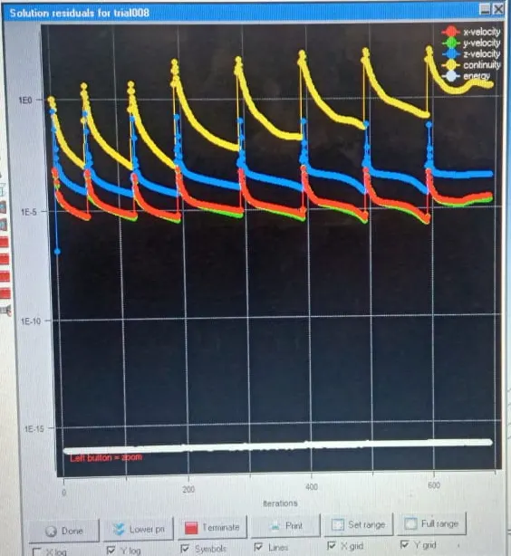
Residuals:
Report:
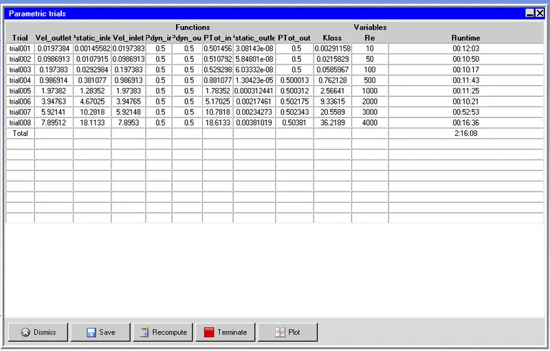
1.From above table it is clear that with increase in Reynolds number increases value of velocity as well as pressure ratio
Primary functions: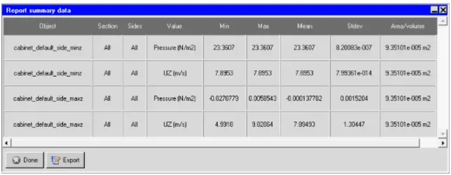
1. Min,Max velocity at opening=7.89m/s and min,max pressure at opening= 23.36N/m^2
2.Max pressure at outlet is 0.0058543(N/m^2) because restrictions and not having free flow movement of air
Loss coefficent:
The loss coefficient (ζ) is a dimensionless number (characteristic coefficient) to calculate the head loss (HL)

1.Plot graph against loss coefficent vs Reynolds number
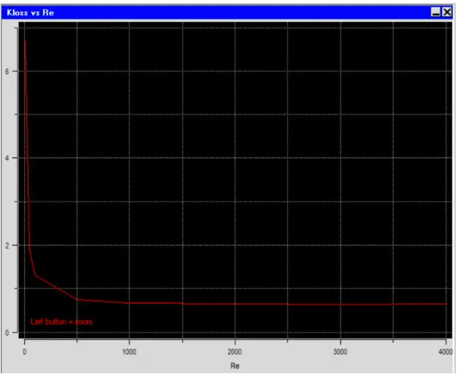
1.Graph shows with increase in Reynolds number loss coefficent decreases
Contours:
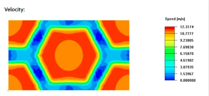
1.Velocity contours of grille charcterization