week-11 Joint creation and Demonstration
AIM:
To simulate spherical, revolute, cylindrical, and translational joints between two rigid bodies and two deformable bodies.
Given Condition:
*CONSTRAINED_EXTRA_NODES needs to be used for rigid bodies.
*CONSTRAINED_NODAL_RIGID_BODY to create joints between rigid and deformable bodies respectively.
Units: kg - mm - ms - KN - GPa
1. Basic Modelling and Parameters:
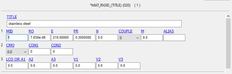
1.1 Rigid Material - MAT 20
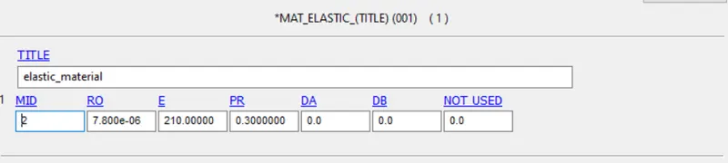
1.2 Deformable Material - MAT 01
1.3 Control Card Definition:
Termination time was defined using *CONTROL_TERMINATION with 5ms as termination time.

Also to have a stable representation of the simulation, *CONTROL_TIMESTEP was defined with LCTM curve defined with 0.1 as the linear value till the termination time. 
2. Spherical Joint Modelling
2.1 Modelling and Meshing
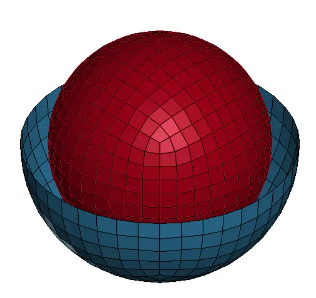
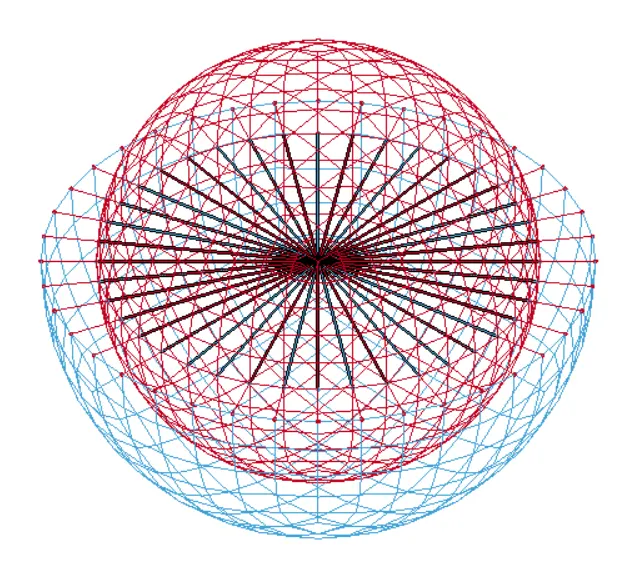
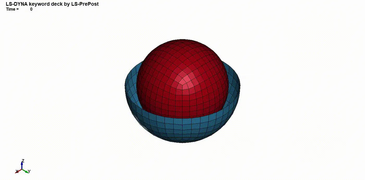
Using the ShapeMesher tool in LS DYNA, a shell sphere and a shell hemisphere were created using the same central node location.
2.2 Constraint Definition
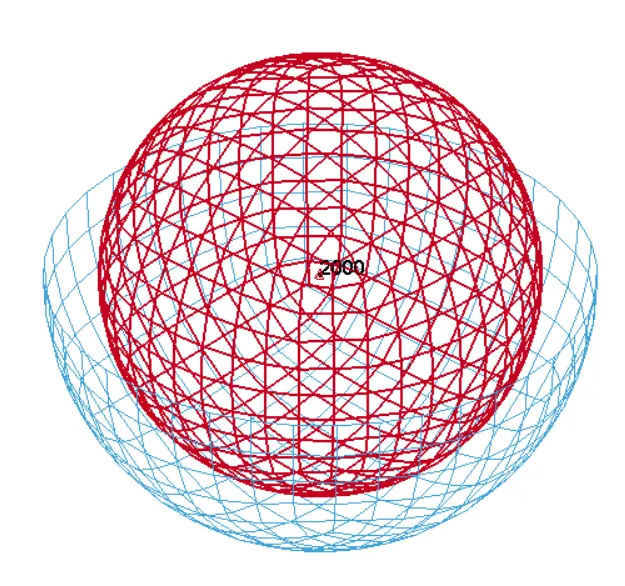
For Rigid material, CONSTRAINED_EXTRA_NODES was utilised, whereas, for deformable material, CONSTRAINED_NODAL_RIGID_BODY was defined.
(a) (b)
Fig: (a) CONSTRAINED_EXTRA_NODES representation (b) CONSTRAINED_NODAL_RIGID_BODY representation
2.2.1 Constraint Joint Definition - Spherical
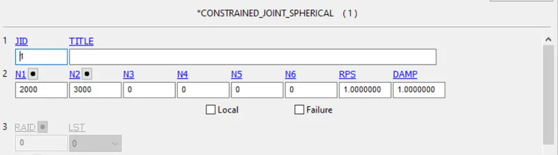
The spherical joint was defined using *CONSTRAINED_JOINT_SPHERICAL, where node N1 - 2000 with and node N2 - 3000 belonged to part one and part 2 respectively.
2.3 Initial Condition Definition
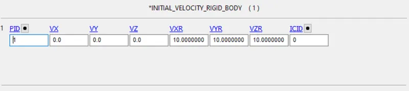
To define the rotational motion for the rigid sphere, *INITIAL_VELOCITY_RIGID_BODY was utilised.
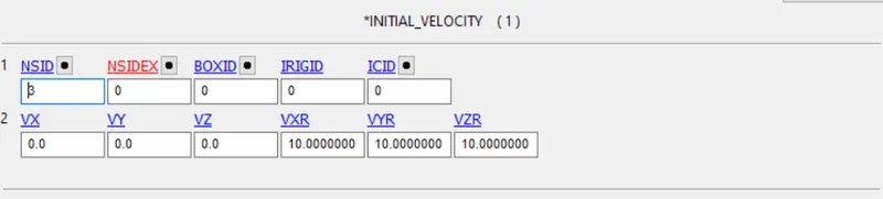
Whereas *INITIAL_VELOCITY card was used to define the motion in the deformable body with NSID defined for the moving part.
Result
3. Revolute Joint Modelling
3.1 Part Modelling
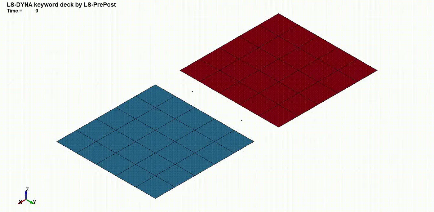
Using ShapeMesher under Mesh tab, two shell plates were modelled keeping a gap between them.
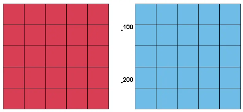
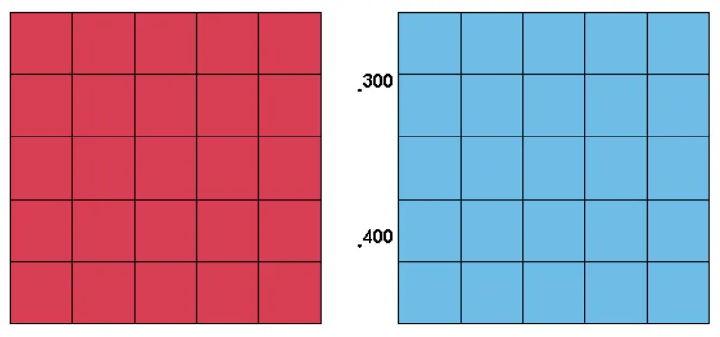
once the model is completed, desired material is assigned to the material.
3.2 Constraint Definition
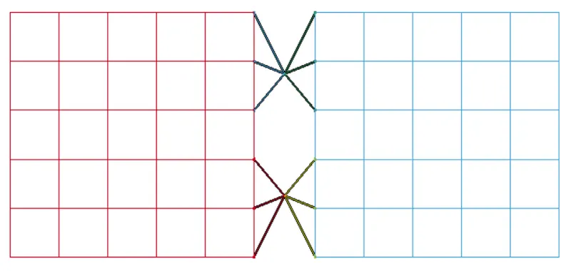
(a) (b)
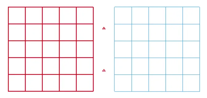
Fig: (a) CONSTRAINED_EXTRA_NODES representation (b) CONSTRAINED_NODAL_RIGID_BODY representation
For Rigid material, CONSTRAINED_EXTRA_NODES was utilised, whereas, for deformable material, CONSTRAINED_NODAL_RIGID_BODY was defined.
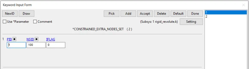

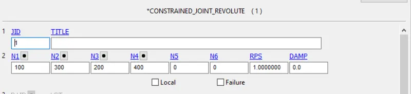
To apply the revolute joint, CONSTRAINED_JOINT_REVOLUTE was utilised
3.3 Boundary Condition Definition
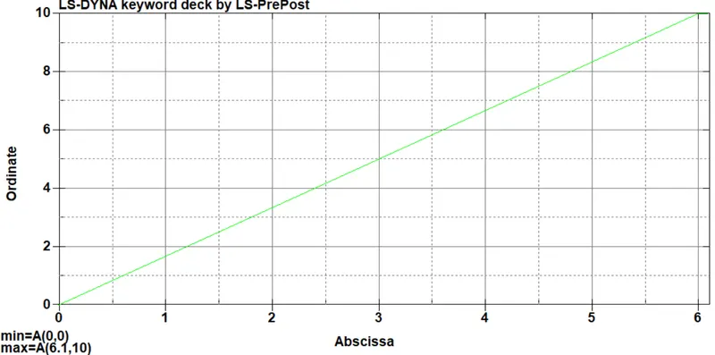
To define the displacement motion to the plate, *BOUNDARY_PRESCRIBED_MOTION_NODES CARD was utilised to define the motion.
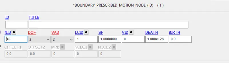
Load Curve define for the prescribed motion:
Result
4. Cylindrical Joint Modelling
4.1 Part Modelling
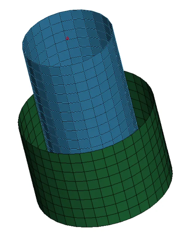
Using ShapeMesher under Mesh tab, two shell tubes were modelled keeping a gap between them.
3.2 Constraint Definition
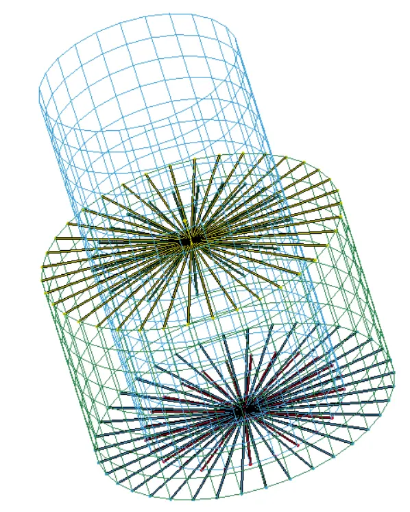
(a) (b)
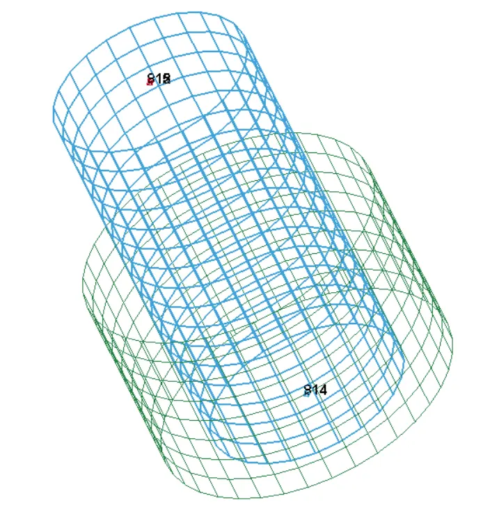
Fig: (a) CONSTRAINED_EXTRA_NODES representation (b) CONSTRAINED_NODAL_RIGID_BODY representation
For Rigid material, CONSTRAINED_EXTRA_NODES was utilised, whereas, for deformable material, CONSTRAINED_NODAL_RIGID_BODY was defined.
3.2.1 Constraint Joint Definition - Cylindrical
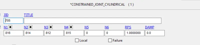
The cylindrical joint was defined using *CONSTRAINED_JOINT_CYLINDRICAL, where node N1 - 816, N3 - 812 with and node N2 - 814 , N4 - 815 belonged to part 1 and part 2 respectively.
4.3 Initial Condition Definition
To define the rotational motion for the rigid cylinder, *INITIAL_VELOCITY_RIGID_BODY was utilised.
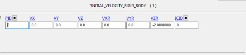
Whereas *INITIAL_VELOCITY card was used to define the motion in the deformable body with NSID defined for the moving part.

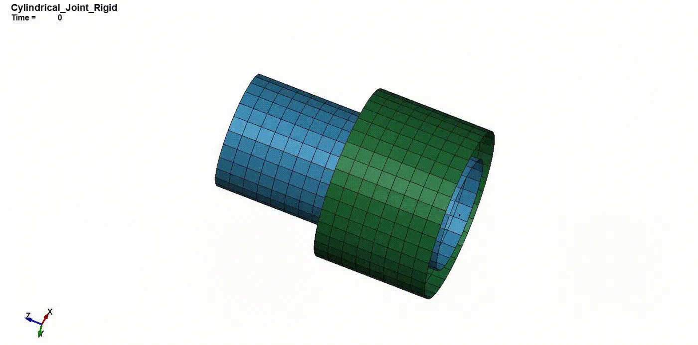
Result
5. Translational Joint Modelling
5.1 Part Modelling
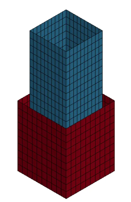
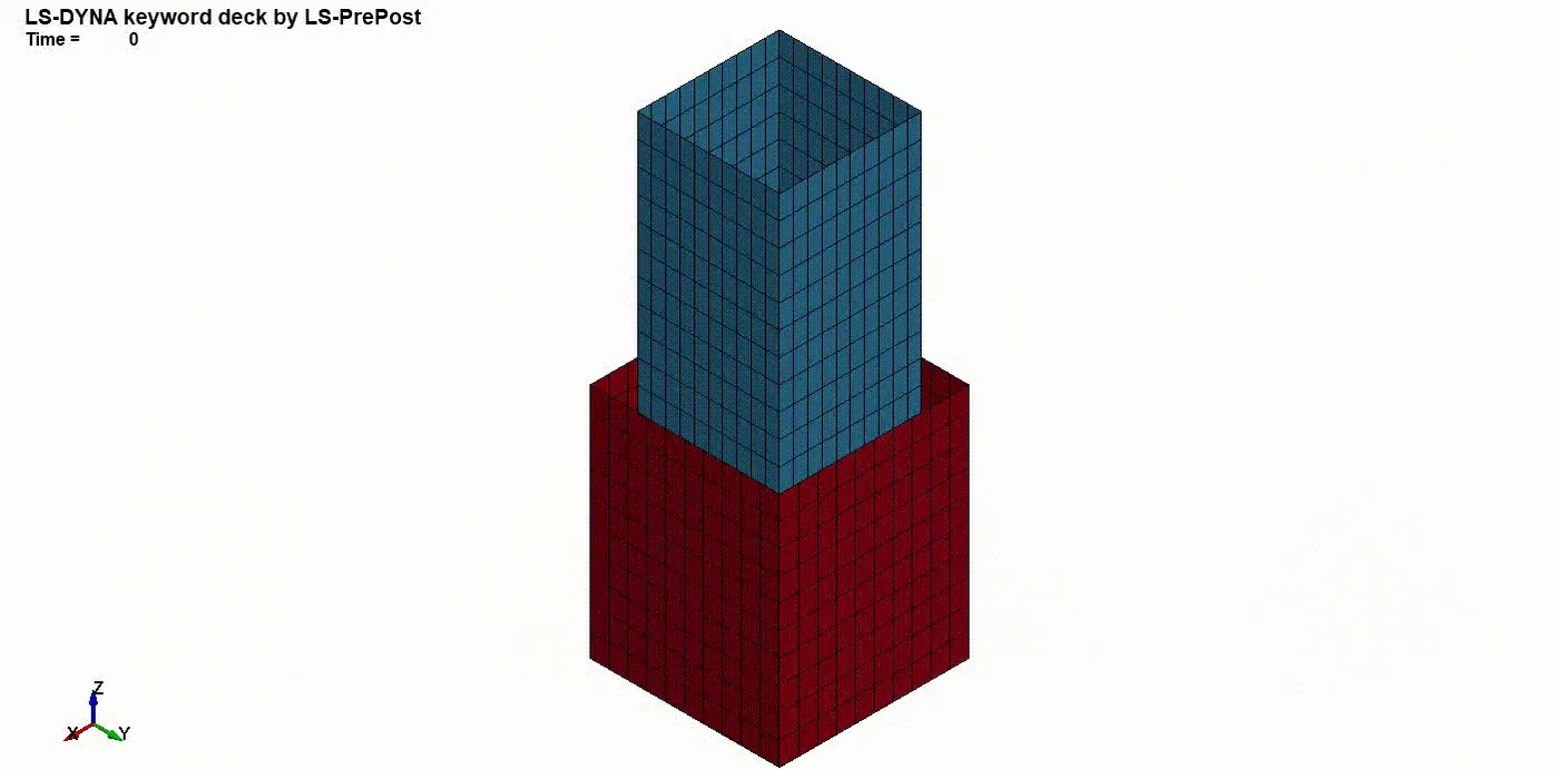
Using ShapeMesher under Mesh tab, two shell cuboidal tubes were modelled keeping a gap between them.
5.2 Constraint Definition
(a) (b)
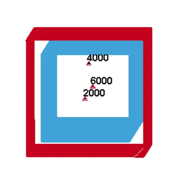
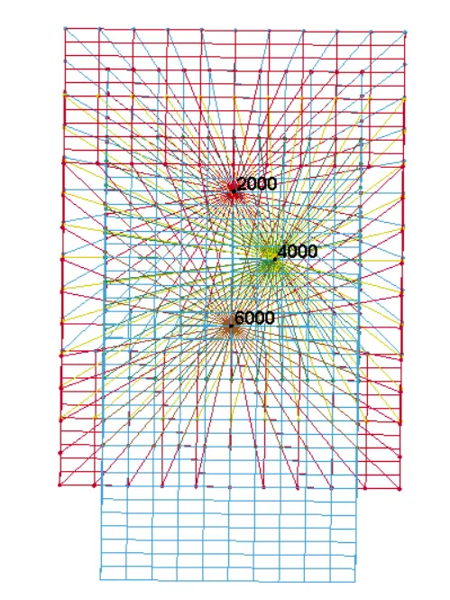
Fig: (a) CONSTRAINED_EXTRA_NODES representation (b) CONSTRAINED_NODAL_RIGID_BODY representation
Where nodes 2000 and 6000 are colinear and 4000 is placed slightly off axis to control the rotational motion in translational joint.
For Rigid material, CONSTRAINED_EXTRA_NODES was utilised, whereas, for deformable material, CONSTRAINED_NODAL_RIGID_BODY was defined.
5.2.1 Constraint Joint Definition - Translational
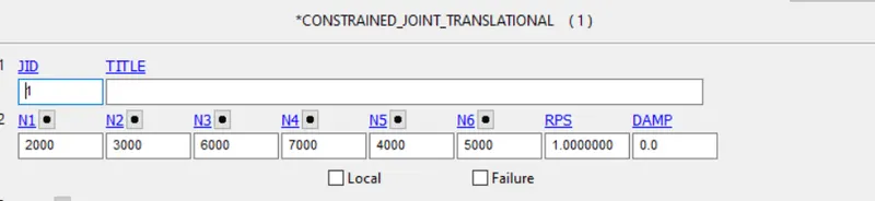
The translational joint was defined using *CONSTRAINED_JOINT_TRANSLATIONAL, where nodes 2000,3000,6000,7000 controlled the translational motion whereas nodes 4000 and 5000 were modelled off-axis to control the rotational motion and defined at the end(N5 and N6) respectively.
Result
CONCLUSION
Considering Rigid and Deformable bodies, Spherical, Revolute, Cylindrical and Translational joints are simulated and the resultant animation is presented.
- Spherical Joint - Rotational DOF was defined between two nodes to obtain a Spherical joint between two parts.
- Revolute Joint - Only one Rotational DOF is allowed in this joint where the axis of rotation is defined using a pare of node co-incident on each other.
- Cylindrical Joint - Rotational and Translational DOF is allowed in one axis when this joint is defined.
- Translational Joint - Only translational DOF in one axis is allowed. A pair of node is defined away from the axis of translational motion to prevent the rotational motion of the body.