week-11 Joint creation and Demonstration
AIM: Using the manual (*CONSTRAINED_JOINT keyword) demonstrate spherical, revolute, cylindrical, and translational joints between two rigid bodies and two deformable bodies.
PROCEDURE:
Spherical Joint.
- For that we will use the MESH>SHAPE MESHER and create the twol elements as shown:
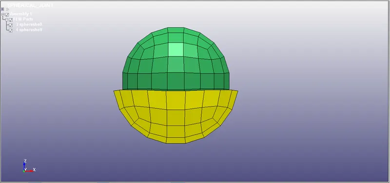
- Now will assign the material to it.
- We will use the Elastic and a rigid material for the join connection.
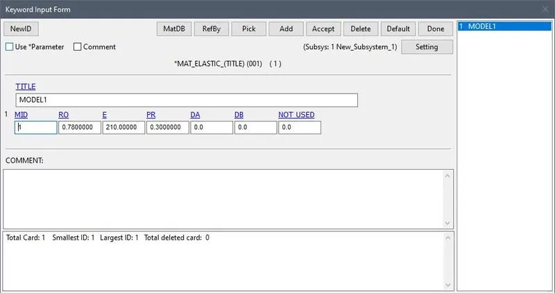
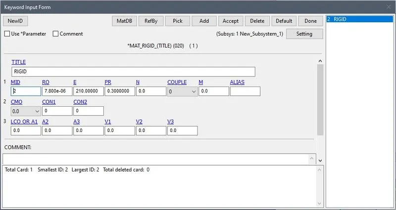
- SECTION:
- We have to create Shell section.
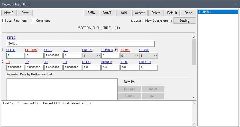
- After that we will assign it to the part.
- Now to create a joint first we will constrained the nodes.
- First we will create the nodes. Element Tools>Node Editing>Create
- Now after craeting the nodes we will contrained with the help of *CONSTRAINED_EXTRA_NODES
- 300 for part 1 and 301 for part 2
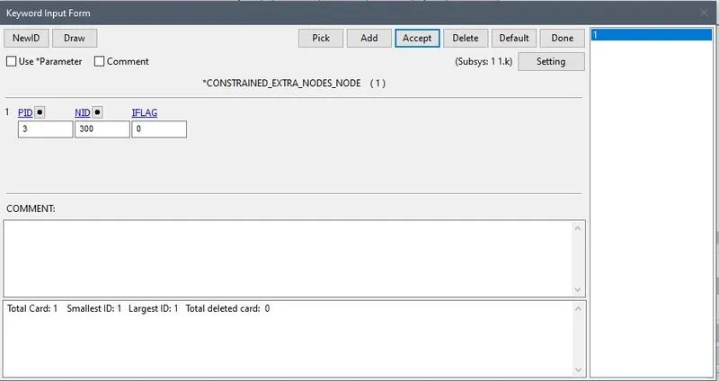
- Same as above for part 2.
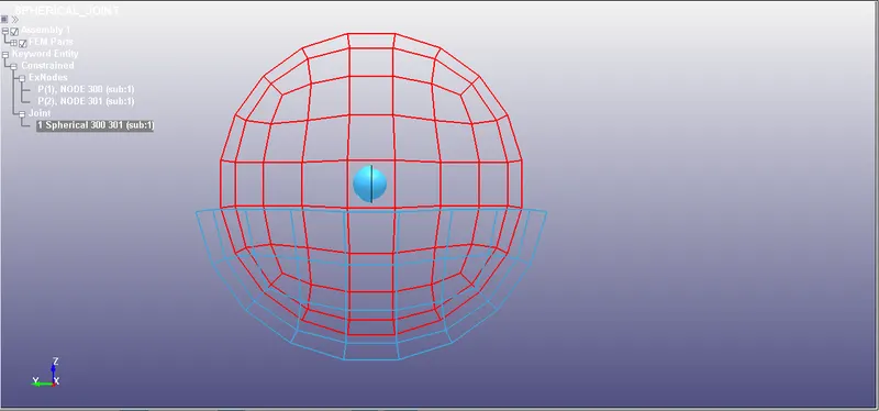
- The spherical joint is created using *CONSTRAINED_JOINT_SPHERICAL card with one node pair i.e node N1 is 305 for part 1and Node N2 is 306 for part 2.
- Termination:
- TIMESTEP
D3PLOT
JOINT BETWEEN TWO DEFORMABLE SPHERE BODY
- Create a ELASTIC MATERIAL and assign it to the part.
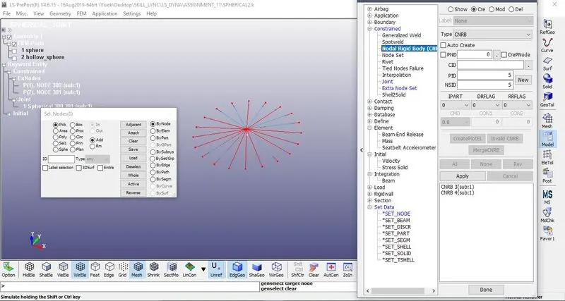
- After that create a 4 nodes. Now, go to Create Entity>Constrained>Nodal Rigid Body(CNRB)>Create. Toggle off the CrePNode option which will diable the creation of PNODE at the mass center of selected nodes.
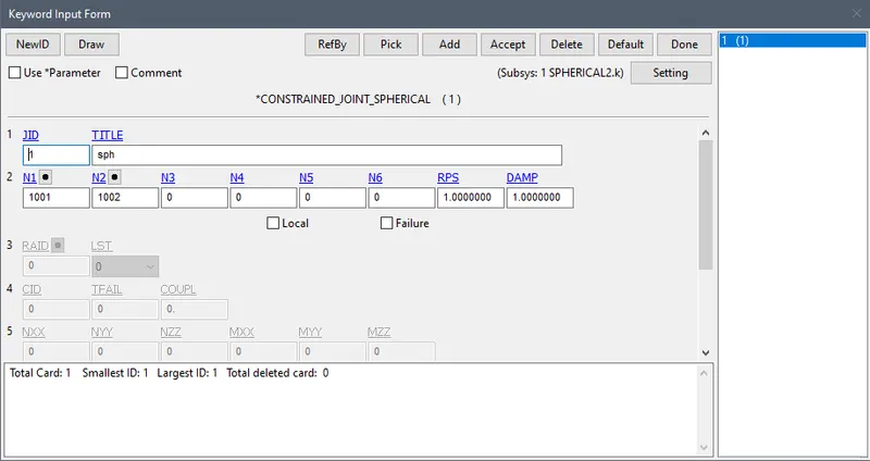
- Now aftet that spherical joint is defined by using *CONSTRAINED_JOINT keyword.
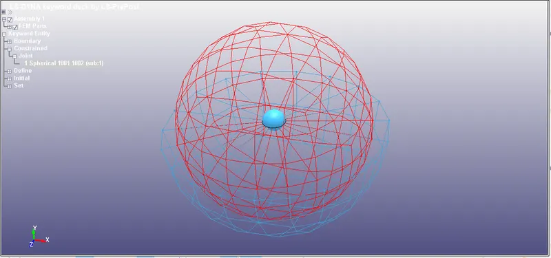
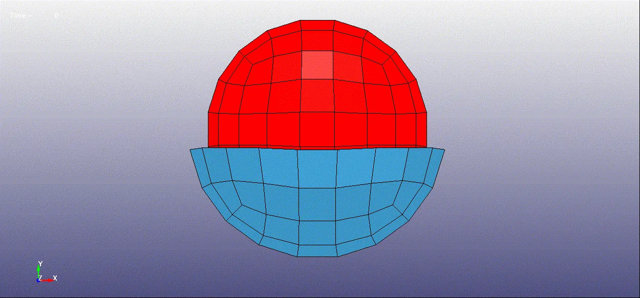
- Assign the velocity to the the CNRB1 and run the simulation.
REVOLUTE JOINT:
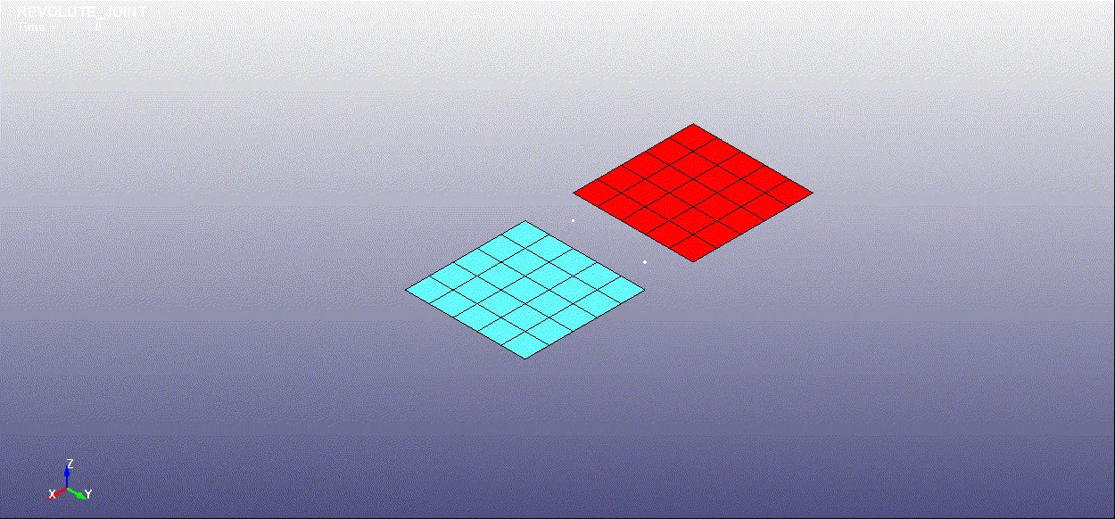
- Open LS-PrePost, using options under Element and Mesh>Shape Mesher> Entity>4N Shell, create two parts as shown:
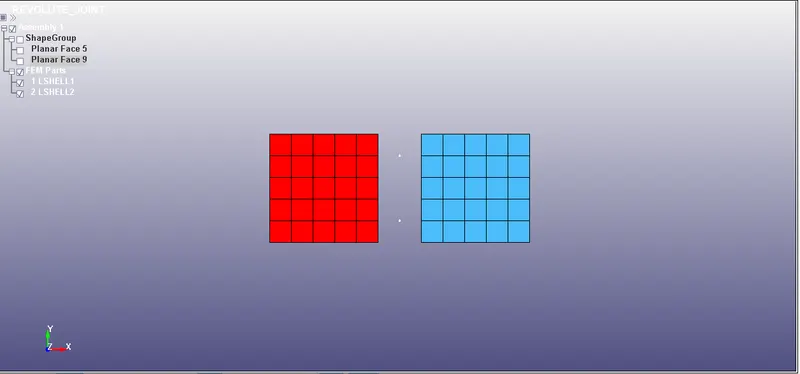
- Also the 4 nodes 301,302,303,304 are created with the same process. Shown with the white dots.
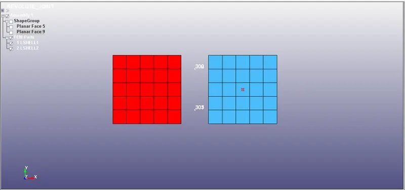
- Create new node sets, where nodes 300 and 301 belong to one node-set, and nodes 302 and 303 belong to another node-set. shows the node assignment for *SET_NODE_LIST keyword. The node sets can be created through Create Entity>Set Data>*SET_NODE>Create option.
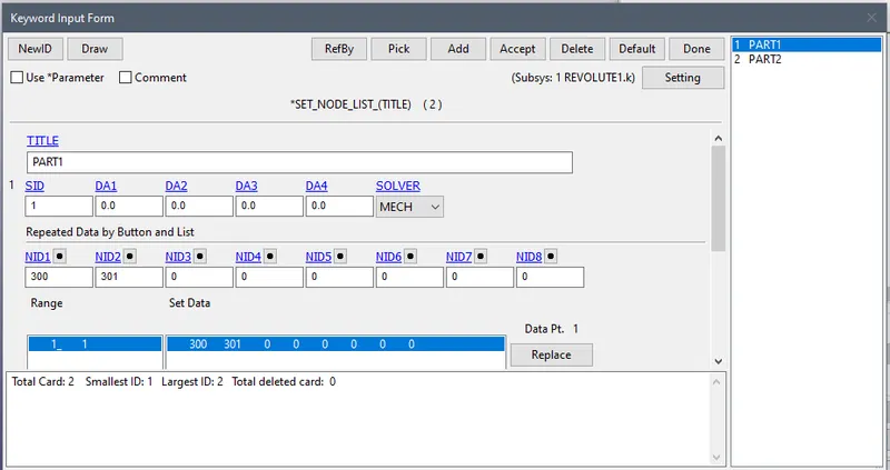
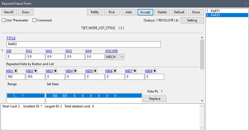
- These newly created nodes are in the space and do not belong to any of the parts now. So, for associating these nodes with part 1 and part 2, *CONSTRAINED_EXTRA_NODES_SET node 300 and 301 belong to part 1 and nodes 302 and 303 belong to part 2.
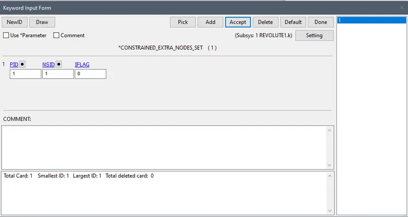
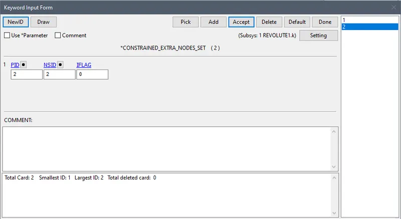
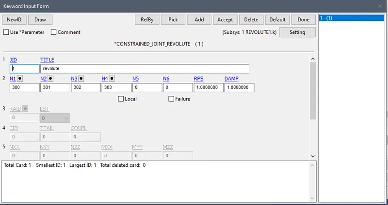
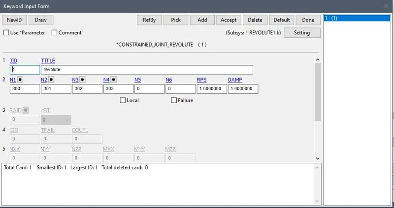
- Now, the revolute joint is defined by using *CONSTRAINED_JOINT keyword. Four nodes should be defined to create a revolute joint. N1 and N3 belong to body 1 and N2 and N4 belong to body 2. So, N1=300, N2=301, N3=302, and N4=303 are defined in the keyword.
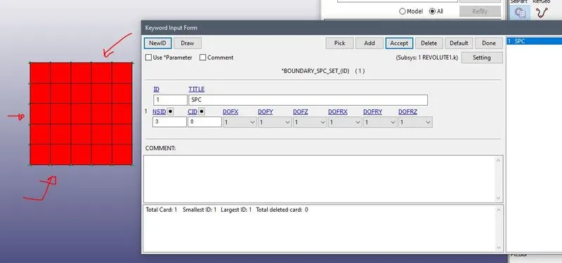
- Single point constraint(SPC) is also used to fix part 1 at its position. Several nodes on the edge of part 1 are selected and assigned *BOUNDARY_SPC.
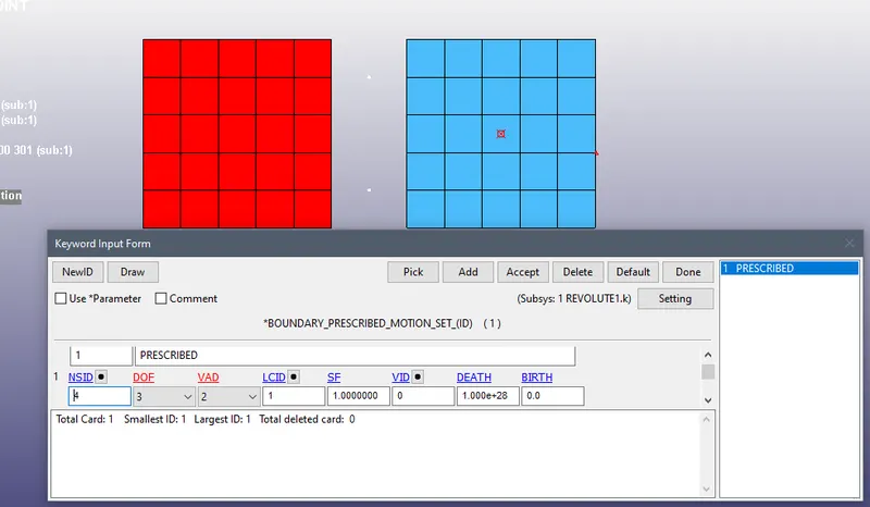
- Now, to make this revolute joint work, few boundary conditions are essential. So, a displacement along a positive Z direction is applied to one of the nodes on part 2. This is defined by *BOUNDARY_PRESCRIBED_MOTION keyword. The z-translational DOF is kept free by assigning DOF=3 in the keyword.
CURvE:
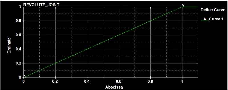
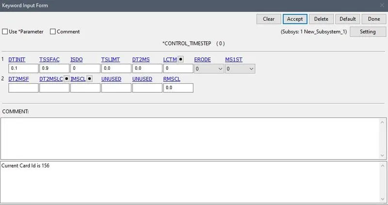
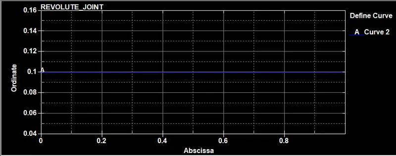
- *CONTROL_TIMESTEP card is used and a load curve shown in figure 1.11 is assigned through LCTM option. The time step calculated by the solver for these rigid bodies and this mesh size is large enough and hence for more stability we use smaller time steps for explicit analysis..
D3PLOT
FOR DEFORMABLE BODIES:
- Create a ELASTIC MATERIAL and assign it to the part.
- After that create a 4 nodes. Now, go to Create Entity>Constrained>Nodal Rigid Body(CNRB)>Create. Toggle off the CrePNode option which will diable the creation of PNODE at the mass center of selected nodes.
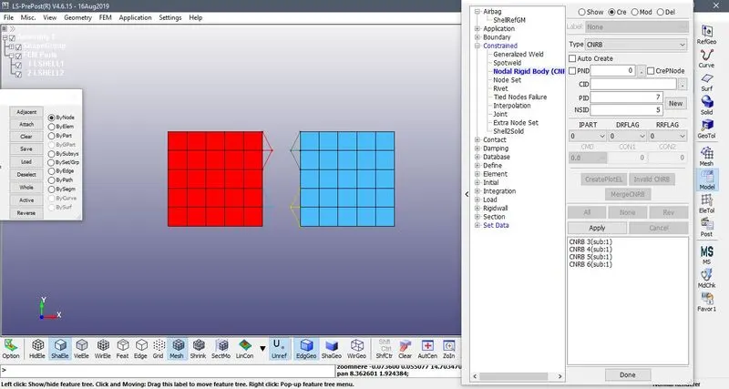
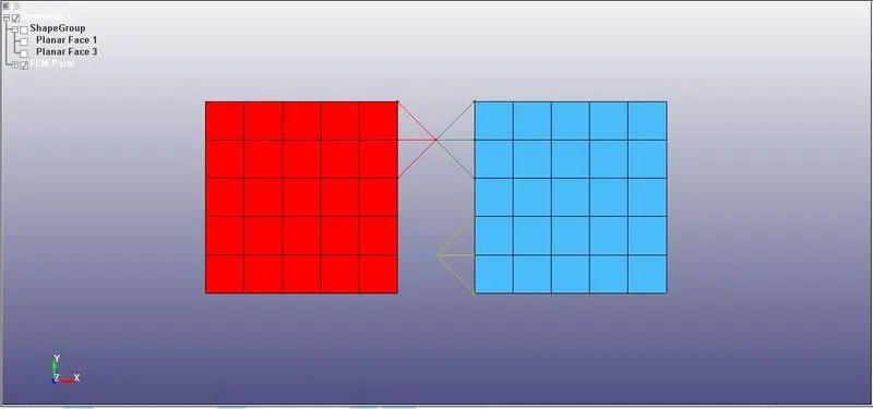
- Now, according to the condition for revolute joint nodes should coincide. This can be done by Element Tools>Transform>Translate>Move option.
- Revolute joint is defined by using *CONSTRAINED_JOINT keyword. Four nodes should be defined to create a revolute joint. N1 and N3 belong to body 1 and N2 and N4 belong to body
D3PLOT
CYLINDRICAL JOINT:
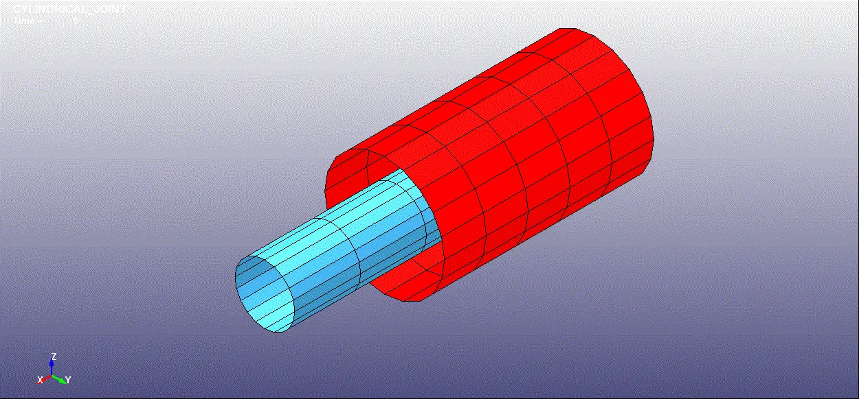
- We will create two cylinder with the help of a MESH>SHAPE MESHER
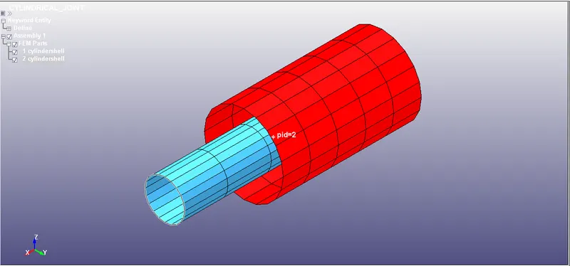
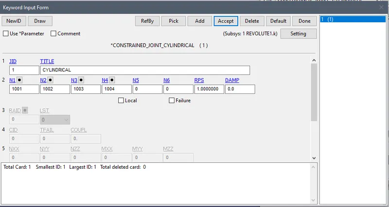
- Now we willl create a 4 nodes 1001,1002,1003,1004 for the joints.
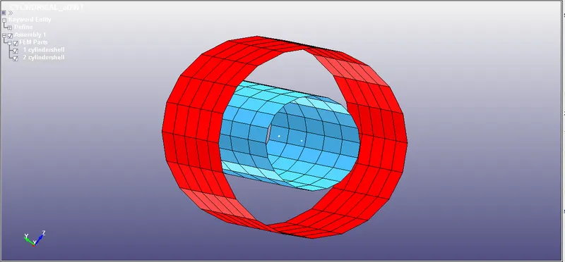
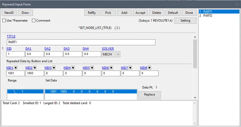
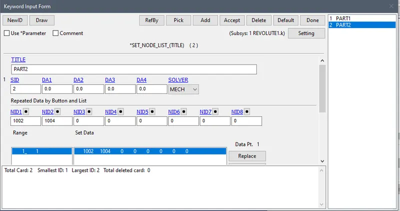
- Now we will create node set list for 1001 and 1003 in one set and 1002 and 1004 in another set
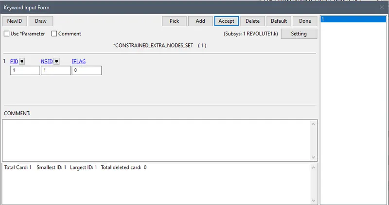
- Now will contrained this node set to the part
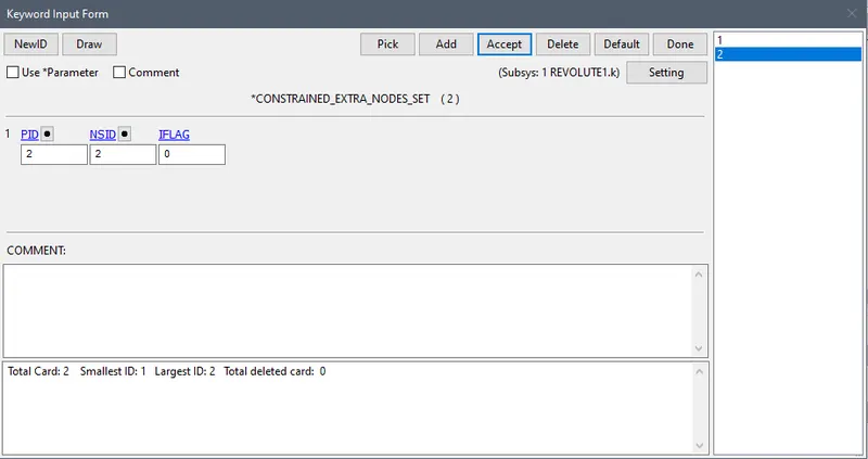
- Now we will create the cylindrical joint,
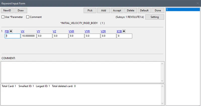
- Now we will assign the intial velocity in X direction.
D3PLOT
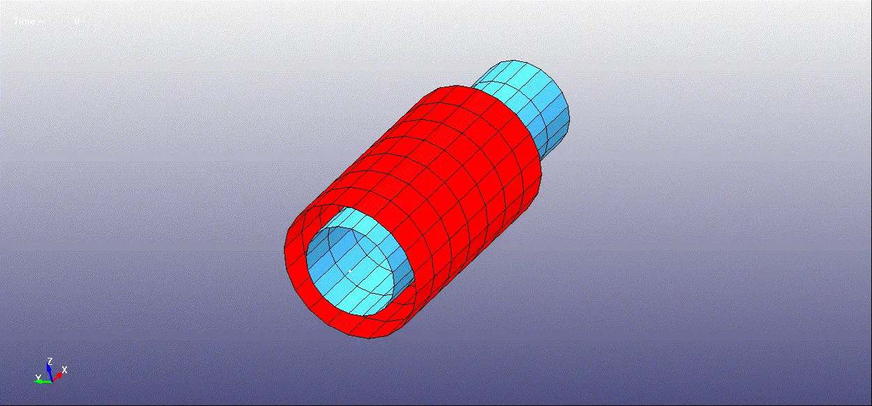
JOINT BETWEEN TWO DEFORMABLE CYLINDRICAL BODY
- Create a ELASTIC MATERIAL and assign it to the part.
- After that create a 4 nodes. Now, go to Create Entity>Constrained>Nodal Rigid Body(CNRB)>Create. Toggle off the CrePNode option which will diable the creation of PNODE at the mass center of selected nodes.
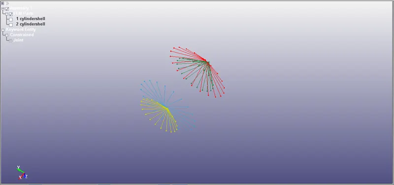
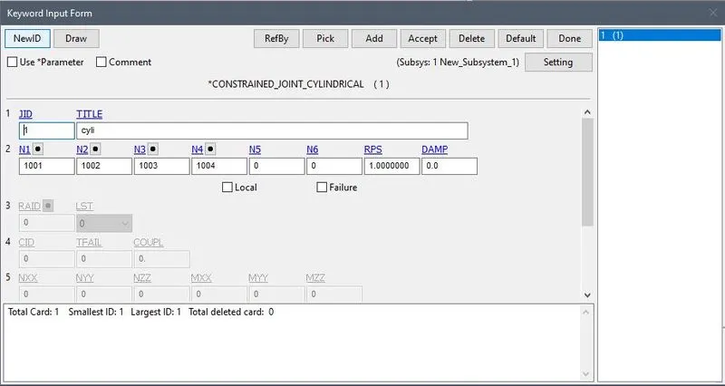
- Cylindrical joint is defined by using *CONSTRAINED_JOINT keyword. Four nodes should be defined to create for cylindrical joint.
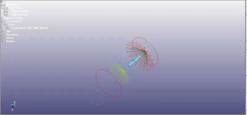
- Assign the velocity VX=10 to the the CNRB1 and run the simulation..
TRANSLATIONAL JOINT
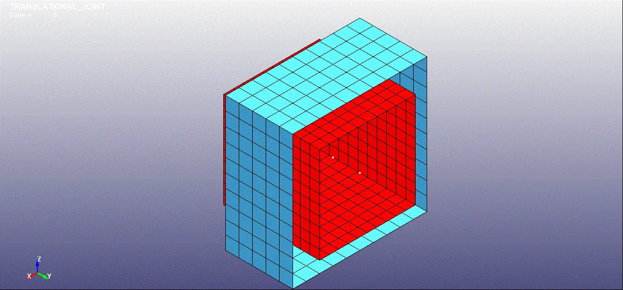
- We will create two box with the help of a MESH>SHAPE MESHER
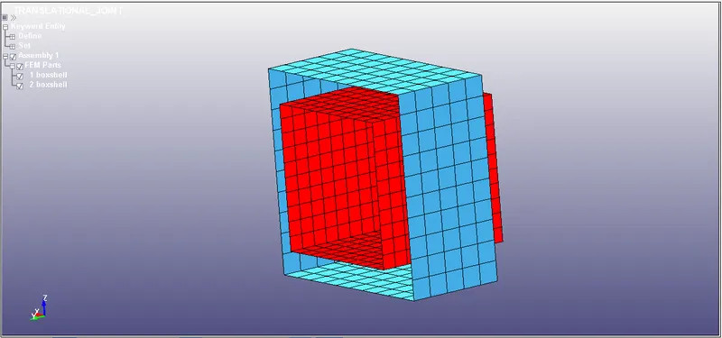
- Now we will create node set list for 1001,1002, 1003 ,1004 , 1005 and 1006.
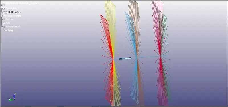
- For translational joint we need 6 nodes 4 linear and 2 slightly below.
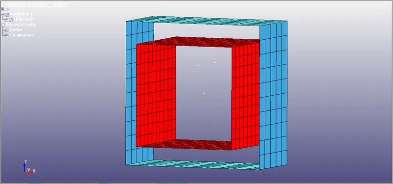
- Now we will create a node set group.
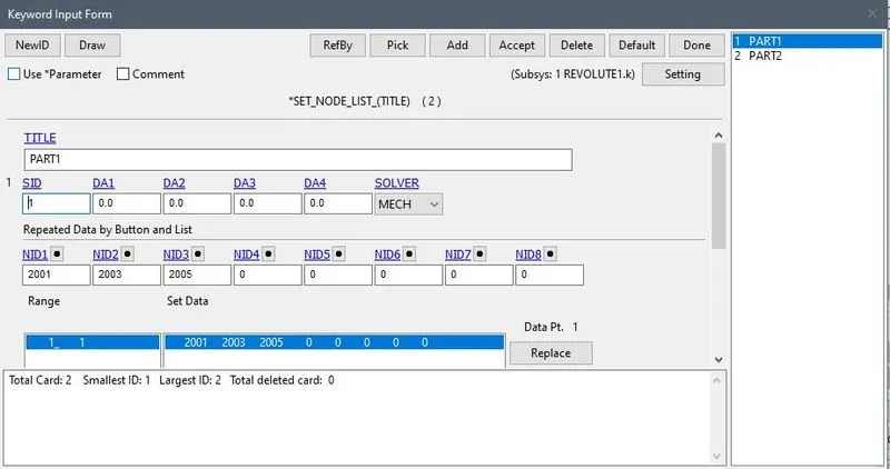
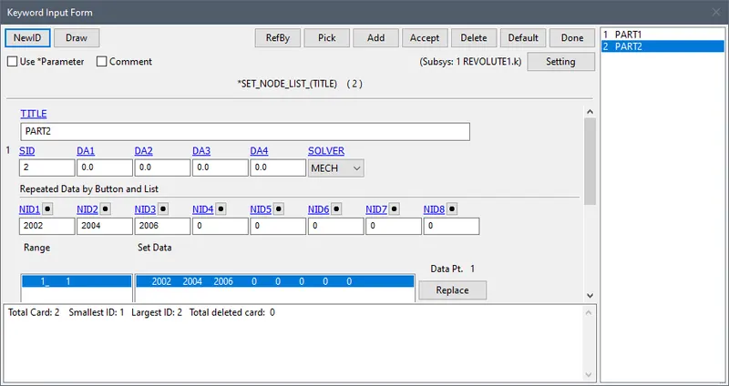
- Now will contrained this node set to the part
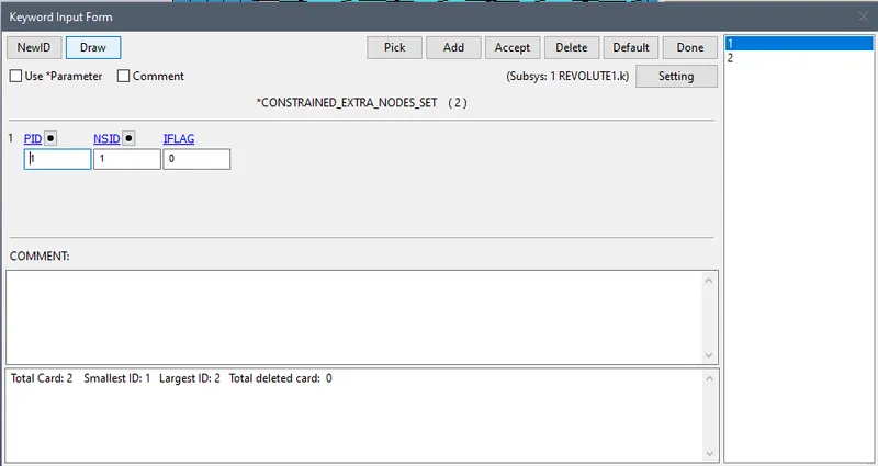
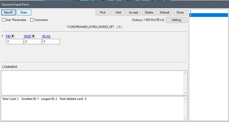
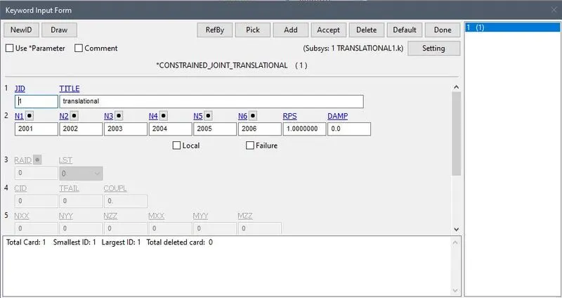
- Creating Translational joint.
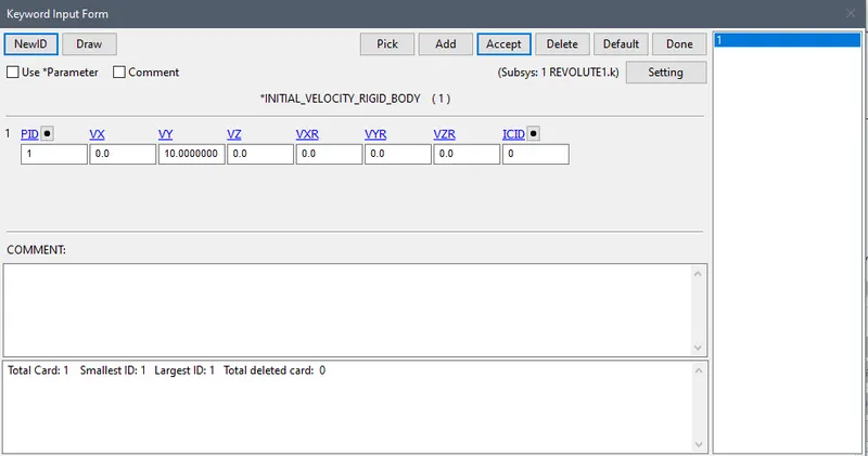
- The initial velocity of 10mm/ms is assigned to the part 1 in the Y-axis.The value of Initial time step size (DTINIT) is set as 0.01 ms.
D3PLOT
JOINT BETWEEN TWO DEFORMABLE TRANSLATIONAL BODY
- Create a ELASTIC MATERIAL and assign it to the part.
- After that create a 4 nodes. Now, go to Create Entity>Constrained>Nodal Rigid Body(CNRB)>Create. Toggle off the CrePNode option which will diable the creation of PNODE at the mass center of selected nodes.
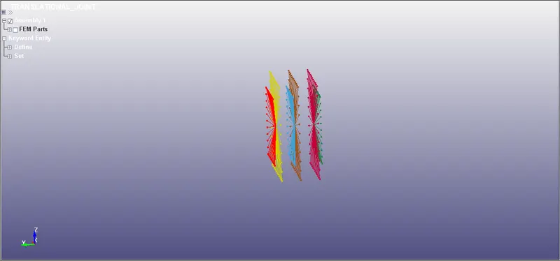
- Translational joint is defined by using *CONSTRAINED_JOINT keyword. Six nodes should be defined to create for translational joint.
- Assign the velocity VY=-10 to the the CNRB1 and run the simulation..
CONCLUSION:
- The above exercise helps us understand the procedure of creating 4 different types of joint for both rigid bodies and deformable bodies using Constrained_Extra_Nodes and CNRBs respectively. Other types of joints can also be explored using the method of extra nodes and CNR