Week 11 - Final project
Development of a Door Trim panel
Aim;
To Creation of CAD model considering the following inputs as like in OEM and tier1 companies
- a) Class A surface
- b) Nominal thickness: Refer to master sections
- c) Attachment strategy :
to create an attachment strategy for the door panel complete work.
Use Pushpin with Dog house for Lower substrate – Door panel attachment
Use heat stakes for the part to part attachment
Software required:
CATIA_V5 R21
Procedure:
1. Armrest
i. armrest 1
ii. armrest 2
i. Armrest 1:
Class A surface:
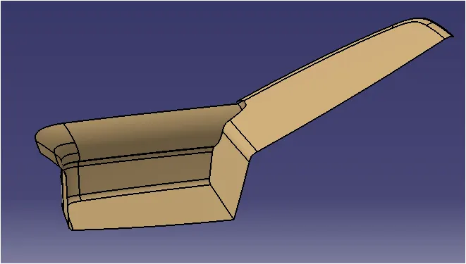
- initially, we have only had a class-A surface.
- This class is given by the styling surface team. we need to create a class B surface by using a class-A surface. Next slide further we discussed in detail.
class B surface:
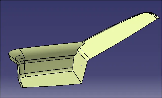
This is a class B surface. This surface is offset for a 2.5mm distance. ensure that we need only outside boundaries in that class b surface
Class C surface:
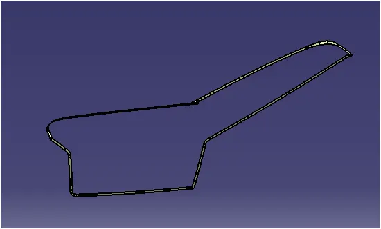
In this class C surface created by using the class-A surface. actually, we sweep at A surface outside the boundaries. Along with tooling direction and guide curves.
CLOSED VOLUME ARMREST 1:
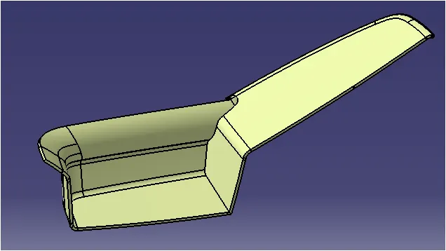
This is closed volume by using class A, class B, and class C surfaces.
FLANGE WITH ARMREST 1:
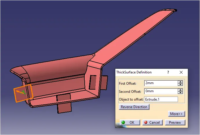
In ARMREST 1 the flange thickness is 2mm. Once it's done after we go with union trim, in this case, what are all need or don’t need we selected on that union trim operation.
FLANGE DRAFTED IN ARM REST 1:
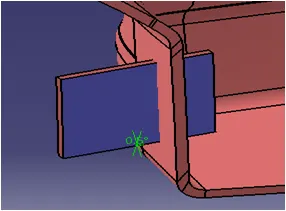
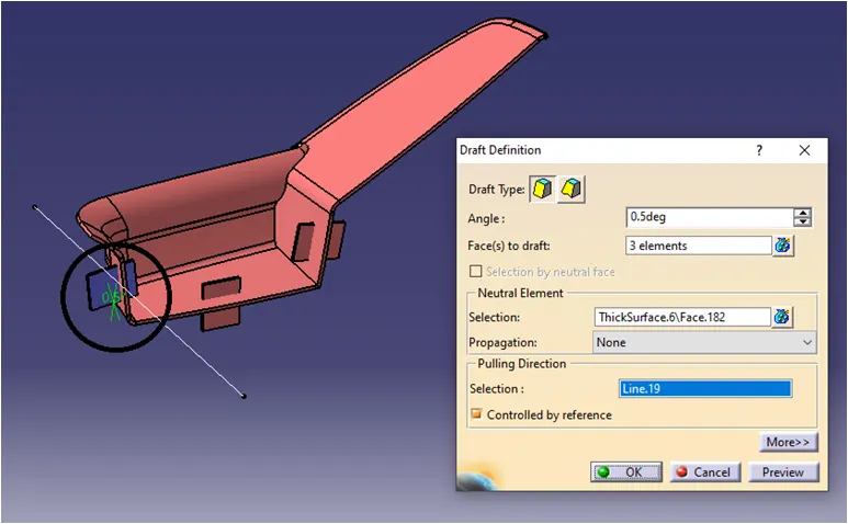
In that draft we selecting the faces to draft, we applying neutral element and pulling direction also.
HEAT STAKE ARMREST 1:
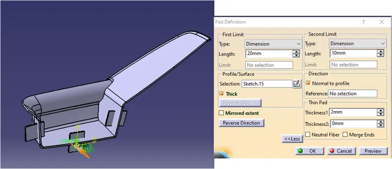
In the heat, the stake comes to the middle of the flange. Then here also we applying same union trim operation.
NOTE:
AS WE KNOW EVERY PARTS OR FEATURE THEY HAVE A DIFFERENT TOOLING DIRECTION AND SOME PARTS OR FEATURES HAVE A SIDE CORE AXIS.SO ACTUALLY WHEN WE NEED TO APPLY DRAFTED OR DRAFT ANALYSIS IN A PARTICULAR PART OR FUTURE WE SHOULD APPLY THEIR TOOLING DIRECTION AND SIDE CORE AXIS.
ARMREST 1 TOOLING AXIS:
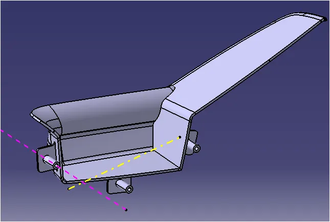
There are two tooling directions. One is the main tooling direction which is yellow in color and another one is the heat stake tooling direction which is pink in color.
TOOLING AXIS:
- Tooling Axis:
Is the axis in which both the cavity and core can be removed from the mold easily without any disturbing bodies or the resisting bodies.
-
Side core axis:
this also the same work method of the tooling axis but few drafting rules are modified by using of side core axis usage is while working on the tooling axis some other features are cant generate the drafting tool, so that time we using to get drafting tool by using side core axis.
DRAFTING ANALYSIS:
1.
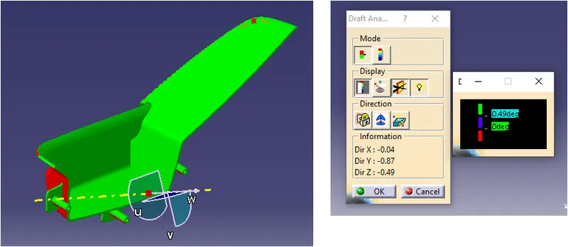
where is the green color showing in that place more than 0.49 degrees, where is the red color showing in that place below 0 degrees, and blue color showing places is 0 degrees.
2.
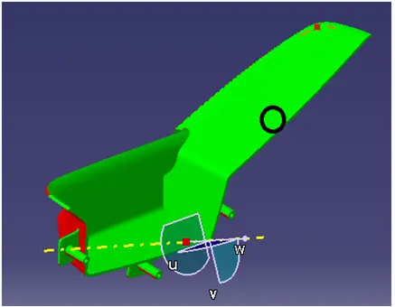
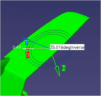
The circle is showing the analysis area The value is 25.016 deg inverse. It means that the surface having more than 0.49 degrees that’s why it's showing green surface color.
3.
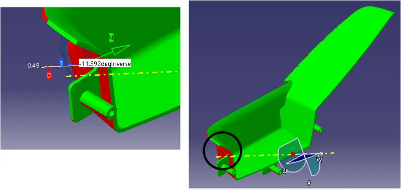
Here we saw in the measurement of angles variations. Which red surface is showing -11.392 degrees, actually I already I mention that is which surfaces are having red color in that particular surfaces having below 0 degrees.
SOLID PART ARMREST 1:
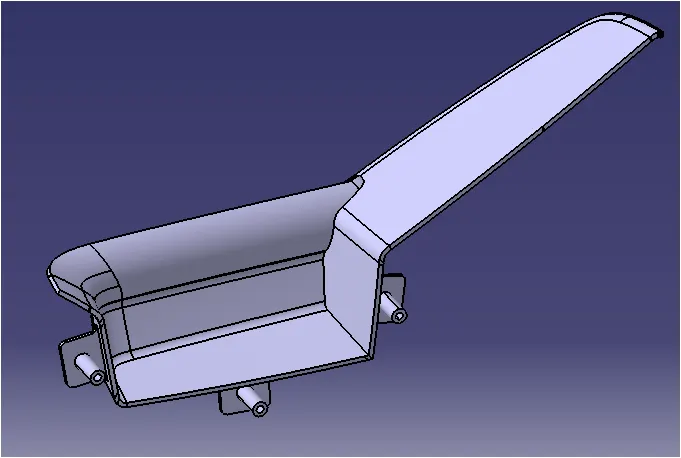
ii. Armrest 2:
CLASS A SURFACE:
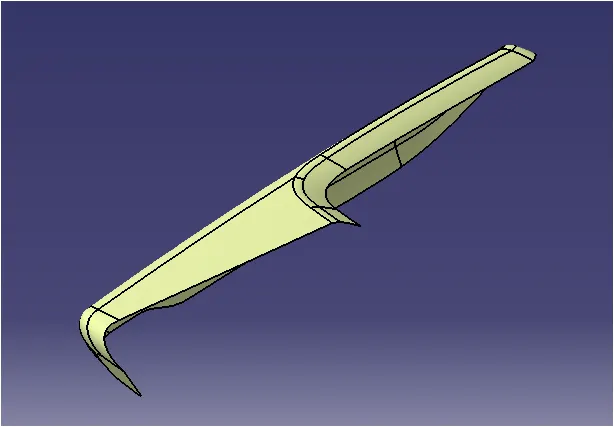
This class is given by the styling surface team. we need to create a class B surface by using class-A surface. Next slide further we discussed in detail.
CLASS B SURFACE:
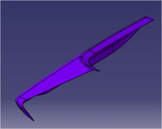
This is a class B surface. This surface is offset for a 2.5mm distance. ensure that we need only outside boundaries in that class b surface.
CLASS C SURFACE:
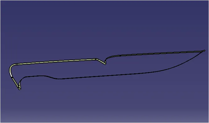
In this class C surface created by using the class-A surface. actually, we sweep at A surface outside the boundaries. Along with tooling direction and guide curves.
CLOSED VOLUME OF ARM REST 2:
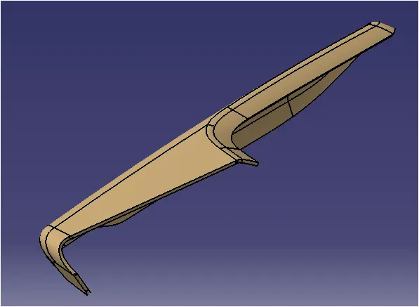
This is closed volume by using class A, class B, and class C surfaces.
FLANGE WITH ARMREST 2:
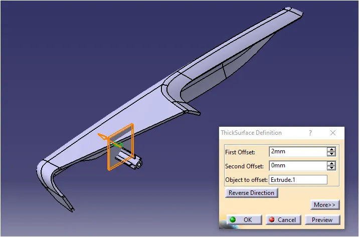
In ARMREST 2 the flange thickness is 2mm. Once it's done after we go with union trim, in this case, what are all need or don’t need we selected on that union trim operation.
UNION TRIM OPERATION :
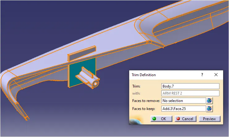
The union trim tool is used to what are the faces we need it that are kept it or else what are faces we don’t need it that also we must select that parts. which aqua color is faces to keep and another one is pink color is faces to remove.
DRAFT FOR FLANGE:
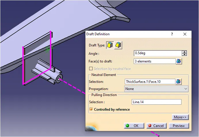
The draft angle should be given 0.5 degrees. we applying neutral elements and pulling direction also.
HEAT STAKE WITH ARM REST 2:
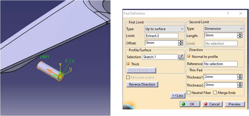
The heat stake should be placed on the flange. The dimension of outer is diameter 7.5mm
DRAFT FOR HEAT STAKE:
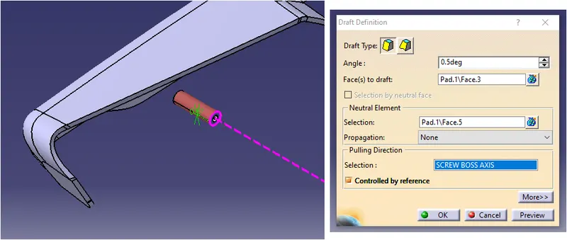
The draft angle should be given 0.5 degrees. we applying neutral elements and pulling direction also.
FLANGE OF ARMREST 2:
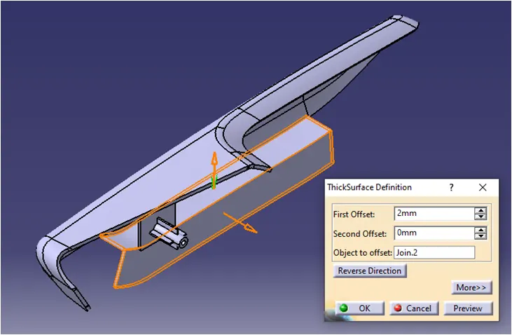
The thickness is 2mm of the first offset in the surface. We need to know about the directions like a forward and reverse direction
DRAFT FOR THE FLANGE:
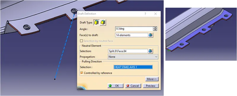
The draft angle should be given 0.5 degrees. we applying neutral elements and pulling direction also.
FILLETS IN FLANGE:
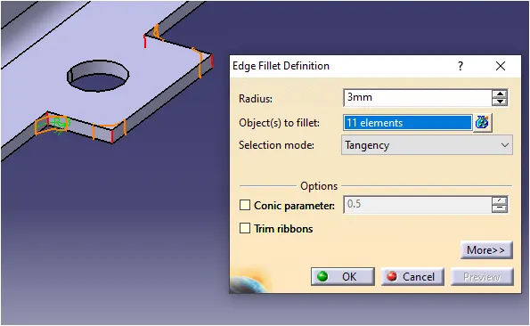
The fillet radius is 3mm is enough.
DRAFT ANALYSIS:
1.
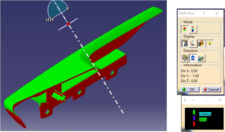
where is the green color showing in that place more than 0.49 degrees, where is the red color showing in that place below 0 degrees, and blue color showing places is 0 degrees.
2.
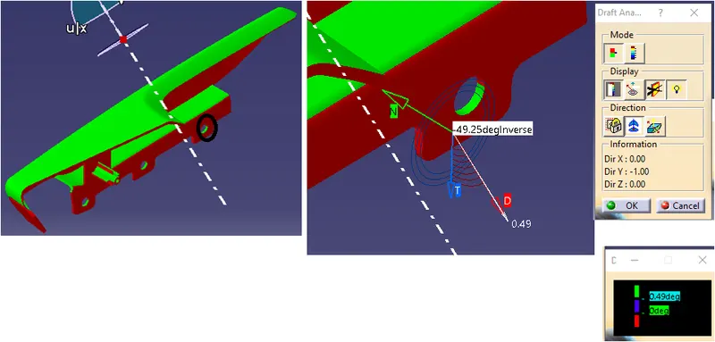
Here we saw in the measurement of angles variations. Which red surface is showing -49.25 deginverse, actually I already mention that is which surfaces are having red color in that particular surfaces having below 0 degrees.
3.
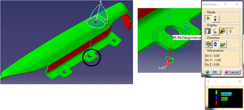
The circle is showing the analysis area The value is 89.962deg inverse. It means that the surface having more than 0.49 degrees that’s why it's showing green surface color.
4.
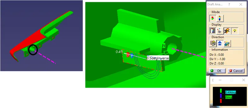
The circle is showing the analysis area The value is 89.962deg inverse. It means that the surface having more than 0.49 degrees that’s why it's showing green surface color.
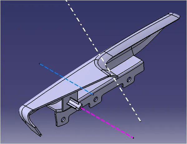
SOLID PART FOR ARM REST 2:
2.MAP POCKET:
CLASS A SURFACE:
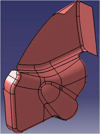
This class is given by the styling surface team. we need to create a class B surface by using a class-A surface. Next slide further we discussed in detail.
CLASS B SURFACE:
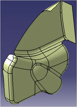
This is a class B surface. This surface is offset for a 2.5mm distance. ensure that we need only outside boundaries in that class b surface.
CLASS C SURFACE:
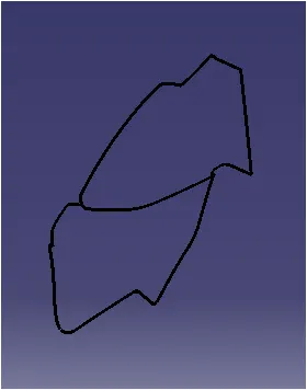
In this class C surface created by using the class-A surface. actually, we sweep at A surface outside the boundaries. Along with tooling direction and guide curves.
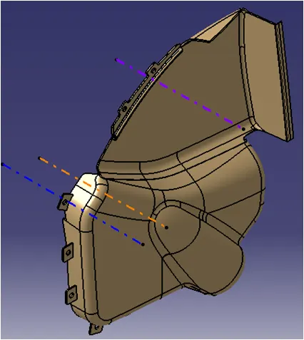
CLOSED VOLUME FOR MAP POCKET:
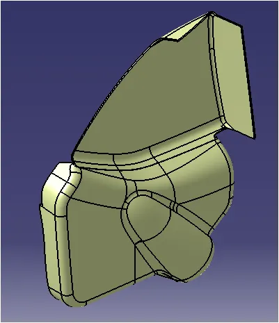
This is closed volume by using class A, class B, and class C surfaces.
FLANGE:
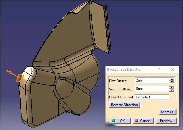
In MAP POCKET that flange thickness is 2mm. Once it's done after we go with union trim, in this case, what are all need or don’t need we selected on that union trim operation.
FLANGE CLEARANCE:
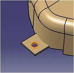
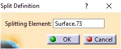
The clearance value is 0.1mm is enough for the flange. After that, the heat stake should come in the middle of the flange. The split direction should be outside direction.
DRAFT FOR FLANGE:
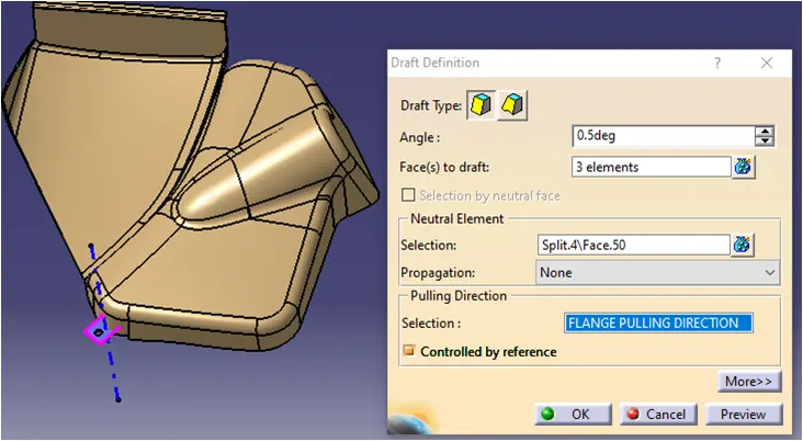
The draft angle should be given 0.5 degrees. we applying neutral elements and pulling direction also.
FILLET FOR FLANGE:
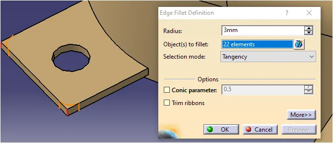
The fillet radius is 3mm is enough.
DRAFT ANALYSIS:
1.
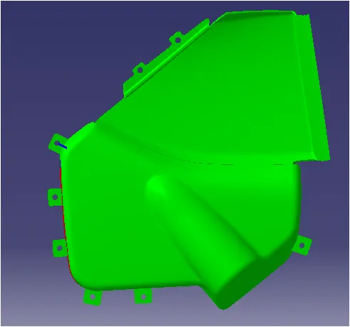
where is the green color showing in that place more than 0.49 degrees, where is the red color showing in that place below 0 degrees, and blue color showing places is 0 degrees.
2.
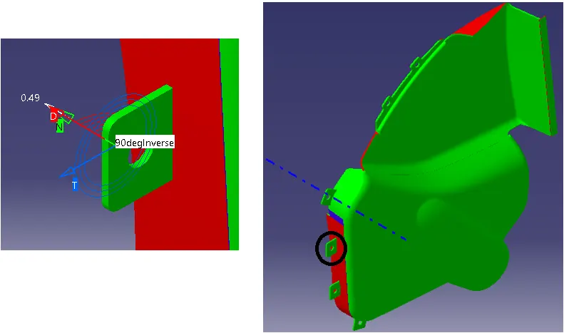
The circle is showing the analysis area The value is 90 deg inverse. It means that the surface having more than 0.49 degrees that’s why it's showing green surface color.
3.
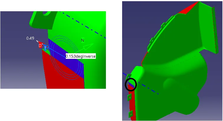
The circle is showing the analysis area The value is 0.153 deg inverse. It means that the surface having between 0-0.49 degrees that’s why it's showing blue surface color.
4.
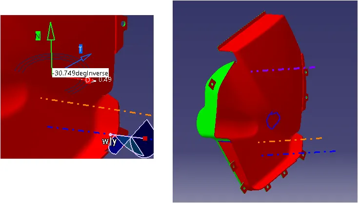
Here we saw in the measurement of angles variations. Which red surface is showing -30.749 degree inverse, actually I already I mention that is which surfaces are having red color in that particular surfaces having below 0 degrees.
CLOSED BODY FOR MAP POCKET:
3. LOWER SUBSTRATE:
CLASS A SURFACE:
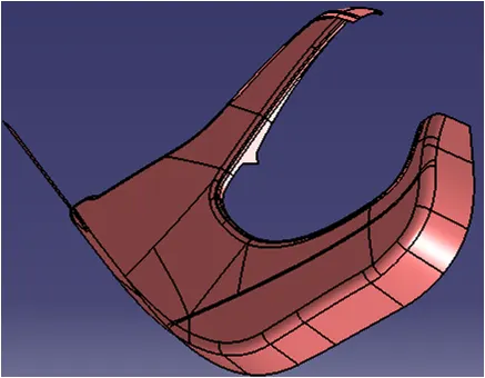
This class is given by the styling surface team. we need to create a class B surface by using a class-A surface. Next slide further we discussed in detail.
CLASS B SURFACE:
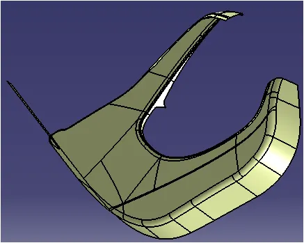
This is a class B surface. This surface is offset for a 2.5mm distance. ensure that we need only outside boundaries in that class b surface.
CLASS C SURFACE:
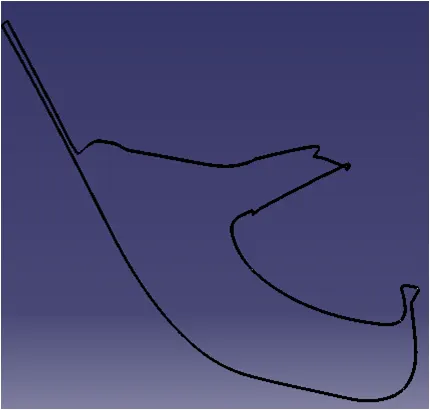
In this class C surface created by using the class-A surface. actually, we sweep at A surface outside the boundaries. Along with tooling direction and guide curves.
CLOSED VOLUME FOR LOWER SUBSTRATE:
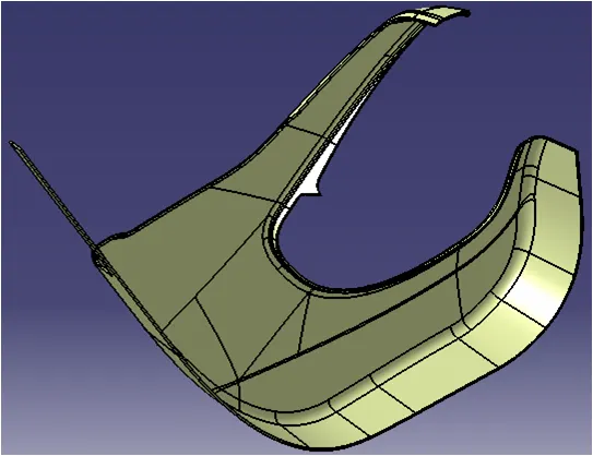
This is closed volume by using class A, class B, and class C surfaces.
CLOSED SURFACE THICKNESS:
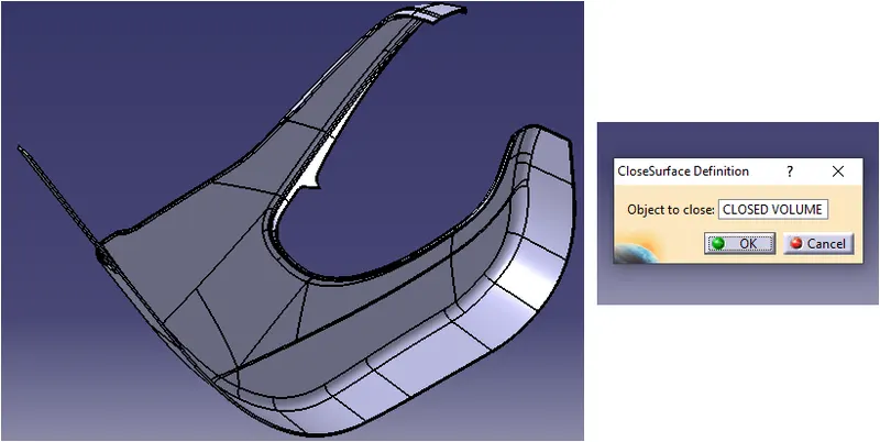
The closed volume should be a no-gap or no boundaries. After that easily we get solid the part.
HEAT STAKE THICKNESS:
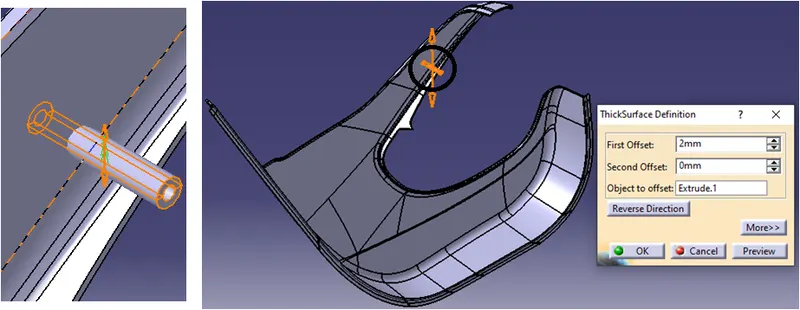
The heat stakes thickness is 2mm. Heat stake purpose is attached the two parts.
HEAT STAKE DRAFTED:
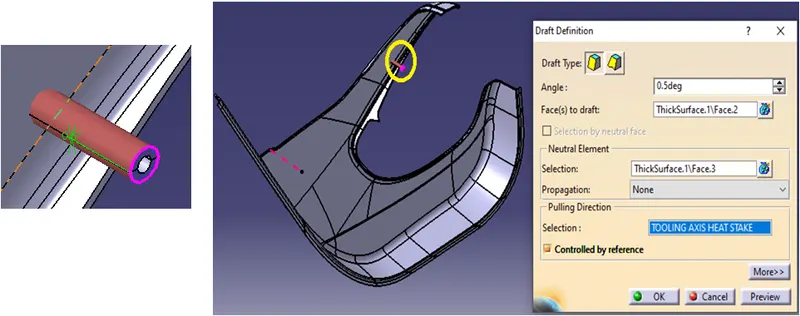
The draft angle should be given 0.5 degrees. we applying neutral elements and pulling direction also.
RIBS WITH HEAT STAKE:
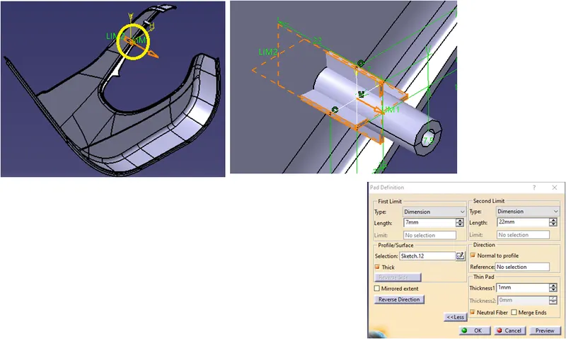
The ribs are supported to the lower substrate. The heat stake is within 25mm, we use ribs. If heat stake goes to more than 35+ we applying dog house for supporting.
RIBS DRAFTED:
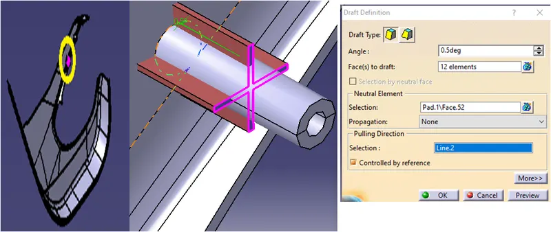
The draft angle should be given 0.5 degrees. we applying neutral elements and pulling direction also.
DOG HOUSE IN LOWER SUBSTRATE:
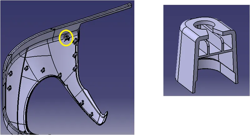
This dog house dimensions are standard, so we know that.
DOG HOUSE WITH PUSHPIN:
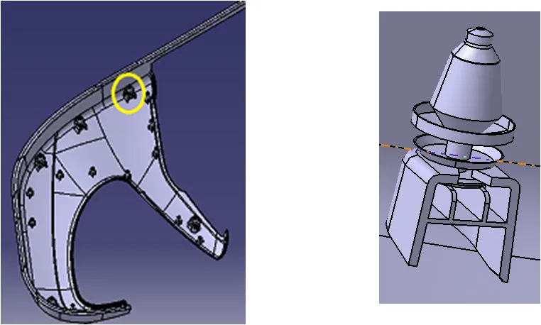
DRAFT ANALYSIS:
1.
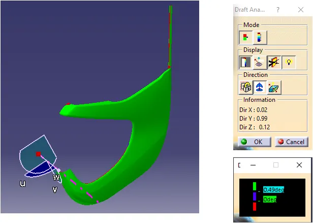
where is the green color showing in that place more than 0.49 degrees, where is the red color showing in that place below 0 degrees, and blue color showing places is 0 degrees.
2.
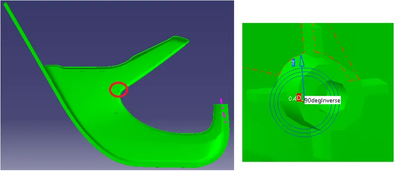
The circle is showing the analysis area The value is 90 deg inverse. It means that the surface having more than 0.49 degrees that’s why it's showing green surface color.
3.
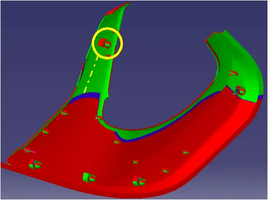
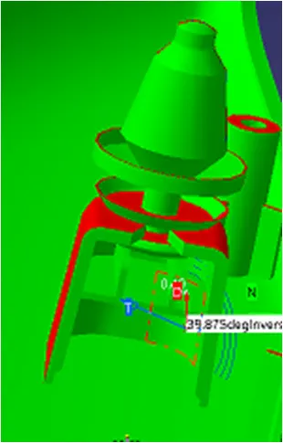
The circle is showing the analysis area The value is 39.875deg inverse. It means that the surface having more than 0.49 degrees that’s why it's showing green surface color.
4.
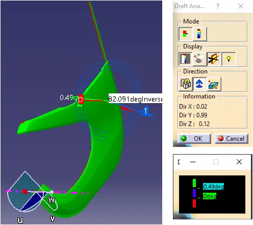
The circle is showing the analysis area The value is 82.091deg inverse. It means that the surface having more than 0.49 degrees that’s why it's showing green surface color.
SOLID PART FOR LOWER SUBSTRATE:
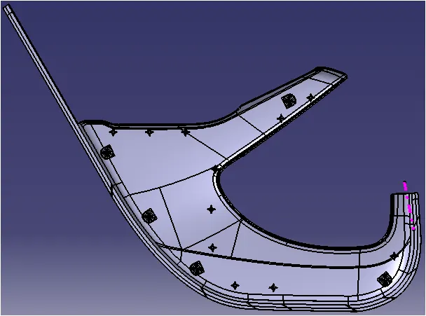
ASSEMBLY PRODUCT:
isometric view
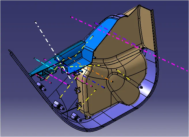
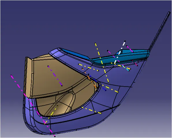
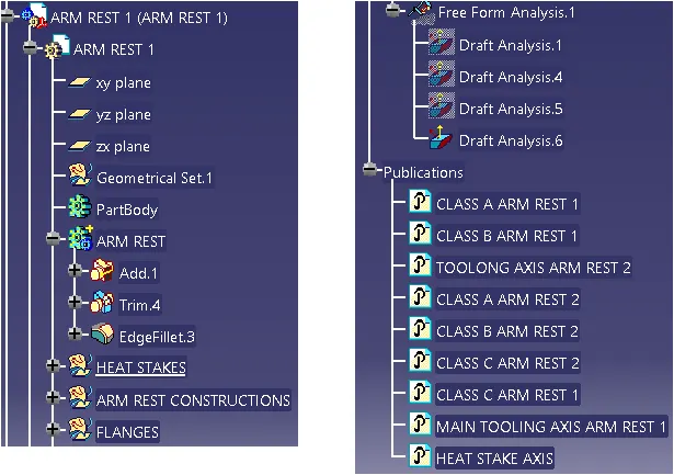
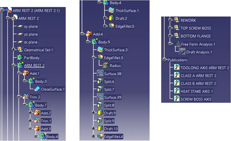
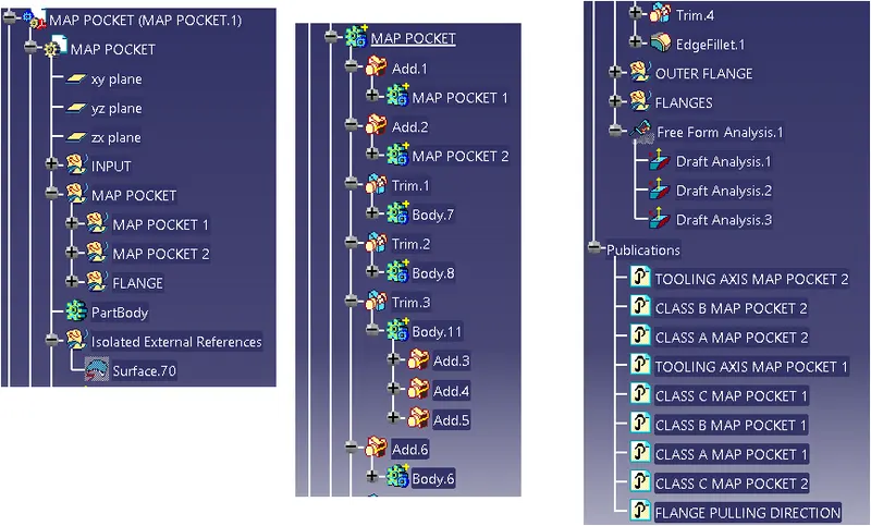
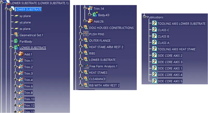
TREE STRUCTURES:
ARMREST 1:
ARMREST 2:
MAP POCKET:
LOWER SUBSTRATE:
RESULT:
I OBTAINED THE RESULTS BY USING THE ABOVE GIVEN INPUTS.
- Create thickened part using master section for reference
- Create the mounting features as per design guidelines in the industry and with master sections
- Apply material details :
- Draft analysis & Tooling analysis
- Creation of parting lines and check tooling feasibility
HENCE IT IS PROVED.