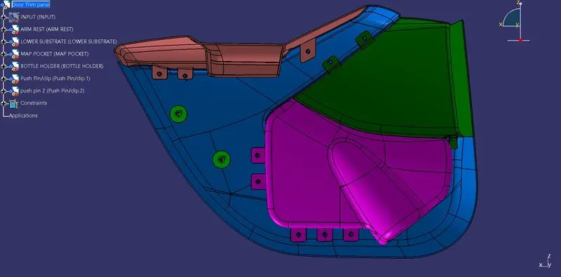
Week 11 - Final project
AIM
To create a door interior part from the inputs of class A surface along with the master section by following the design rules.
OBJECTIVES
- Create a sketch by using a Positioned sketch
- All the should be sketches should be Iso-Constrained
- Ensured Proper Tree Structure
- Create thickened part using master section for reference
- Create the mounting features as per design guidelines.
- Create Draft analysis & Tooling analysis
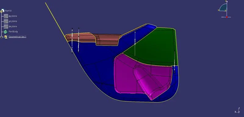
INPUT CLASS A SURFACE
PROCEDURE
- Check all the boundary whether it has connected or not.
- Check the model visually & choose the best tooling direction which should be easy for draft.
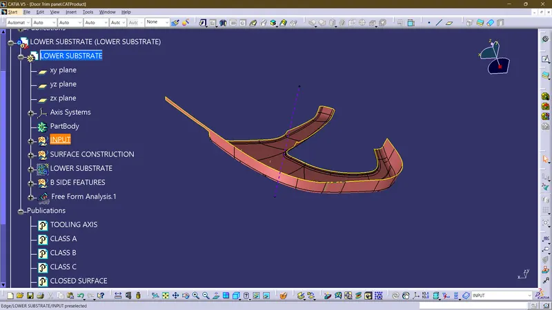
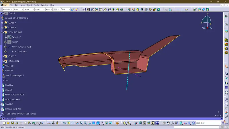
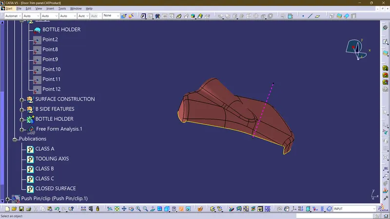
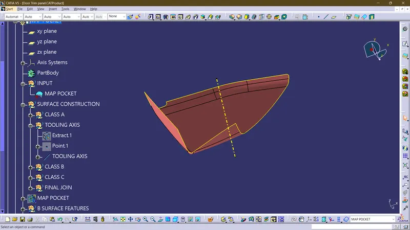
CREATING THE TOOLING AXIS
- create a point-direction line parallel to the y-axis and named as TOOLING AXIS
- create a side core axis or lifter axis where necessary
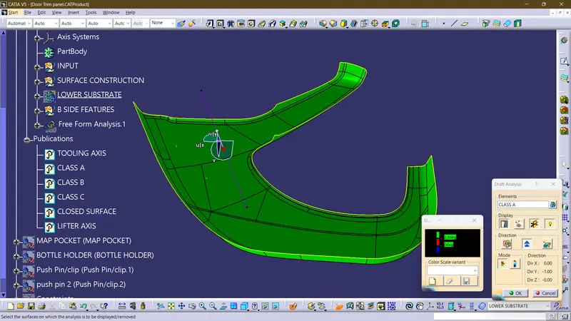
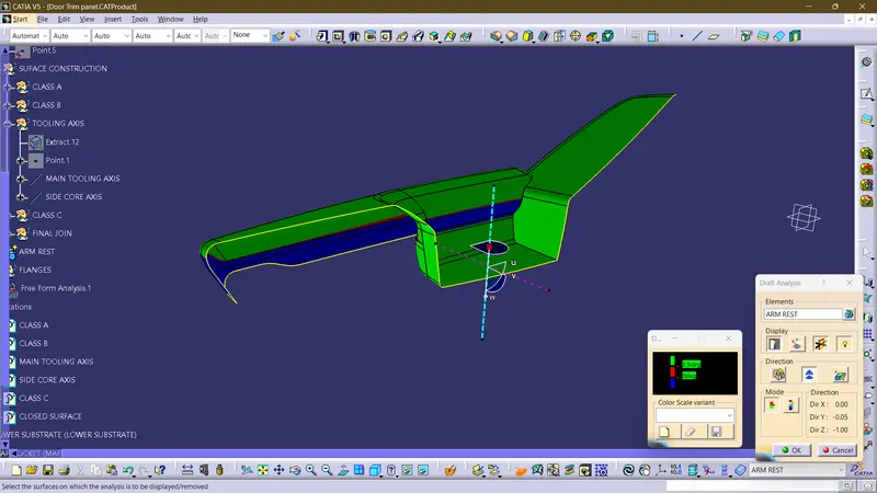
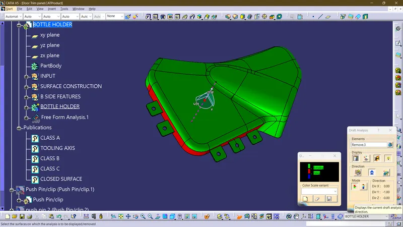
DRAFT ANALYSIS ON CLASS A
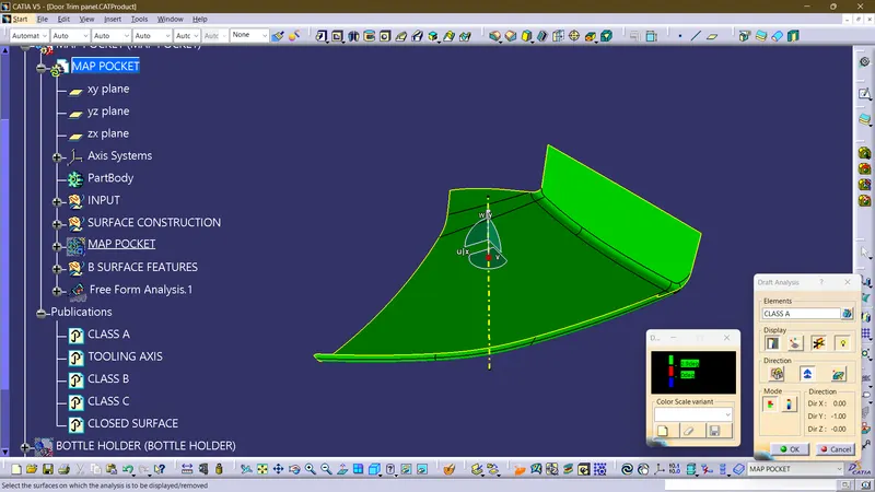
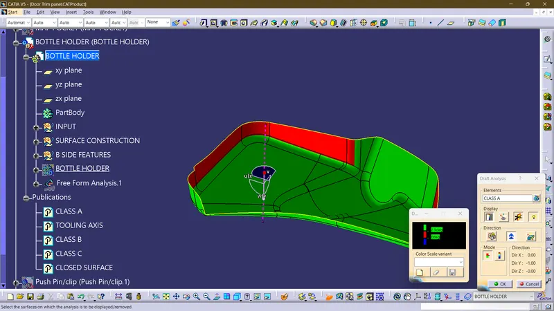
CREATION OF CLASS B SURFACE
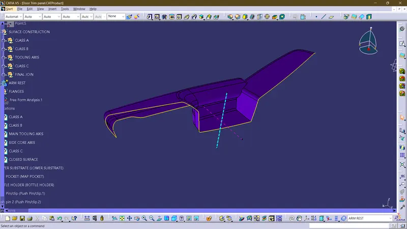
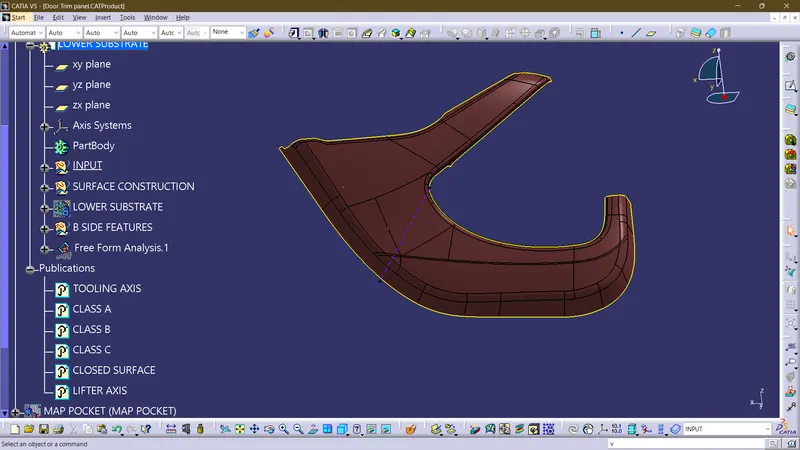
- Insert a new geometrical set. Measure the value of thickness in the master section.
- Offset the class A surface to 2.5mm.
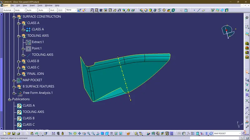
CREATION OF CLASS C SURFACE
- Analyze the class A once where the sweep is easier to create toward tooling direction
- Create a boundary using limitation points wherever possible for sweep
- Sweep the above boundaries for 3 degrees towards the tooling axis or 90 deg with surface reference.
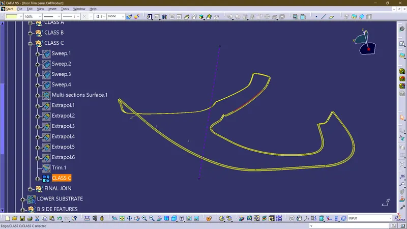
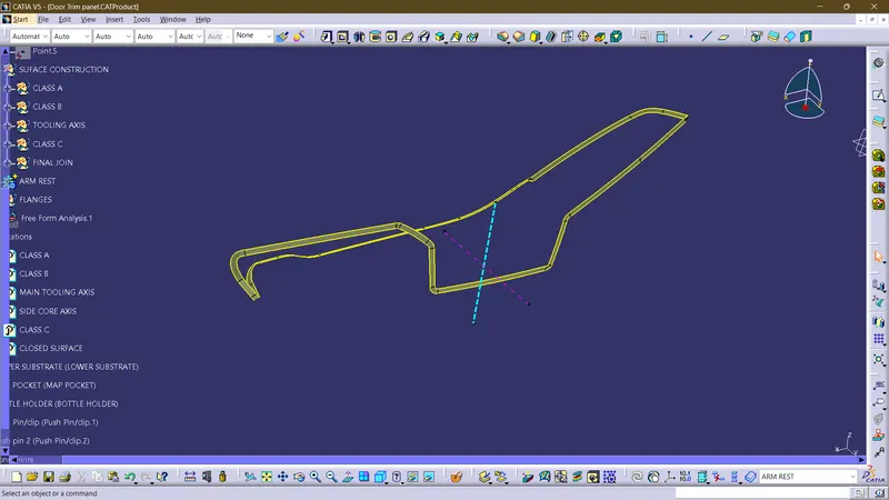
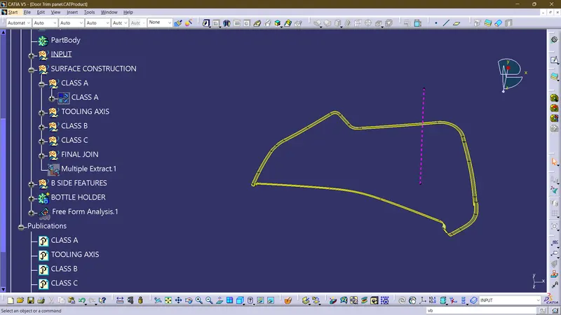
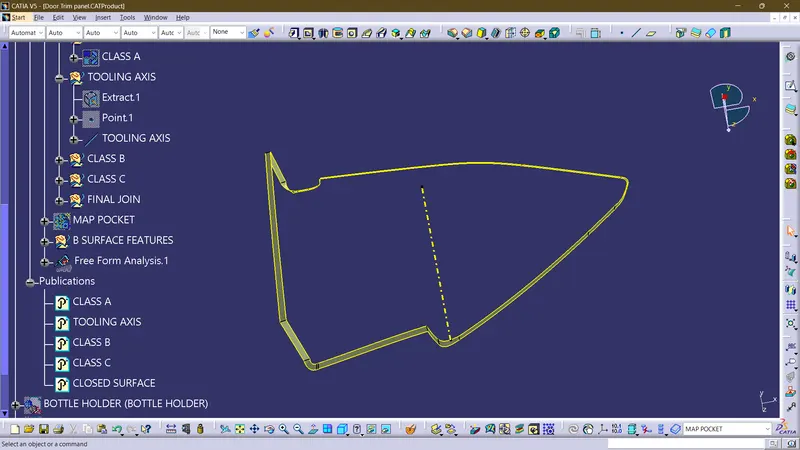
- Now join CLASS A and CLASS C, then trim it with CLASS B.
- Use close surface tool in part workbench to create a solid body out of the final close surface
CLOSED SOLID BODY
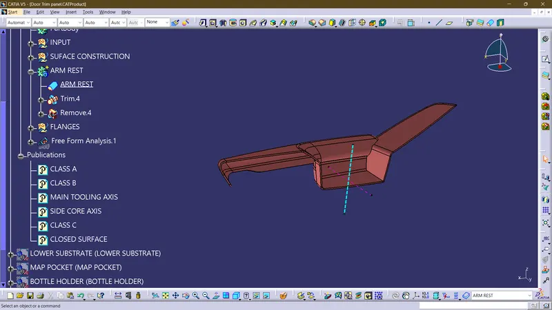
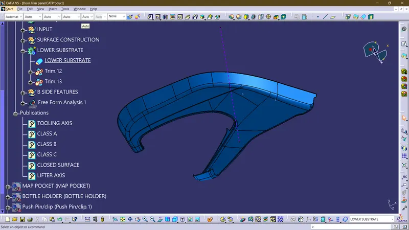
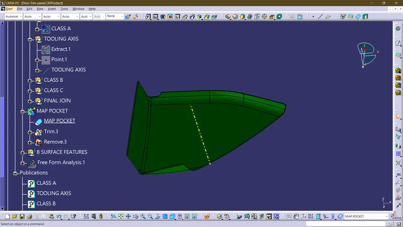
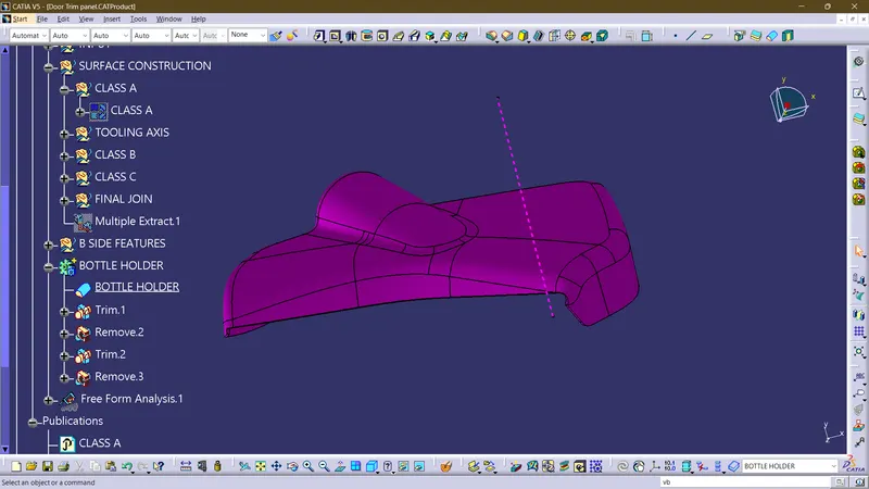
CREATION OF B-SIDE ATTACHMENT FEATURES
DOG HOUSE
Create a dog house by following design rules.
Dog house rule
- B=4mm
- t=2.5mm
- C=0.4 * t=1mm
- Draft to 5 degree
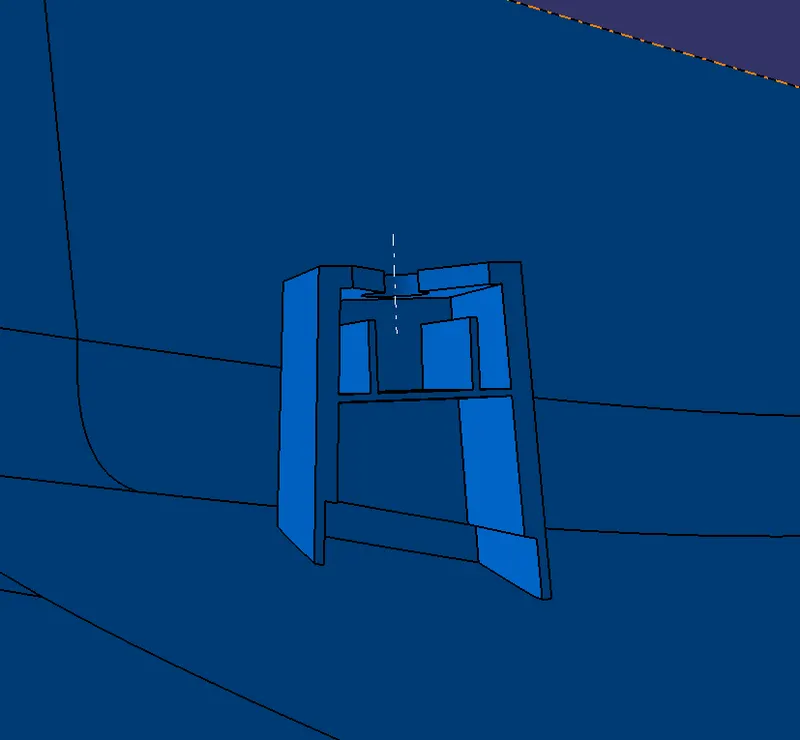
- Add push pin using assembly workbench tools.
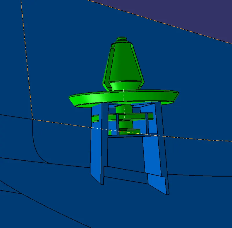
HEAT STAKES WITH LOCATORS
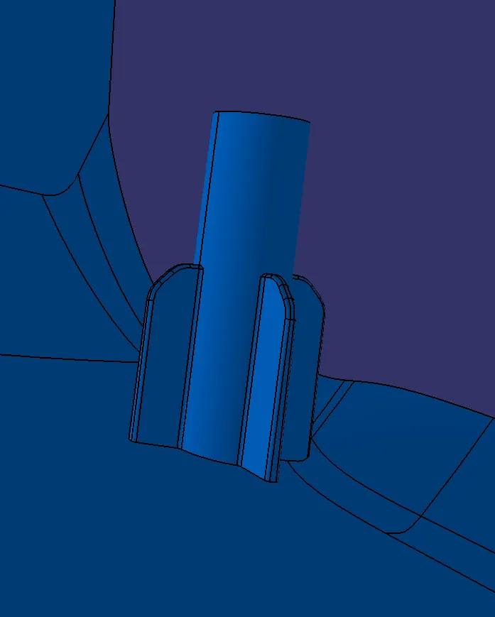
HEAT STAKES
- Extract the surface that we going to create a heat stake
- Use positioned sketch and draw a heat stakes sketch
- Use pad commands for the sketch to till we required
- Draft the stakes minimum of 0.5 degree
- Add fillet 0.5mm o all faces
- Assemble the heat stake to lower substrate solid
- Maintain a 50mm minimum between two heat stakes
- Translate the heats takes to wherever needed
- Trim all heat stakes with lower substrate solid
LOCATOR
- Extract the surface that we going to create locator
- Use positiioned sketch and draw a locator sketch
- Use pad commands for the sketch to till we required
- Draft the locator for minimum of 0.5 degree
- Add fillet 0.5mm o all faces
- Assemble the locator to lower subtrate solid
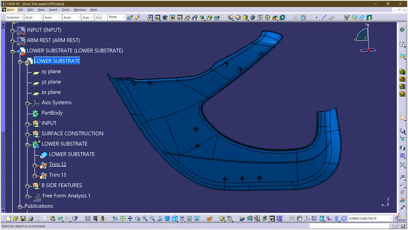
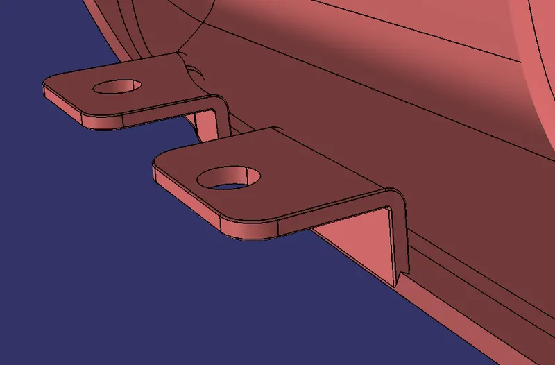
FLANGE
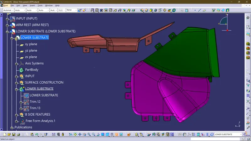
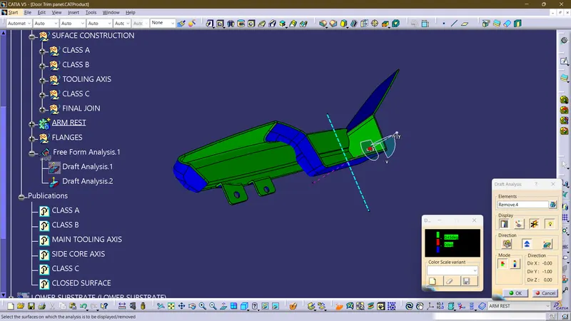
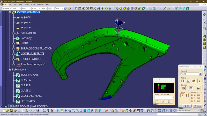
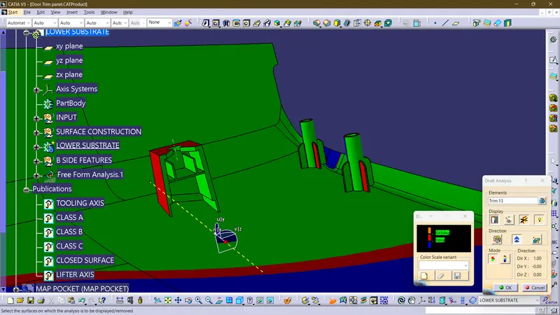
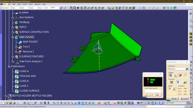
DRAFT ANALYSIS REPORT OF FINAL BODY WITH ATTACHMENT FEATURES
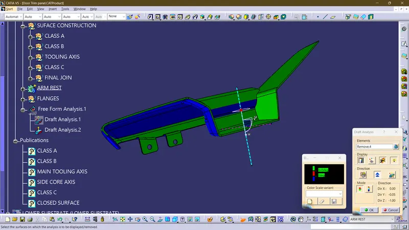
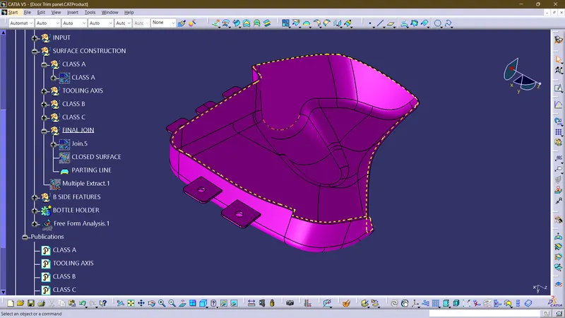
CREATION OF PARTING LINE
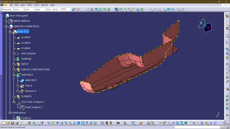
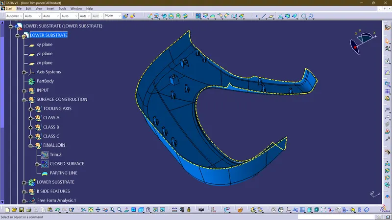
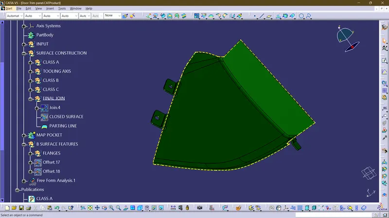
The parting line is used to the differentiate between core and cavity
'NOTE = THE PARTING LINE BELOW IS CREATED WITHOUT CONSIDERING THE ATTACHMENT FEATURES'
FINAL ASSEMBLY