Week 11 - Final project
Week 11 - Final project
AIM: Development of a Door Trim panel
Creation of CAD model considering following inputs as like in OEM and tier1 companies
- a) Class A surface
- b) Nominal thickness : Refer master sections
- c) Attachment strategy :
- Find a attachment strategy for the door panel complete work.
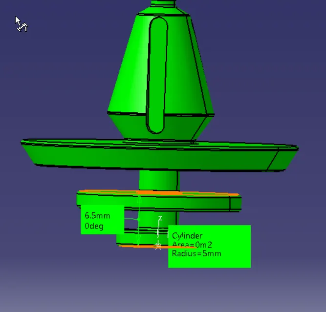
- Use Push pin with Dog house for Lower substrate – Door panel attachment
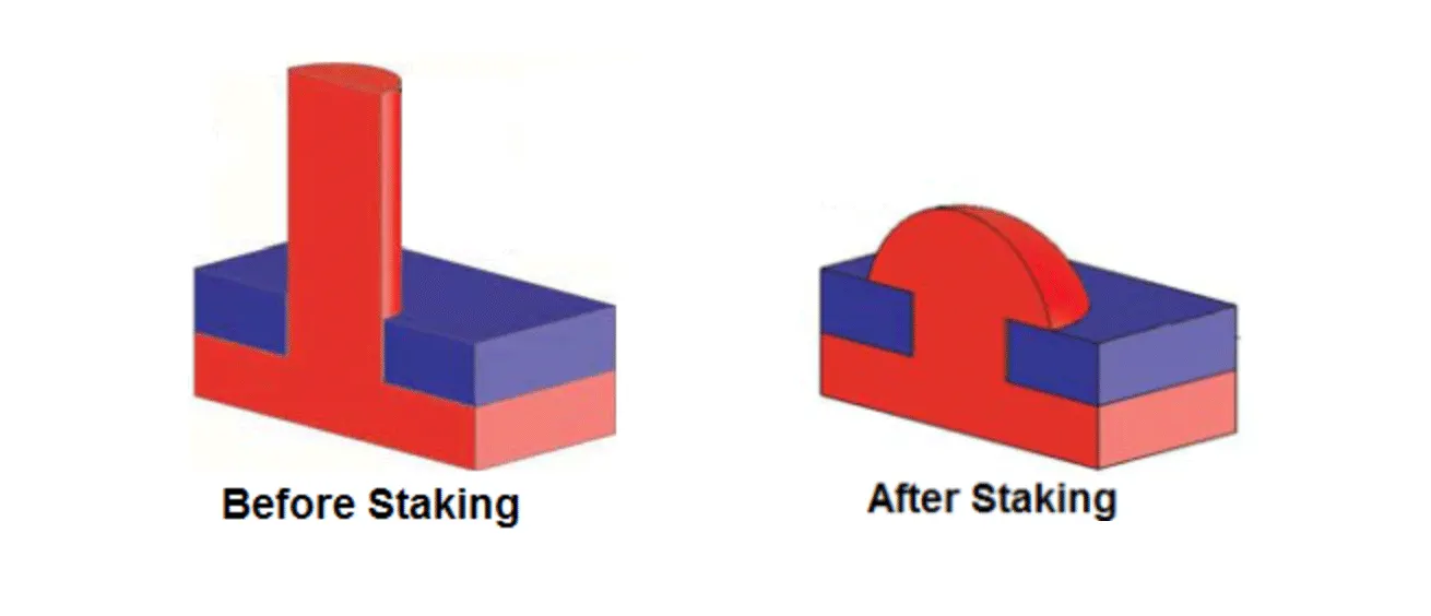
- Use heat stakes for part to part attachment
sol:
TERMINOLOGY:
CLASS A SURFACE: The Class A finish is the highest quality finish Microform Precision can provide. It is often specified for high visibility surfaces such as control panels, front covers, etc. in which the Customer demands the highest quality appearance.
CLASS B SURFACE:Class B surface is the surface that is offseted from class A and is not directly visible from outside, this is where all the engineering fetures such as doghouse ,screwhouse etc are added.
CLASS C SURFACE: surface that join classA and classC sufraces. it is developed with respect to tooling axis.
TOOLING AXIS: an axis that is developed so as to remove the the material from the mold without difficulty.
DRAFT ANGLE: minimumm anfle of 3 degee is provided to the class c surcace to remove the cast
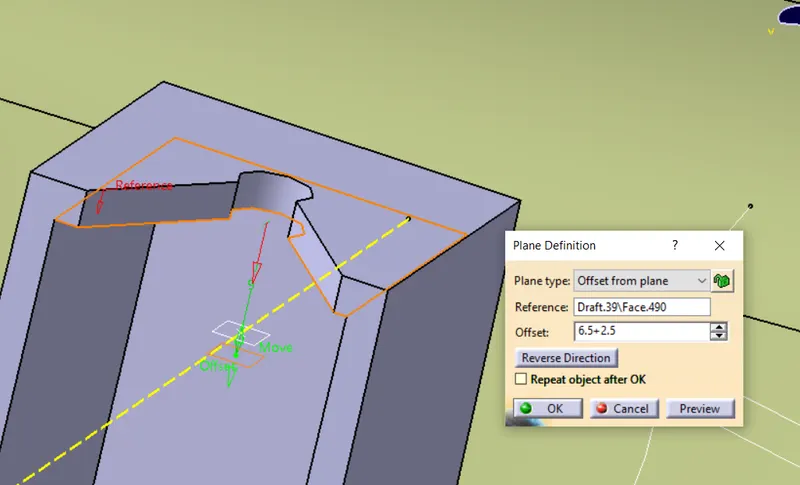
DOGHOUSE: engineering feture that is used to support features that require a raised position from main body.it mat support scruebose , heat stakes.
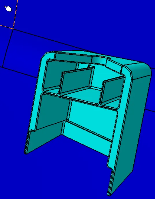
LOCATORS: These arenpetrutions that are used to place theparts to the correct location with ease,. it helps to lock the and keep only 1 degree of motion
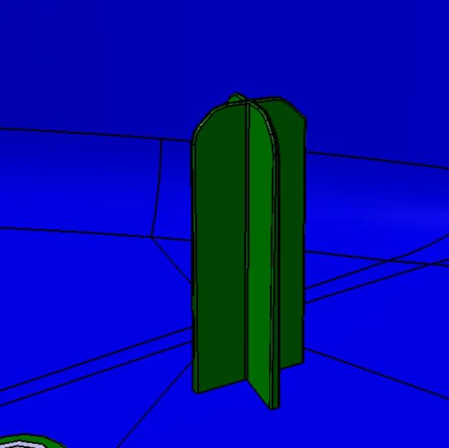
HEAT STAKES: These are petrutions made to as to plastic weld the parts with simple heat aplication.
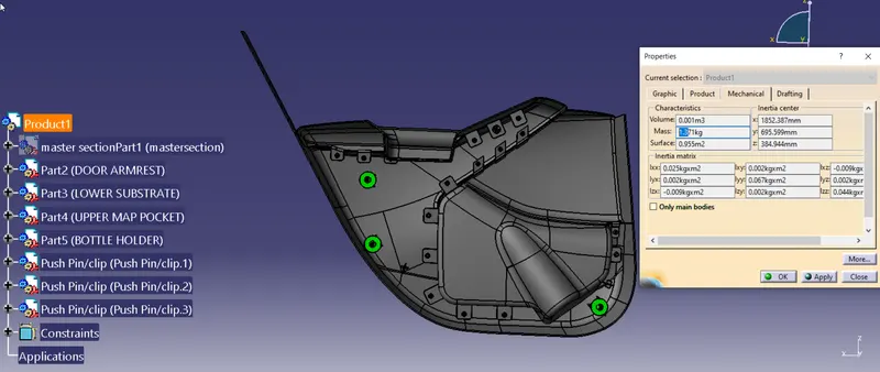
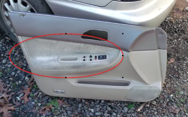
Below image shows a fully assambled doorpanel
Given A surface is projected to a assymbly product file, subparts are created and parts are imported to its spesific directory. as shown in figure below
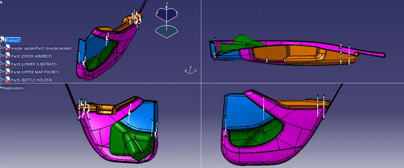
split the work to create a solid surface ogf each patrs
DOOR ARMREST
Asection of doortrim procided
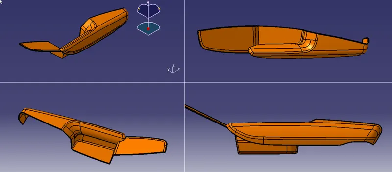
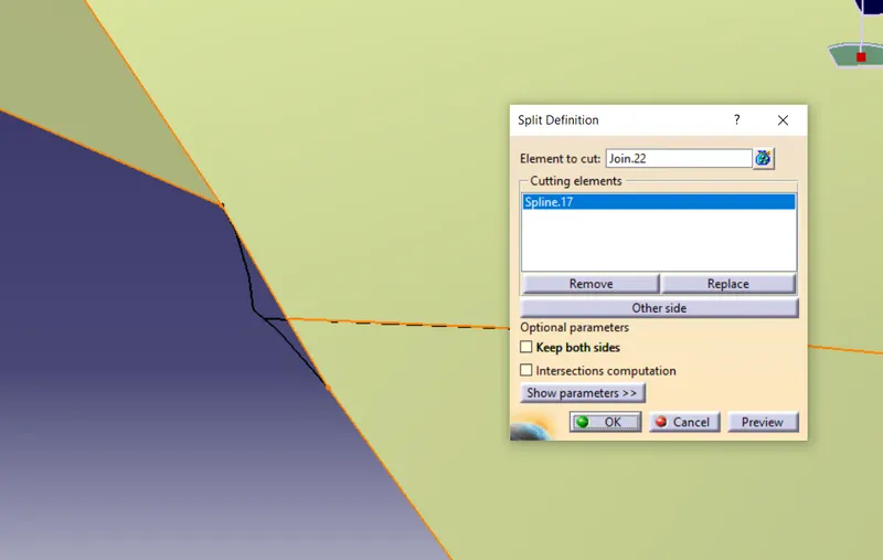
First check any abnormalities in boundry of provided A surface
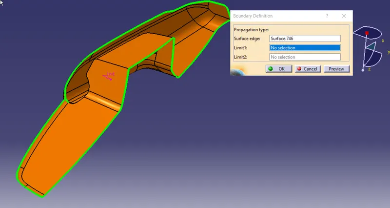
there seem to be a small gap forme. so correct it
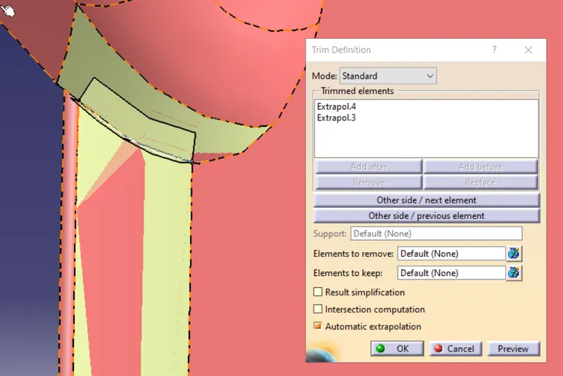
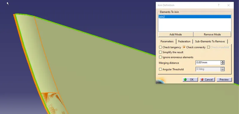
extract surface, create border and extrapolate, trim and join the surface
no disjoint surface to be found
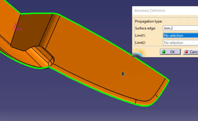
Also the small fillet to be removed as it is a joint for a diffrent part
Tooling axis:
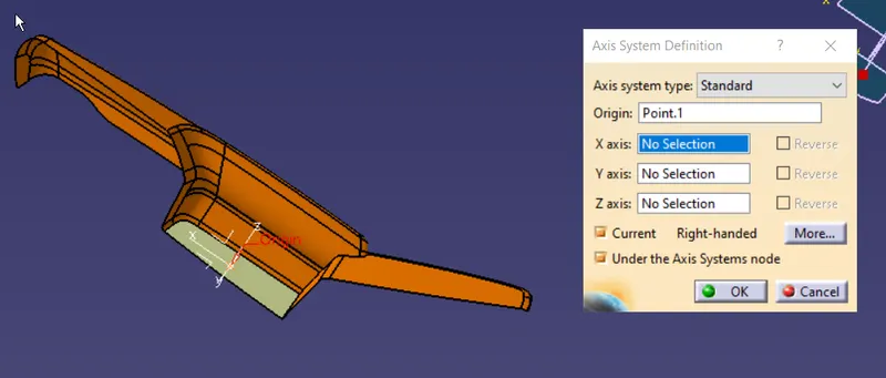
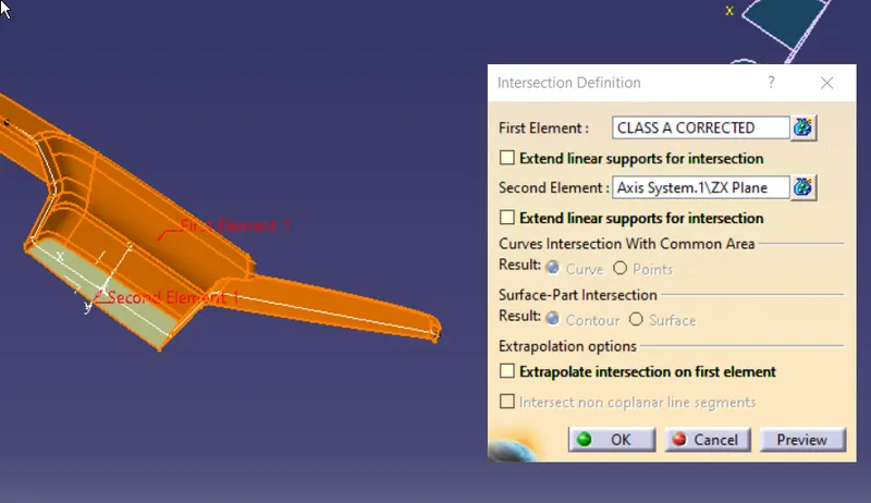
Main dummy1 tooling axis
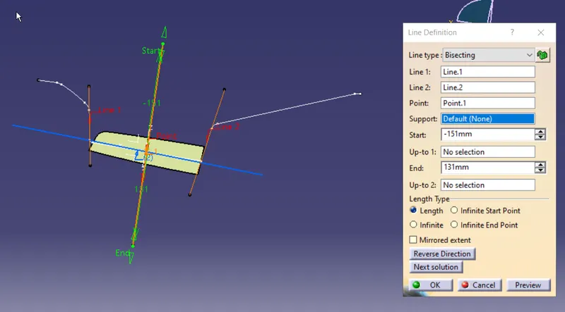
creat a catrition axis , use intersect planes,
extend the lines as shown
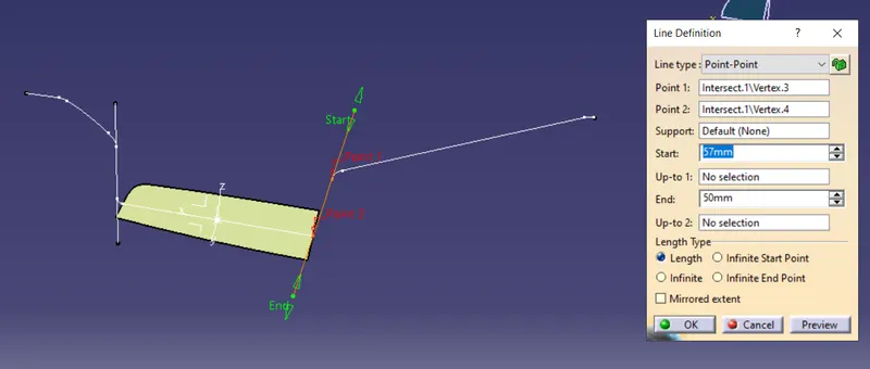
Create a bisecting line wrt the lines drawn and point formed this would be main dummy tooling axis 1
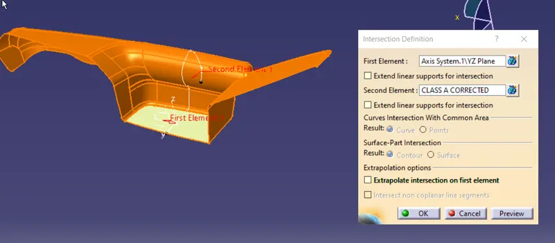
Create a second intersection with yz carition reference plane
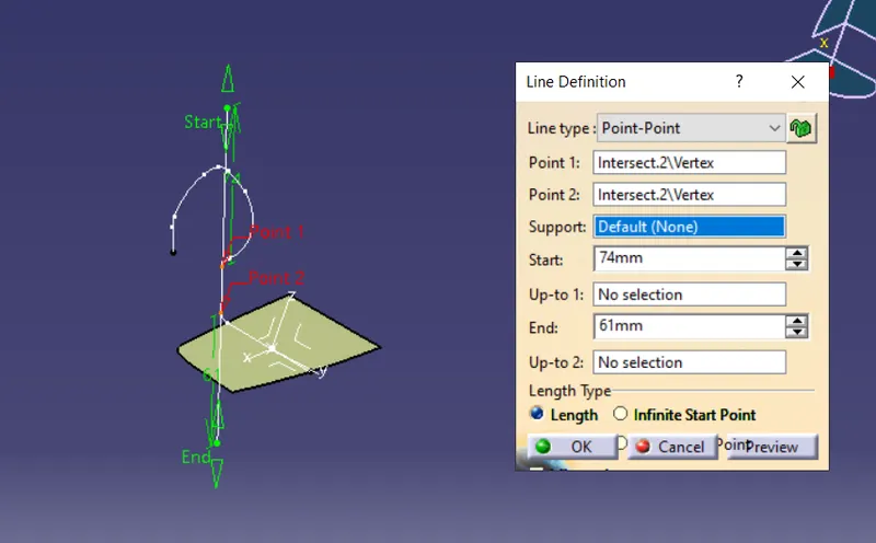
create a line normal to surface
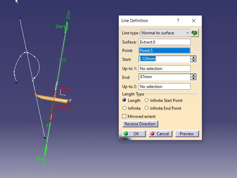
shift line by 5degree to give a safe draft angle
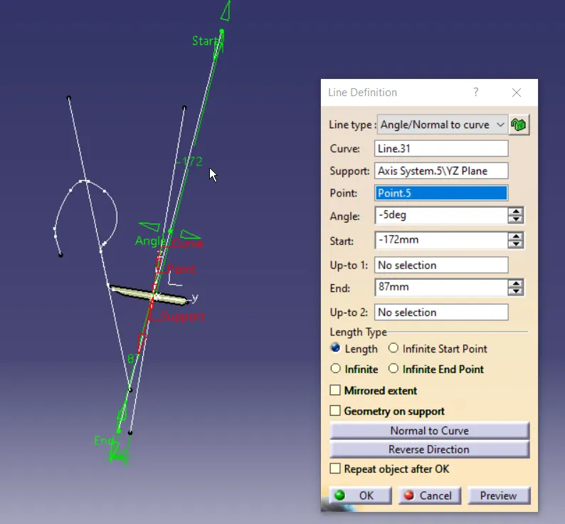
now bisect to get the 2 linES TO GET FINAL axis
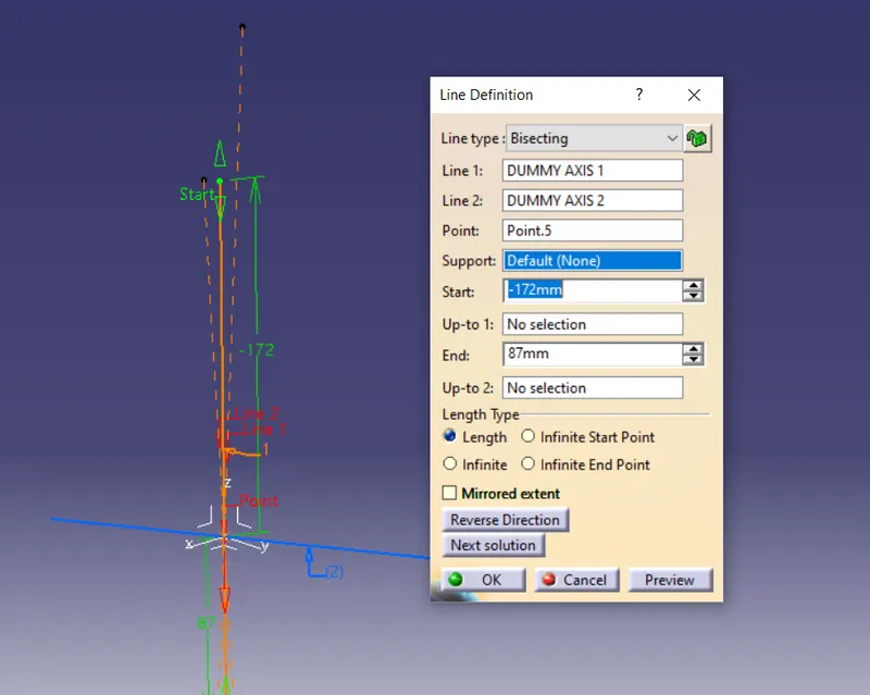
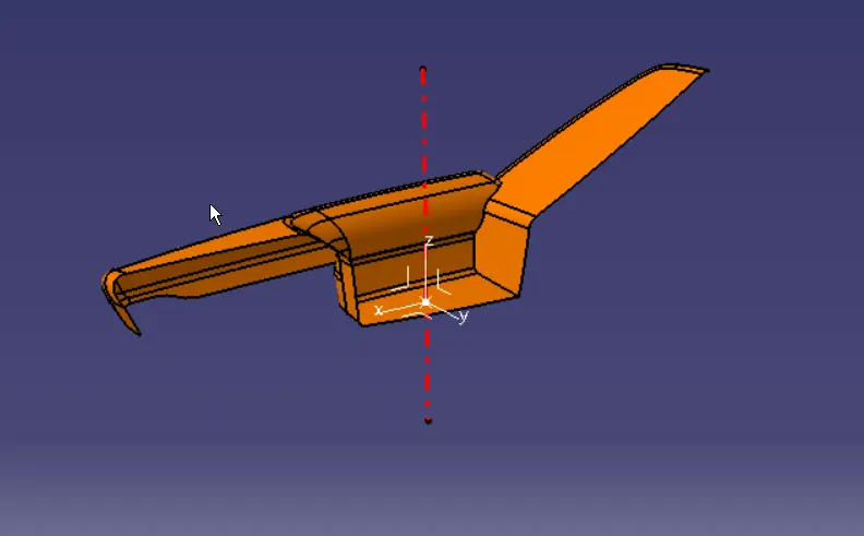
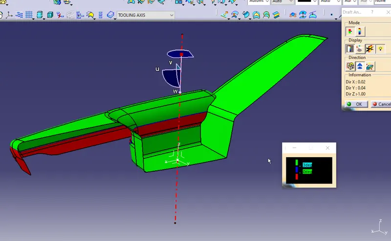
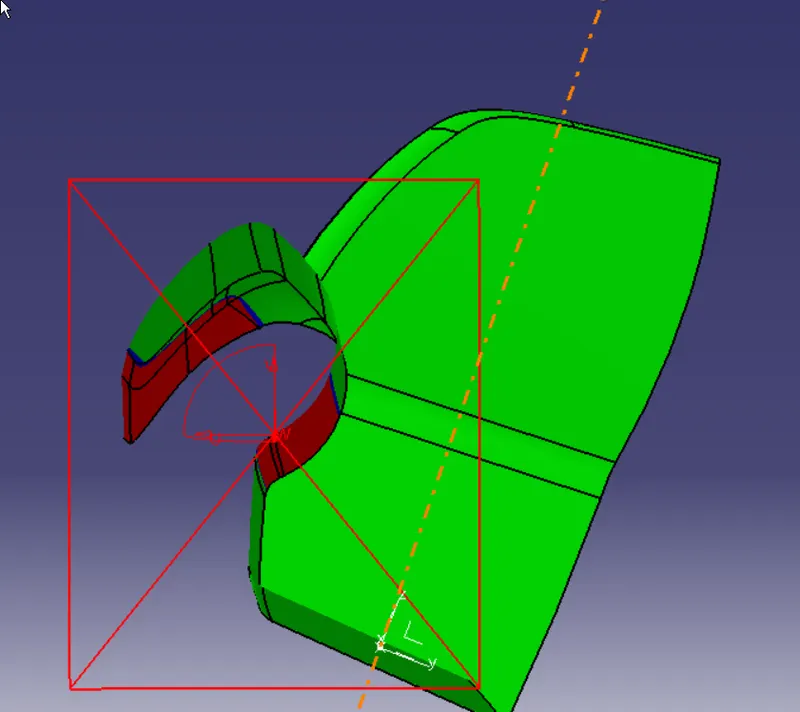
We can notice that the A section needs to be redesigned as the draft angle can not be satisfied.The design must be reverted to the Class A designer.or multiple tooling axismhas to be generated
lets add a tside tooling axis normal to tooling axis in y axis
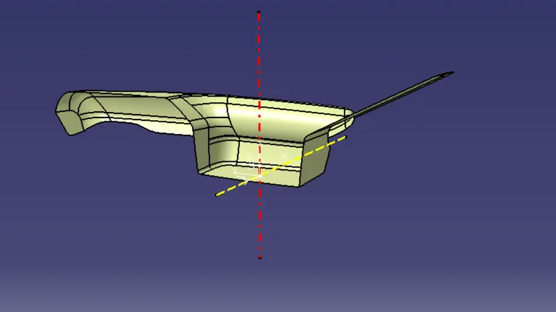
Lets assume it is a gree signal for this component.
CREATION OF CLASS B SURFACE:
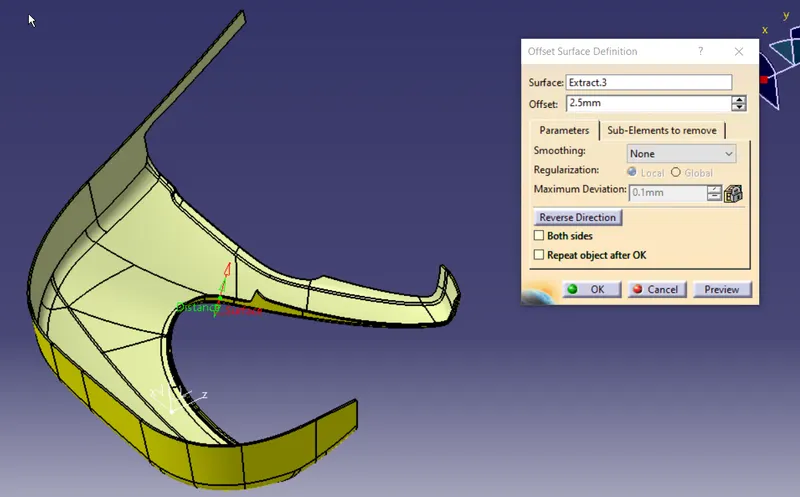
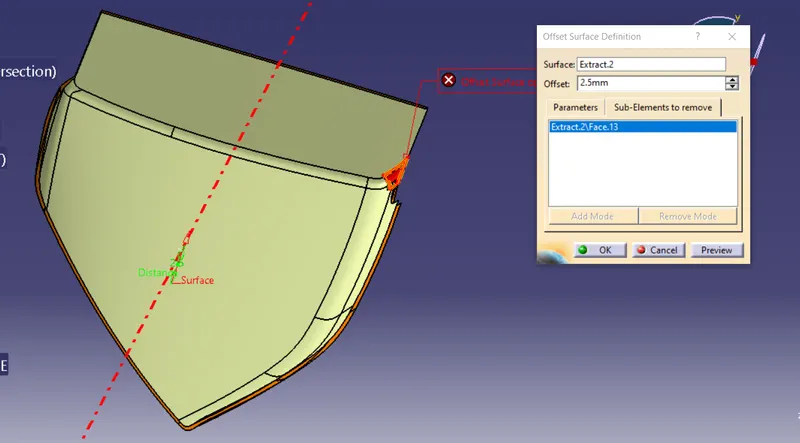
Extract the A surface and ofset it by 2.5mm
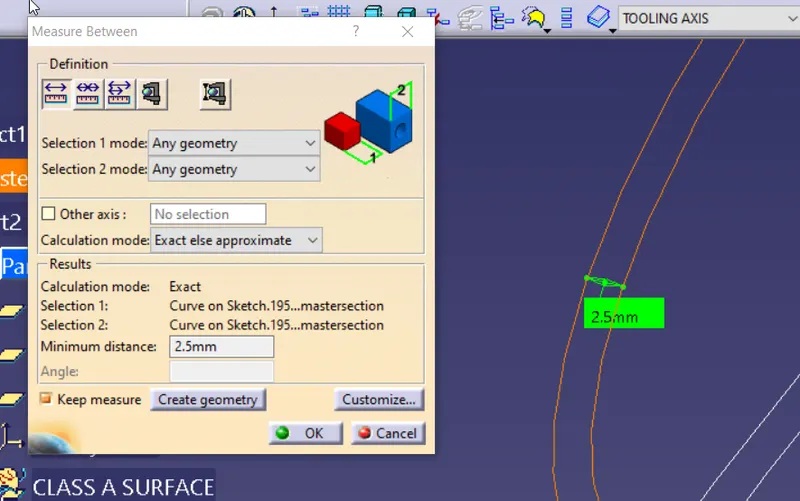
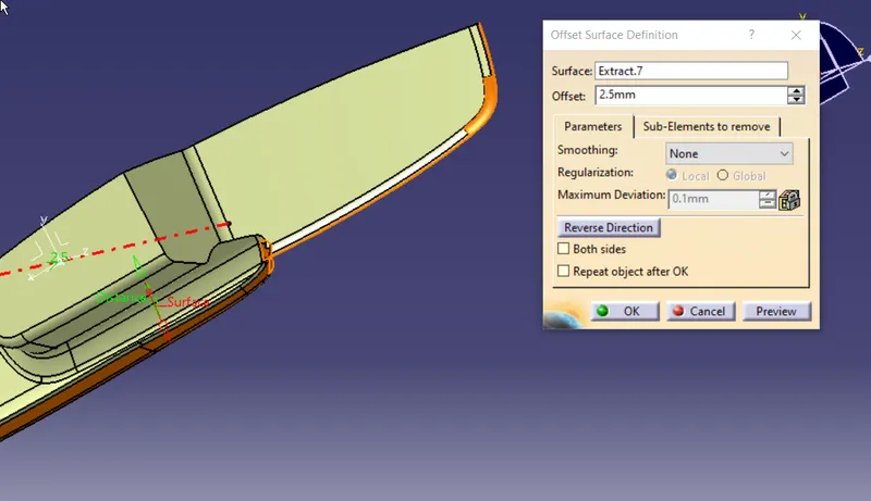
few surface faild to off set . so manully create the missing surface
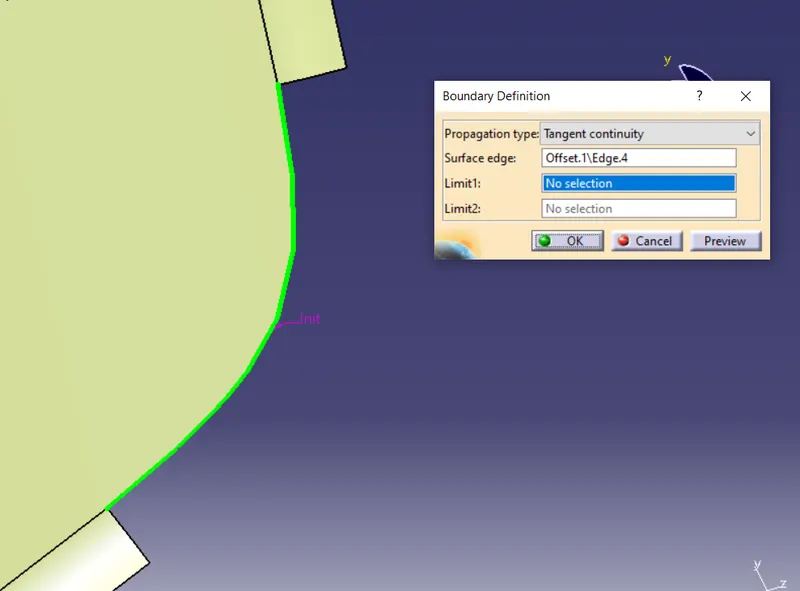
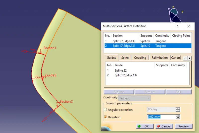
join the patch surface , and check for discontinued surface
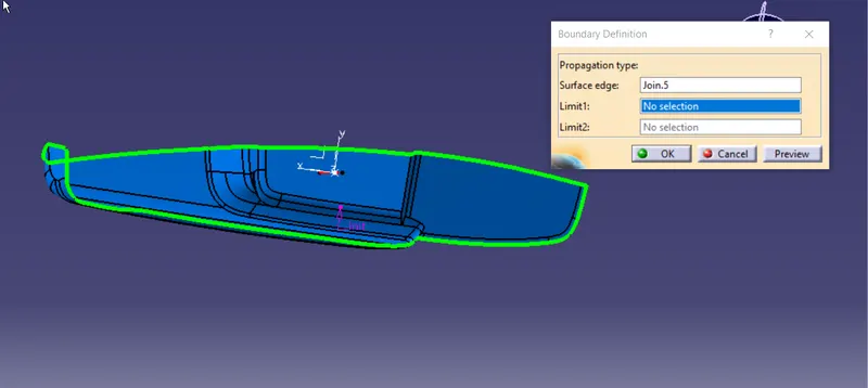
Creation of class C surface with respect to tooling axis
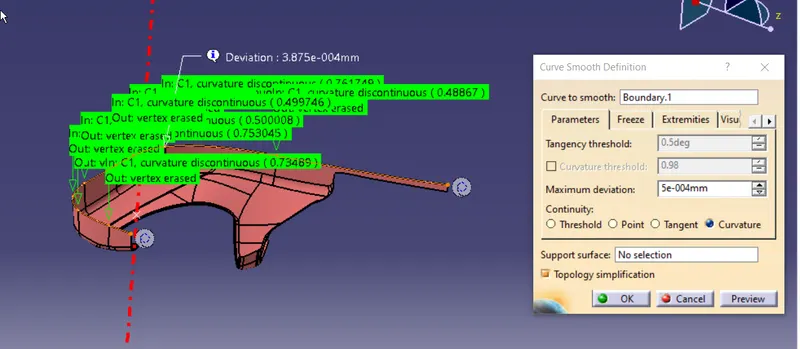
Create boundry , moothen if nessorry
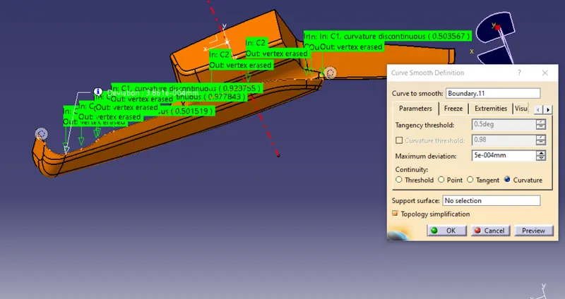
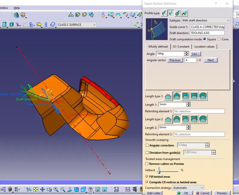
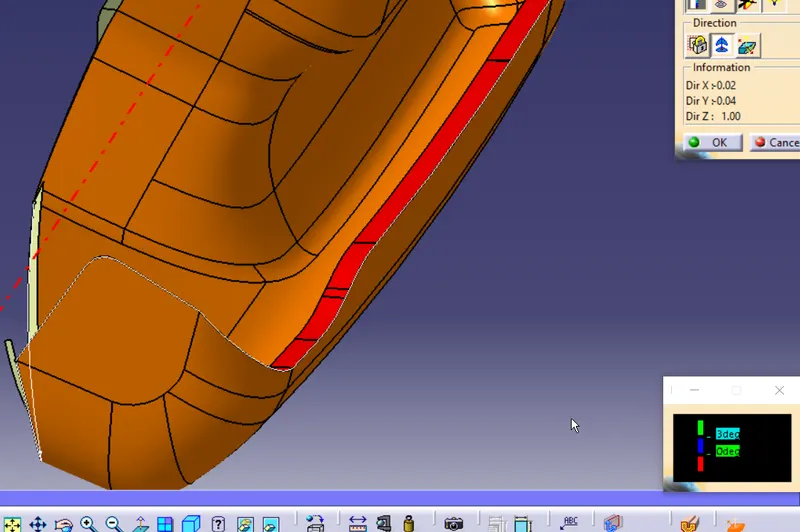
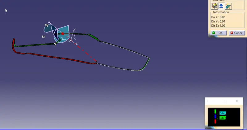
the surface that are parallal or near parallel to tooling axis do not requre a proper draft asit will change the sgape of final product
draft analysis of class c
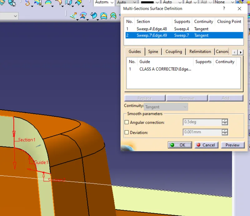
extrapolate the areas where C and B do not meet
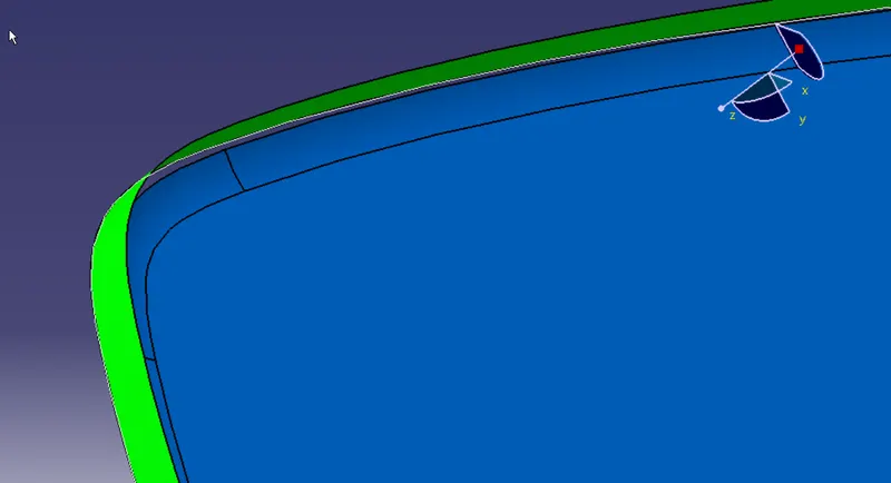
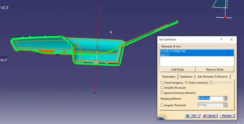
combine classA and class C
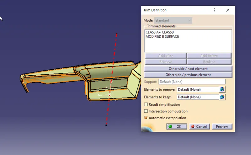
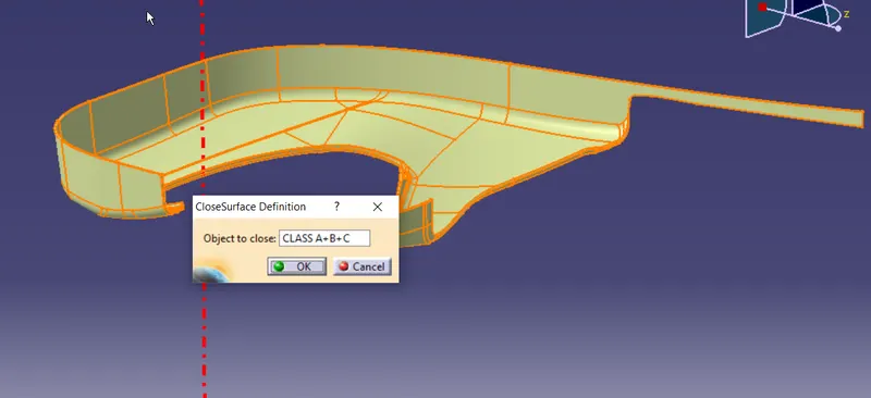
Trimm class A+C with extrapolated B surface to get closed body
Check for boundy condition
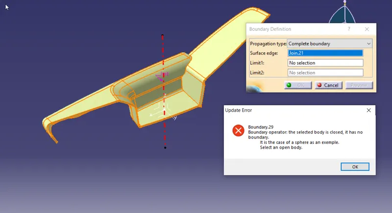
C concert to solid
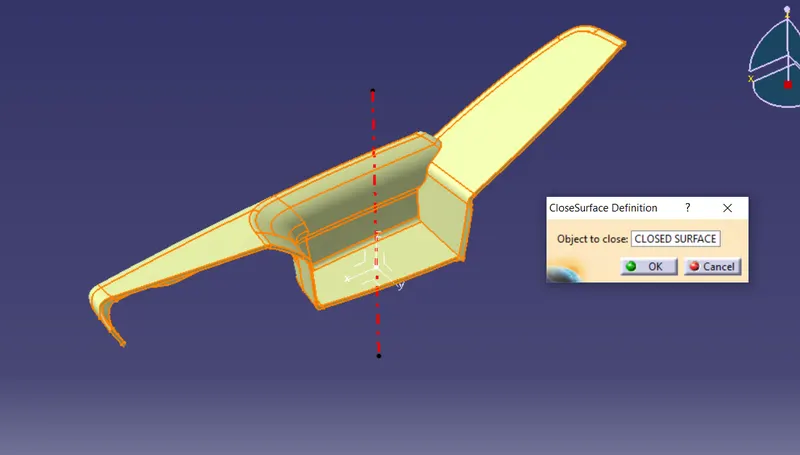
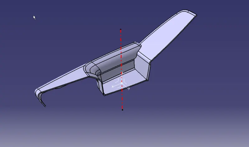
PART2: LOWER SUBSTRATE
Given A surface
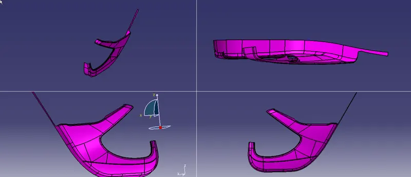
check for any deformityor patchs
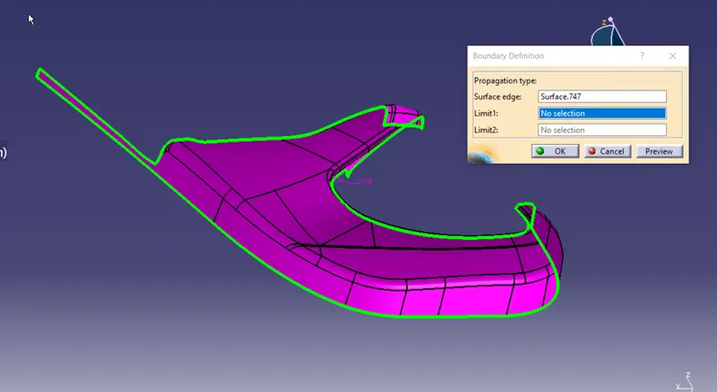
no patches found , so next find tooling axis.
Creation of TOOLING AXIS
Extract a surface find midpoint, add carition axis.
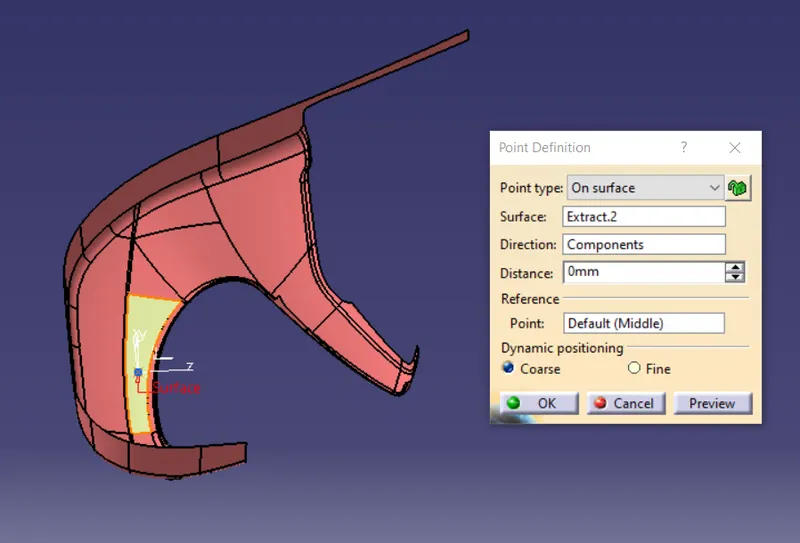
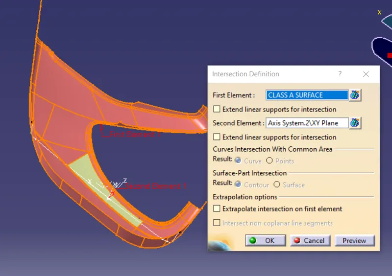
Intersection with respect to XY plane
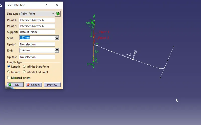
extend extereme lines
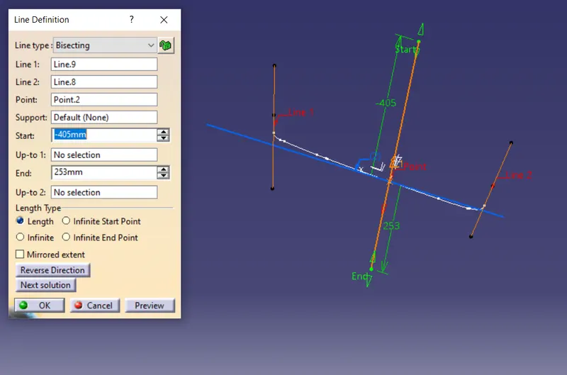
bisect lines to create DUMMY TOOLING AXIS1
Intersection with respect to YZ
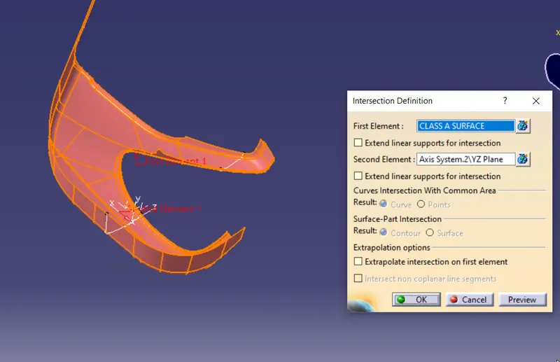
bisect to create DUMMY TOOLING AXIS 2
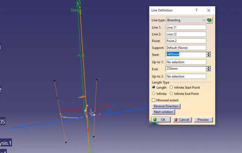
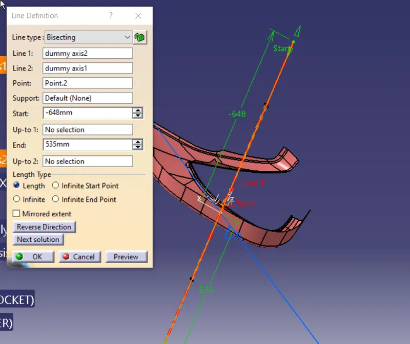
Now bisect dummy1 and dummy 2 to get main tooling axis
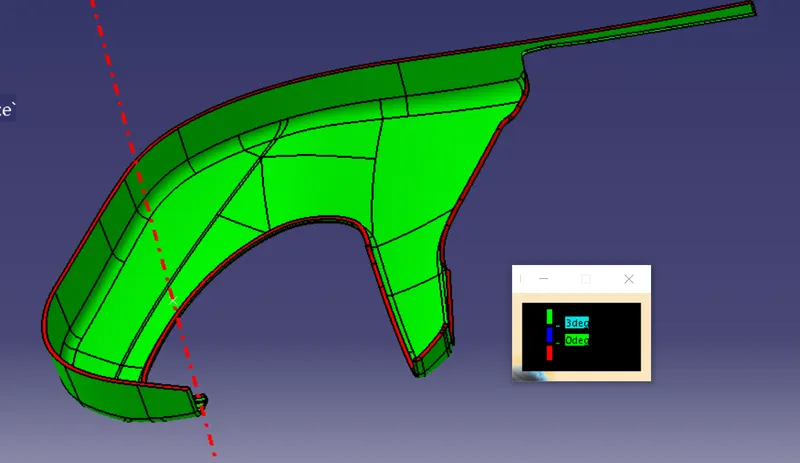
draft analysisi of classA
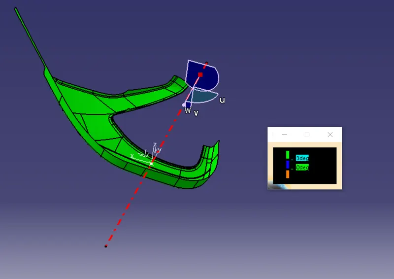
sussussfull draft.
Creation of B surface
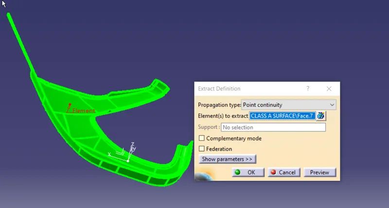
OFFSET EXTRACT BY 2.5MM
CREATE BOUNDRY ,SMOOTHN IF REQUIRED
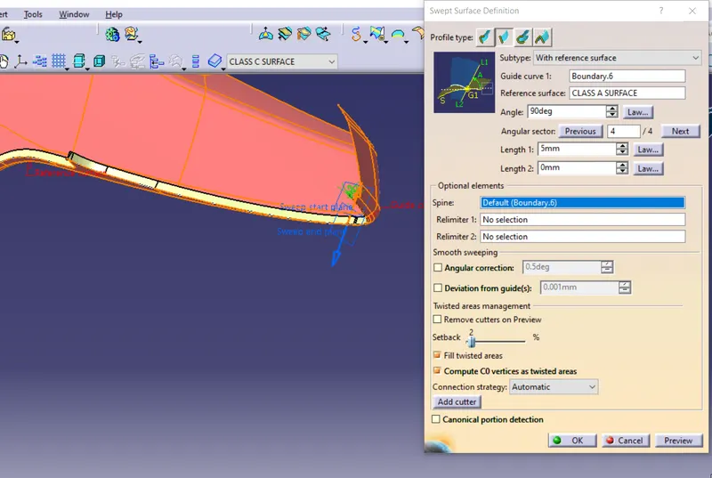
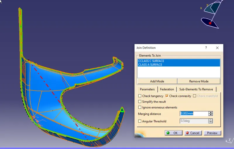
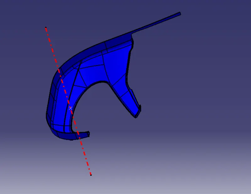
all surface joined ,Class C surface
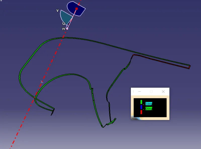
JOIN CLASS A + CLASS C
surface in rud are assume to be safe as those planes are normal to the tangent
CLASS A + CLASS B + CLASS C
extrapolate B surface if nessesory
trim the surface
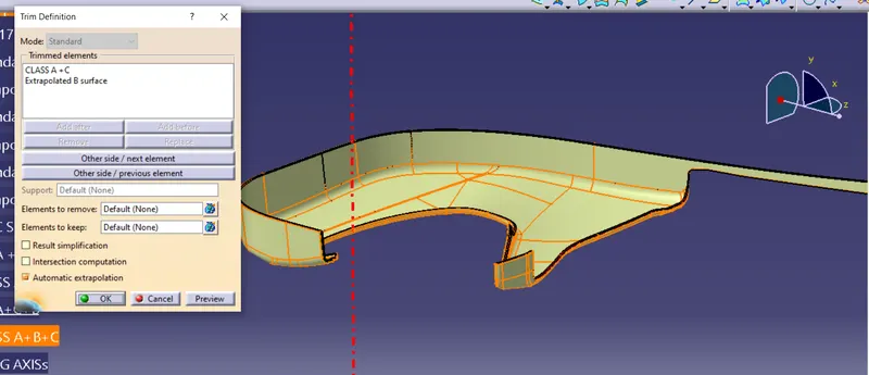
convert to solid
PART3: UPPER MAP POCKET
given A surface
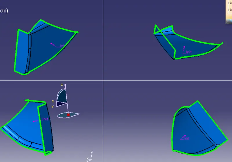
no boundry errors found
Creation of TOOLING AXIS
extrsct surface ., find midpont. and cordinate system
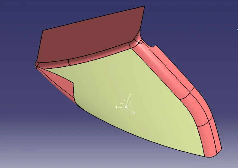
create intersection wrt YZ and find dummy tooling axis1
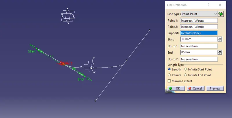
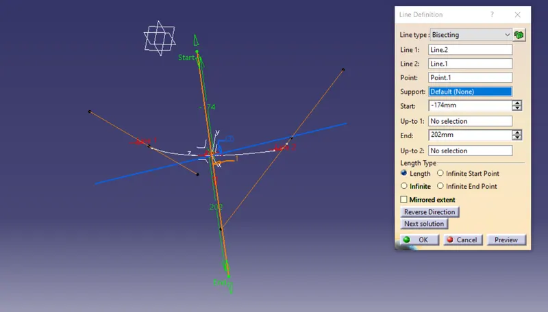
create intersection wrt YX and find dummy tooling axis2
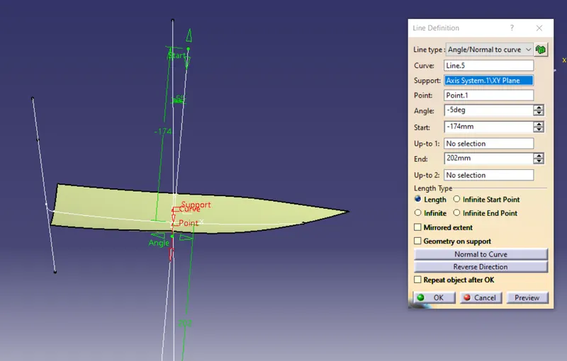
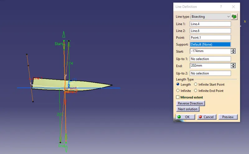
final TOOLING AXIS
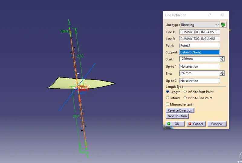
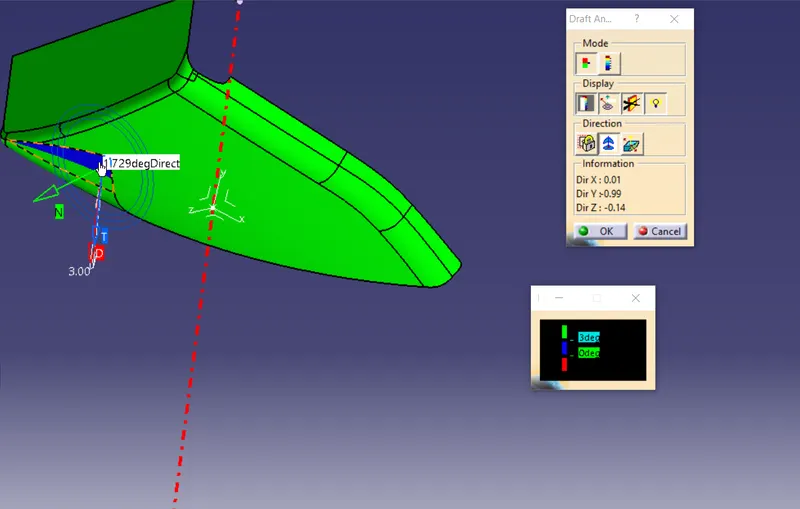
as there is a small deviation lets adust the centerpont along x axis and recreate dummy axis 1
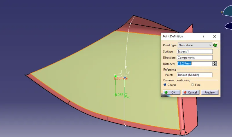
repeat the above procidure to create a tooling axis
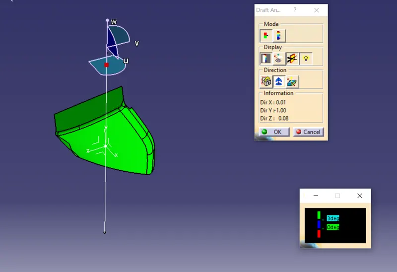
Creation of CLASS B SURFACE
extract aclass A surface and ofset by 2.5mm
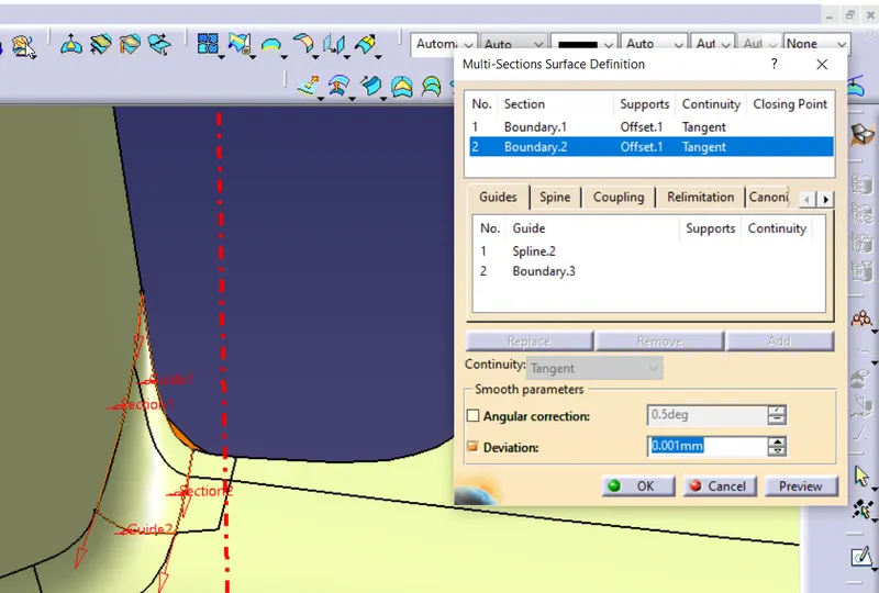
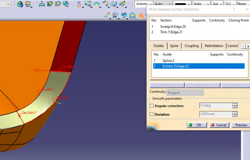
create spline with tangency,create multisection
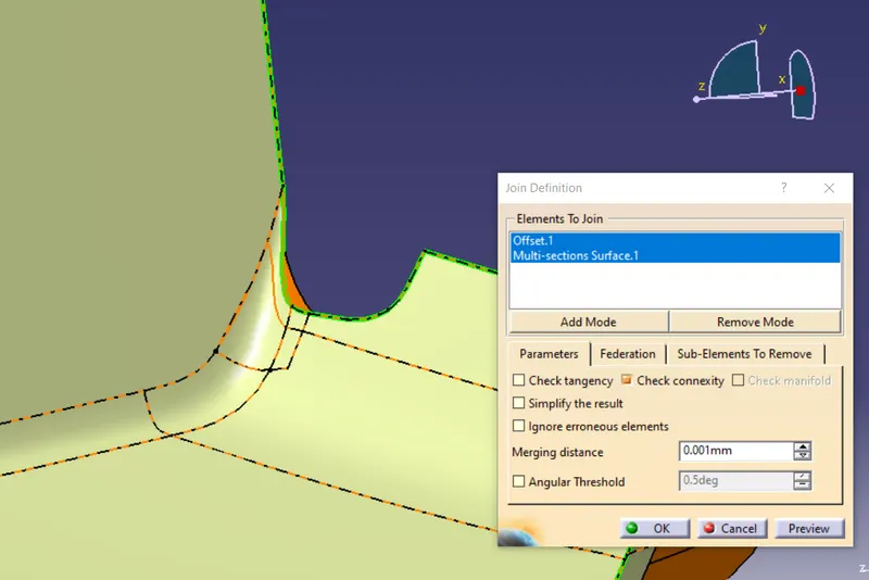
jointhe surface
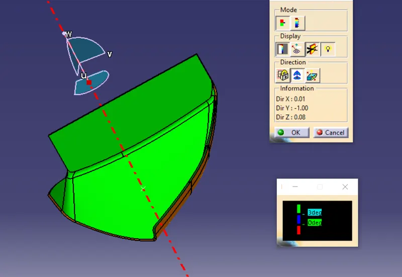
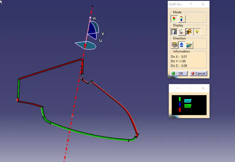
check draft. seems to satisfy
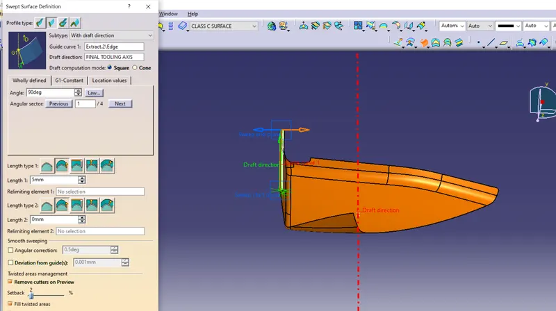
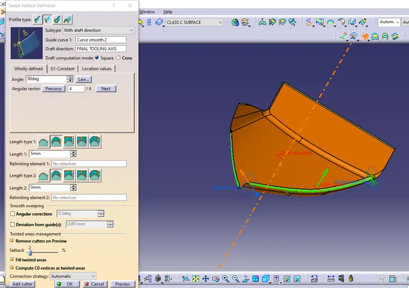
Creation of CLASS C SURFACE
parallel surface to tooling axis will have 90 sweep wrt tooling axis
Join class a and class c
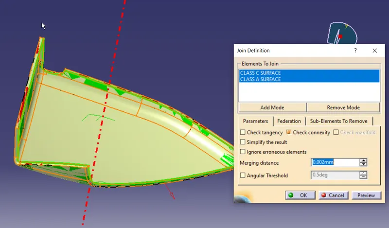
CLASS A+C+B JOIN
extrapolate b surface if required
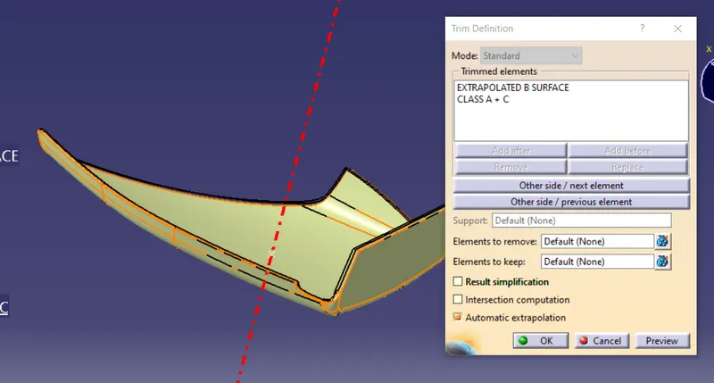
TRIM A+C and B
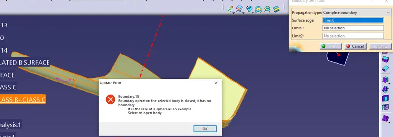
no boundry found
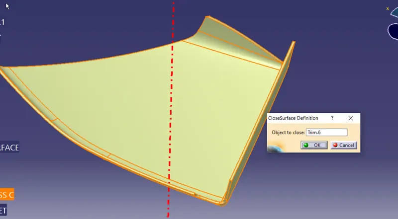
Convert to solid
PART 4: BOTTLE HOLDER
Given A surface
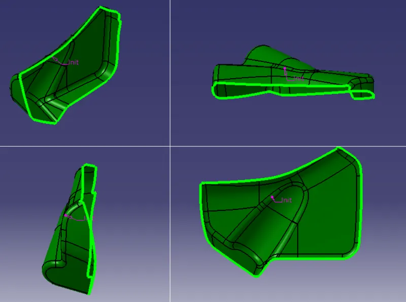
Tooling axis
extract a surface and find midpoint
create dummy axis 1 .
intersection curve wrt yx
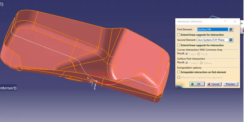
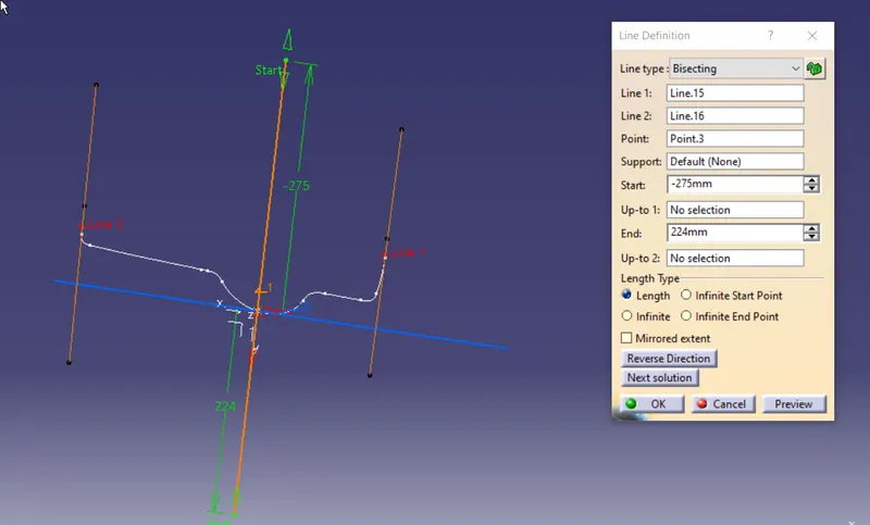
Dummy 2 axis
intersectin curve wrt yz
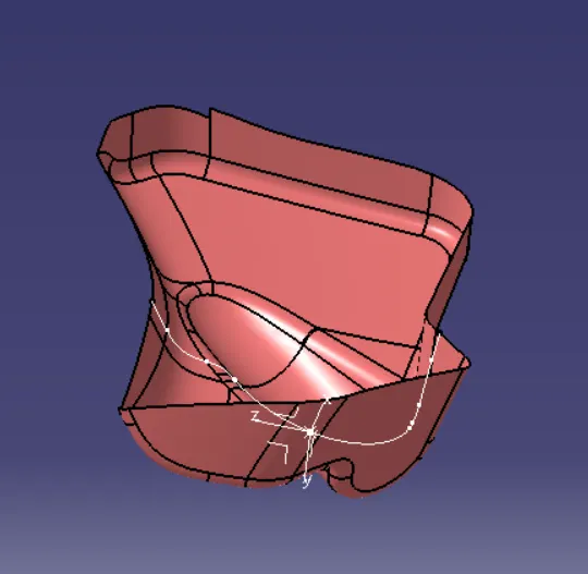
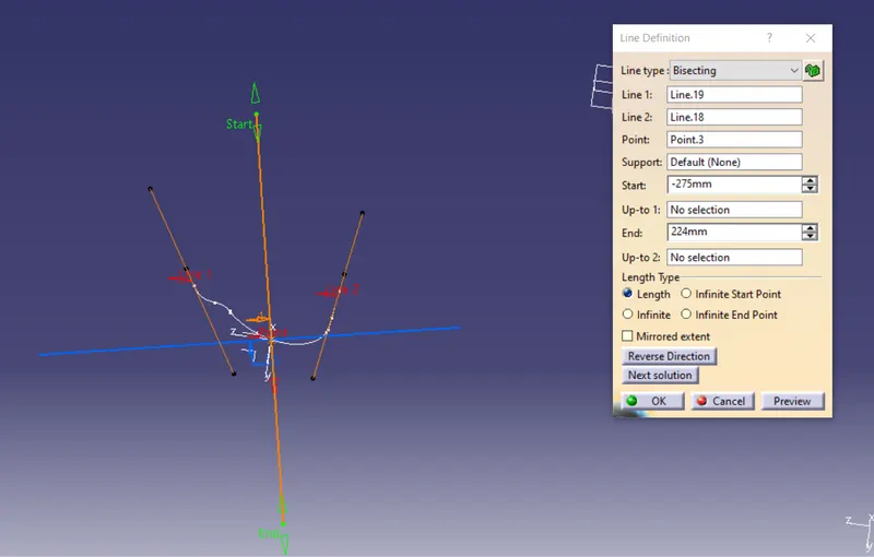
Final tooling axis
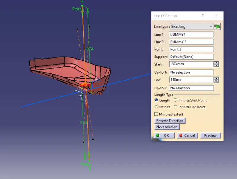
Draft analysis of classA
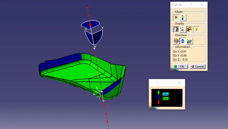
To be notted that the draft angle is not been satisfiying 3degree. so the data must be send back to the Class A surface designer
Lets assumme the given A surface is a pass by A surface engineer.
Creation of class b surface
extract surface and offset by 2.5
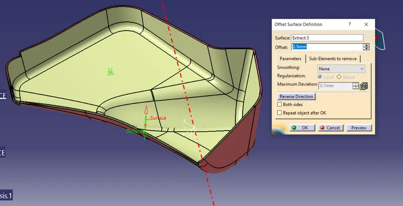
Creation of class C surface
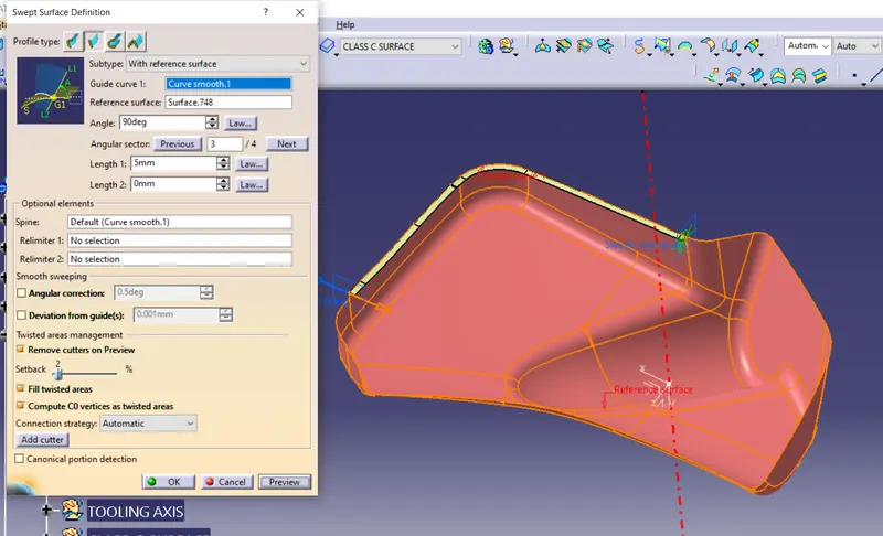
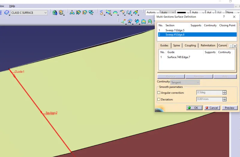
as all the c surface are formed on plane parallel to the tooling axis , the angle wrt to the surface can be considerd 90
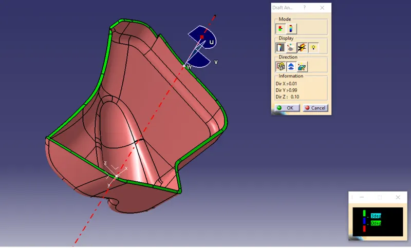
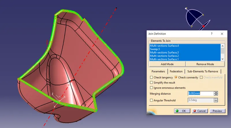
Creating CLASS A + CLASS C surface
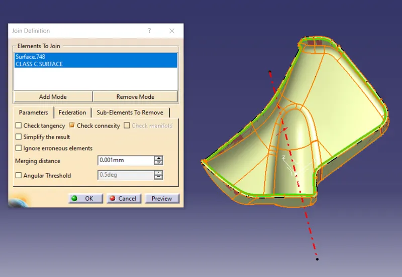
Creating closed surface
extrapolate B surface if nessosry
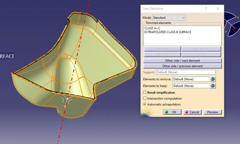
Check for boundry
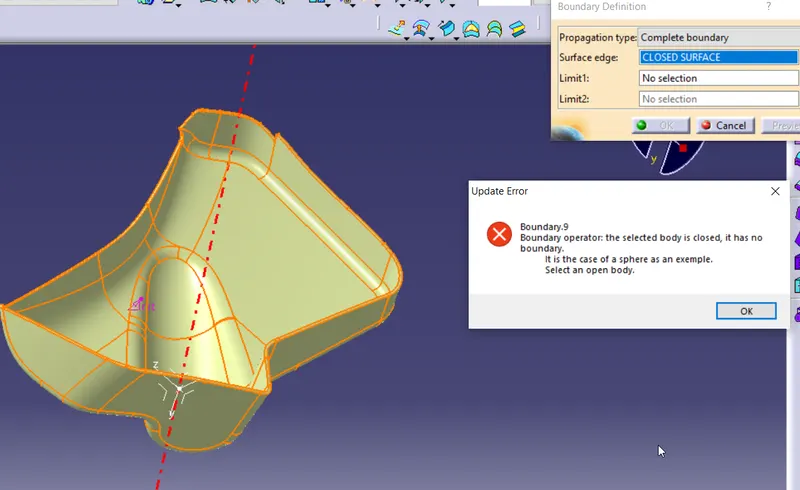
solid surface creations
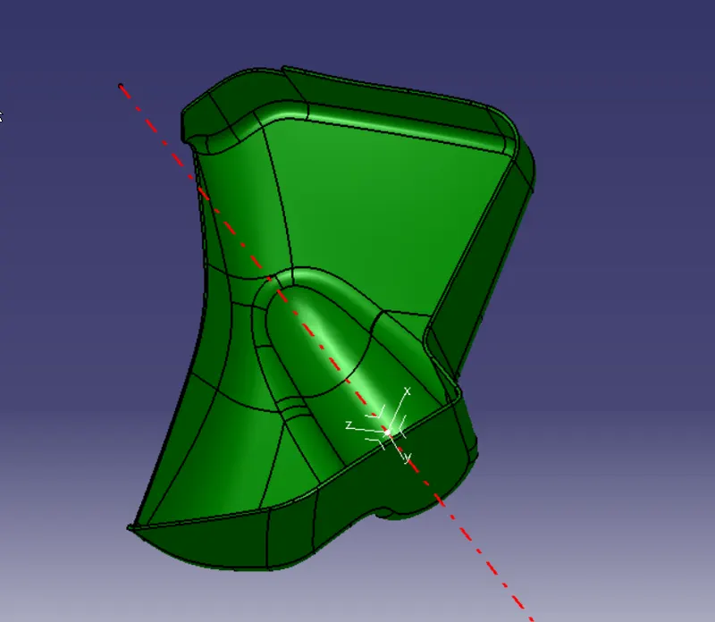
CREATION OF ENGINEERING FEATURES
Heat stakes
unhide mastersection to reveil the reference position of the heat stake to be placed
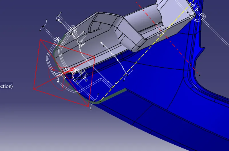
create a bosecting point wrt base of heatstakes and a plane normal to draft angle
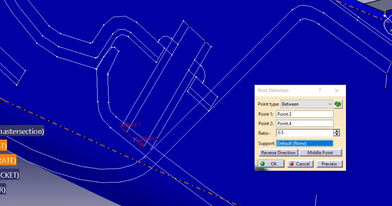
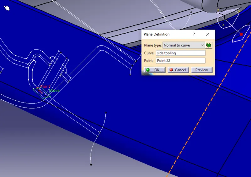
now create a sketch wrt the plane, taking end points of heatstakes as reference point dreaw circle and extude
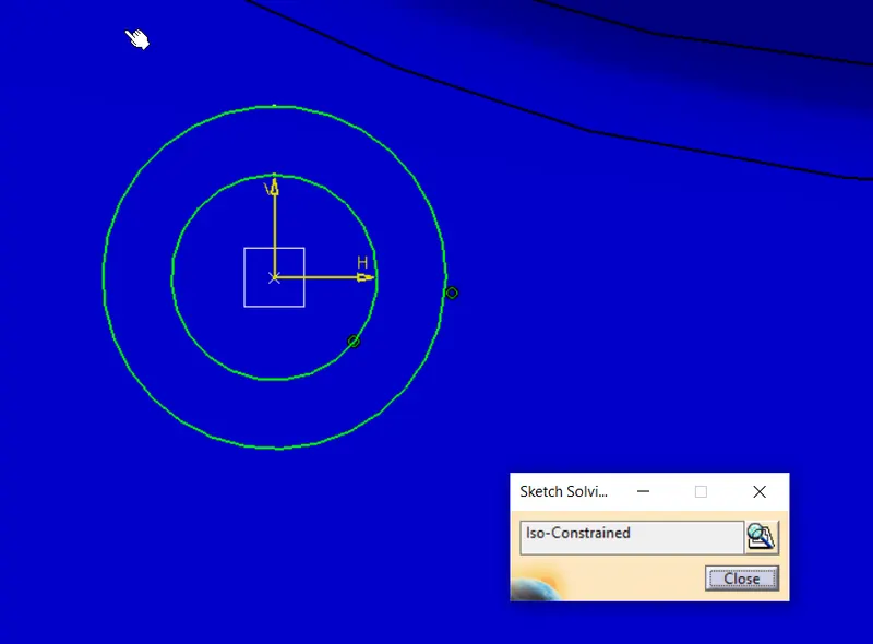
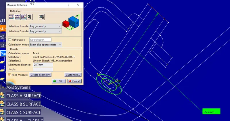
MEASURE THE HEIGHT OF HEAT STAKES AND PAD IT ACCORDINGLY , PROVIDE EXXES AT BOTTOM
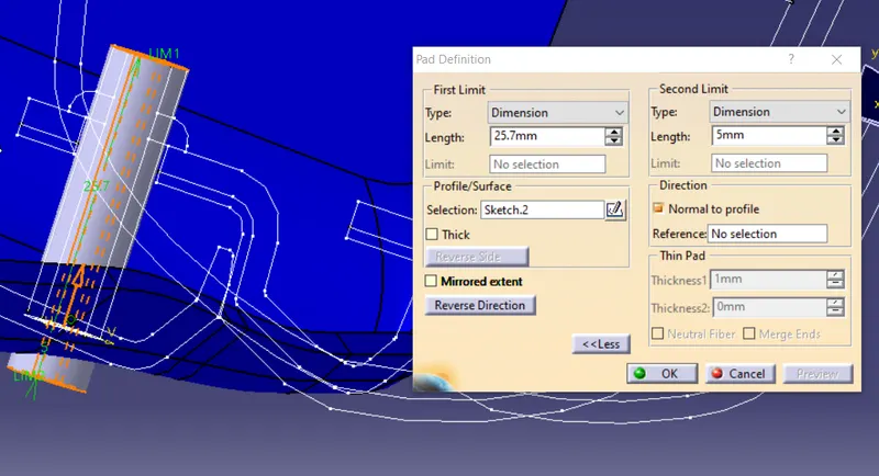
CREATION OF RIBS FOR SHEAT STAJ+KE
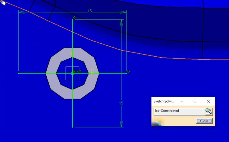
RIBS WITH 6MM HEIGHT AND 1MM THICKNESS IE,. 40% OF COMPONENT THICKNESS
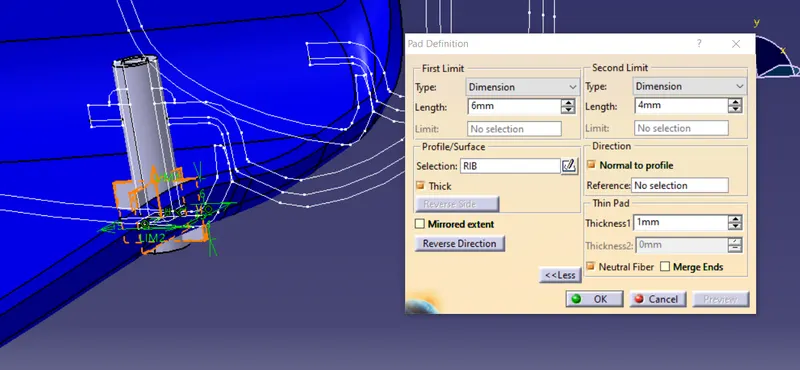
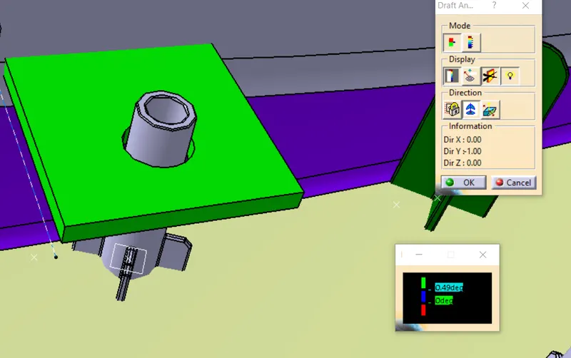
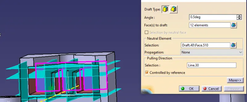
Addingg draft ,
as the componant is created on a plane normal to the tooling axis , and all the heats stakes are on same reference plane , draft angle of 0.5 can be provided to engneering surface before transslateing
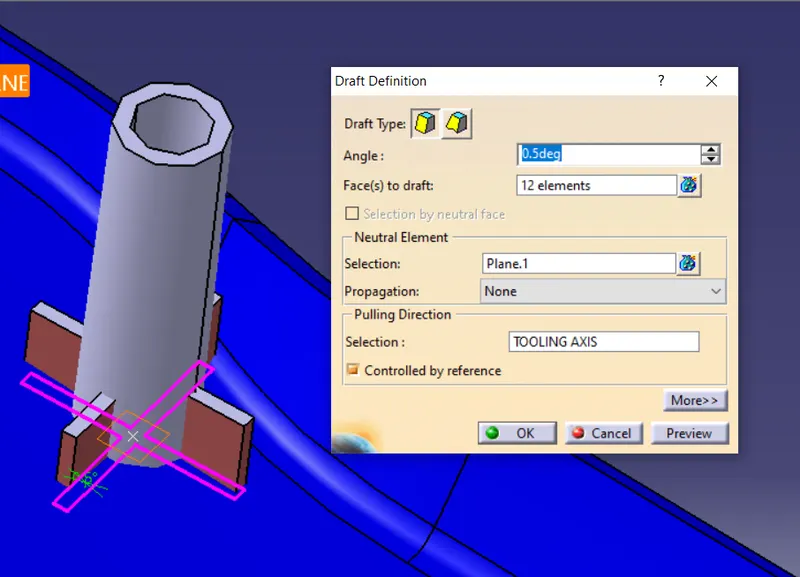
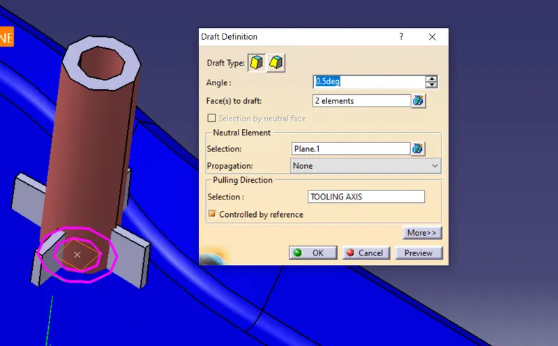
USE UNIUON TRIM TO JOIN THE RIBS WITH CYLYDER HEATSTAKE
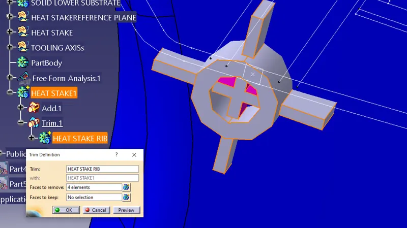
Add fillets and chamfer
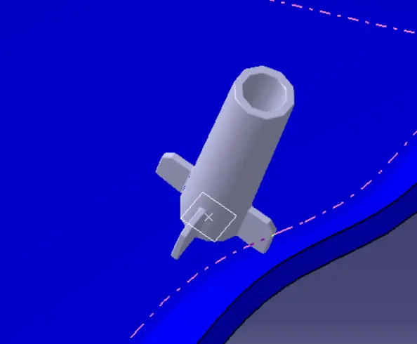
create a linr parallel to boundry to prplicate heatatakr.
project curve on plane
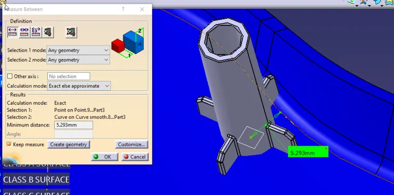
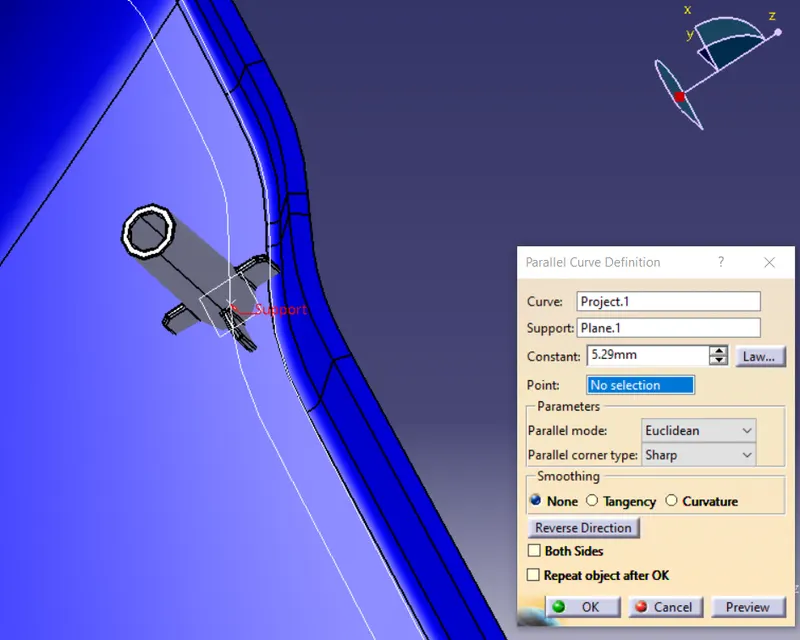
create points for translating heat stake
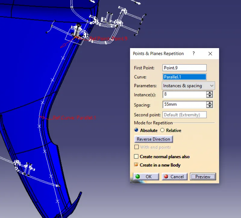
copy paste and transllate
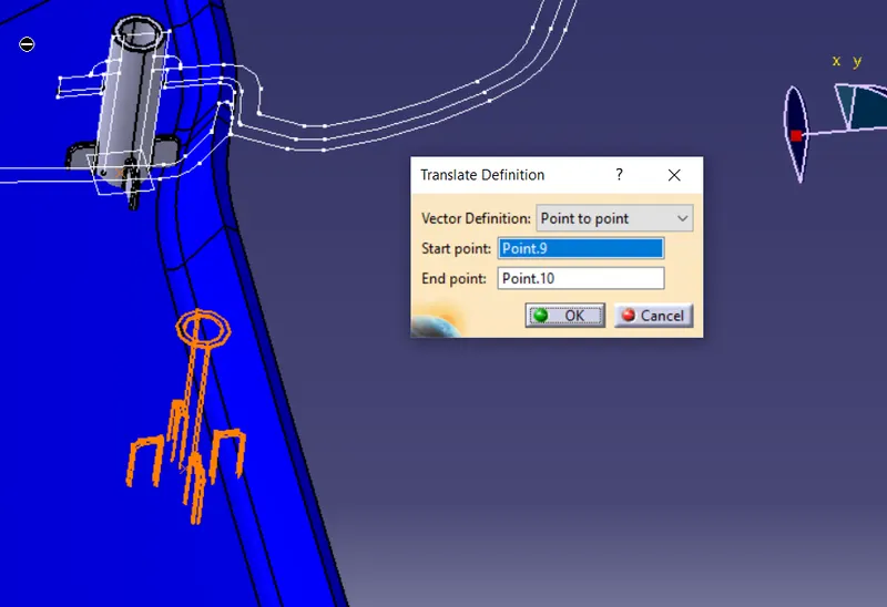
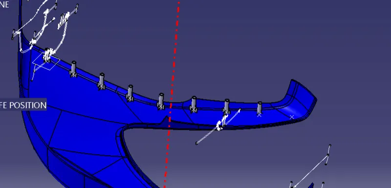
use similar procidure to add heat stakes where it is nessorry
stakes to support map pocket
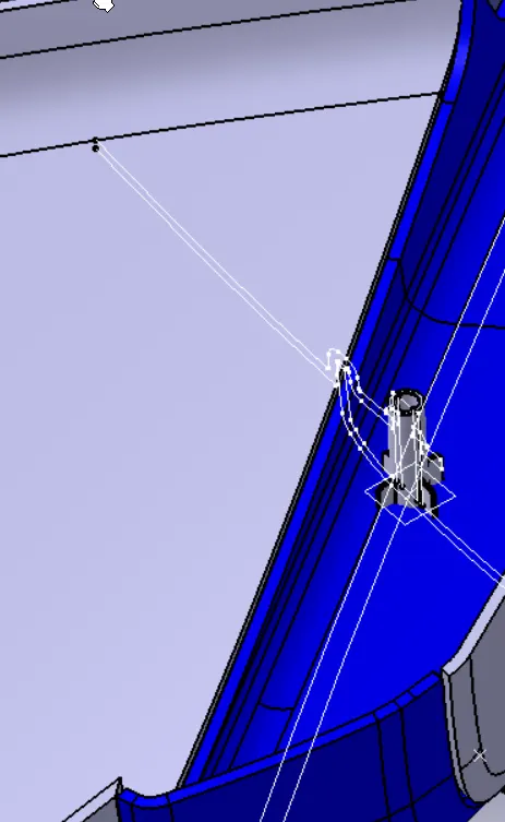
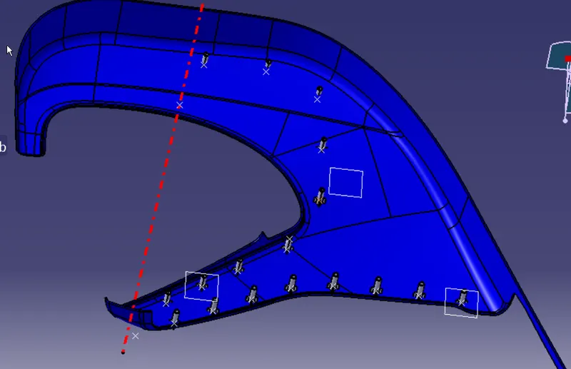
isolate the points and move it to give a proper structure
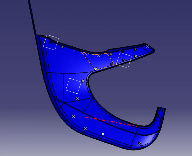
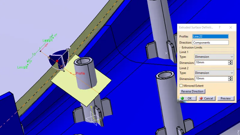
CREATION OF FLANGE
Armrest
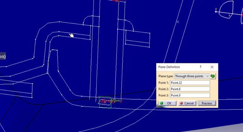
create a plane
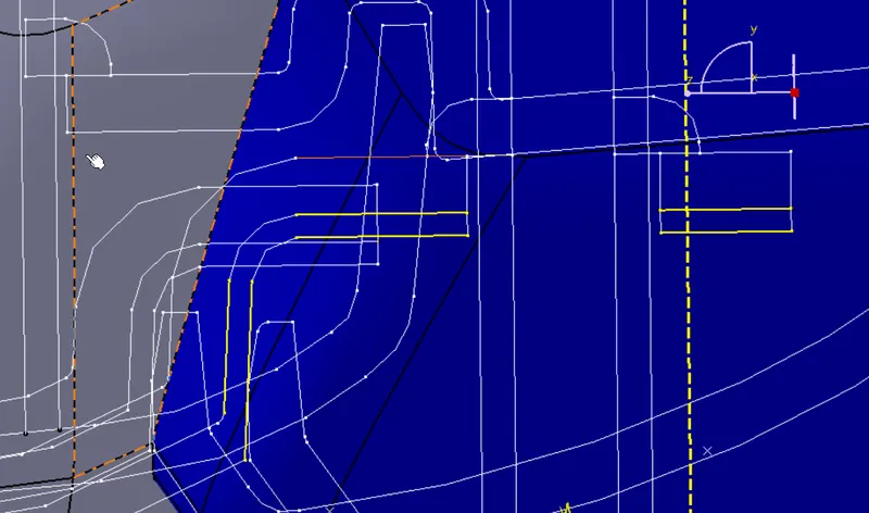
get extract from master section
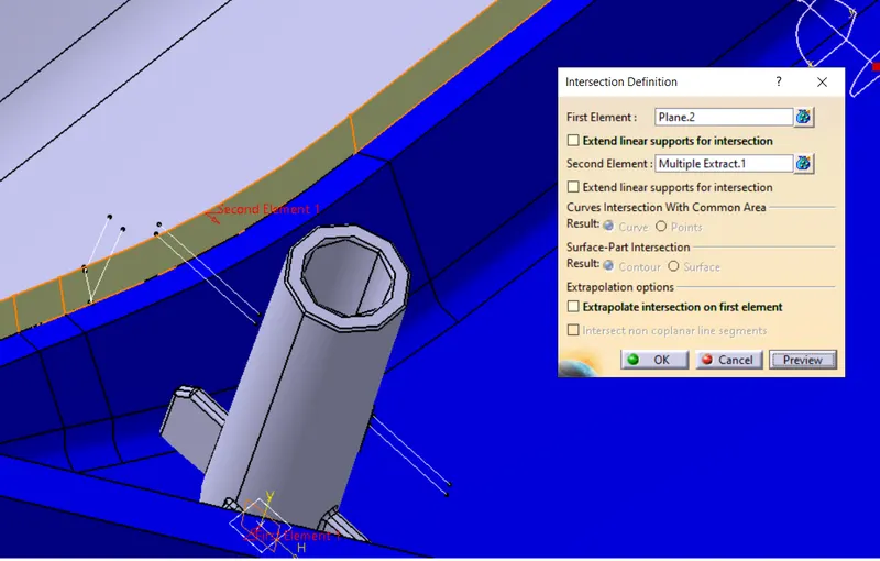
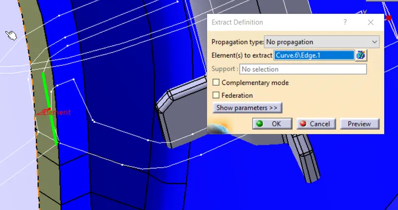
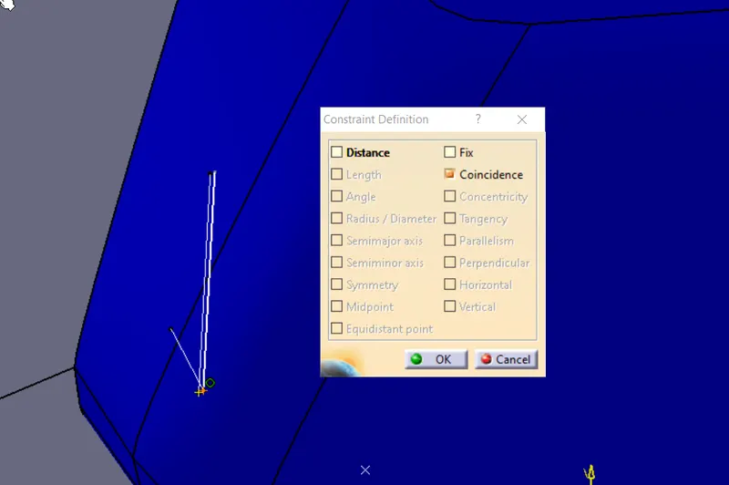
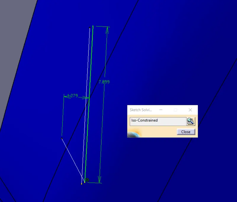
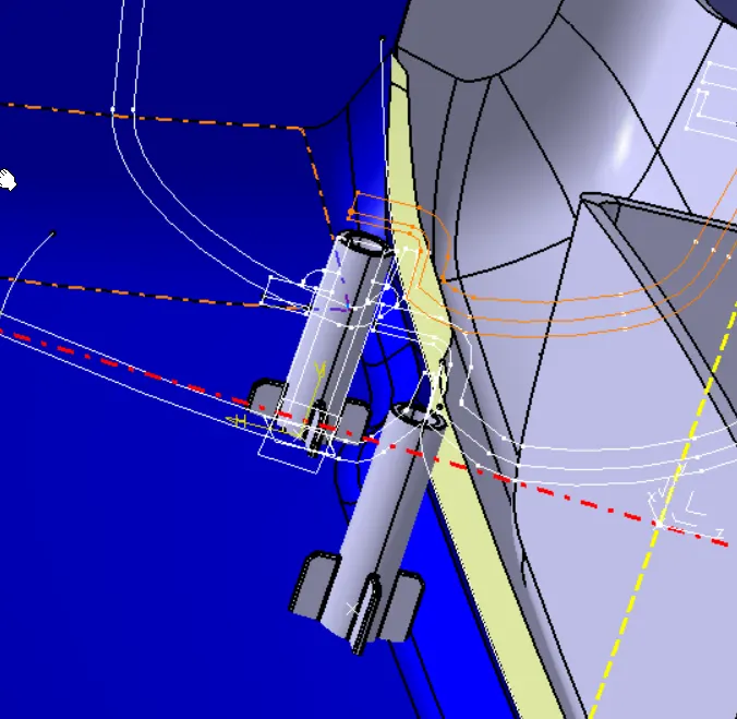
create another flange where the heat stajes rest
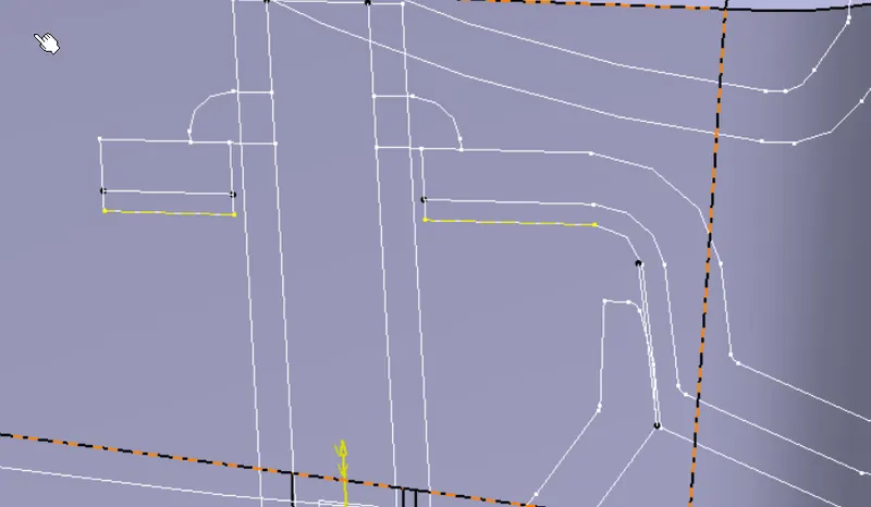
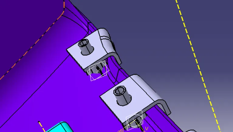
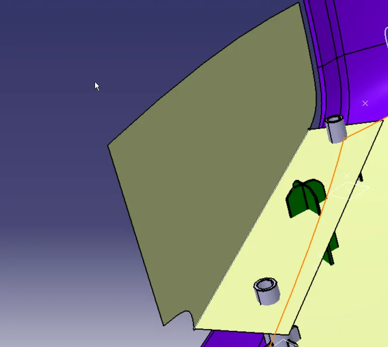
hole and draft
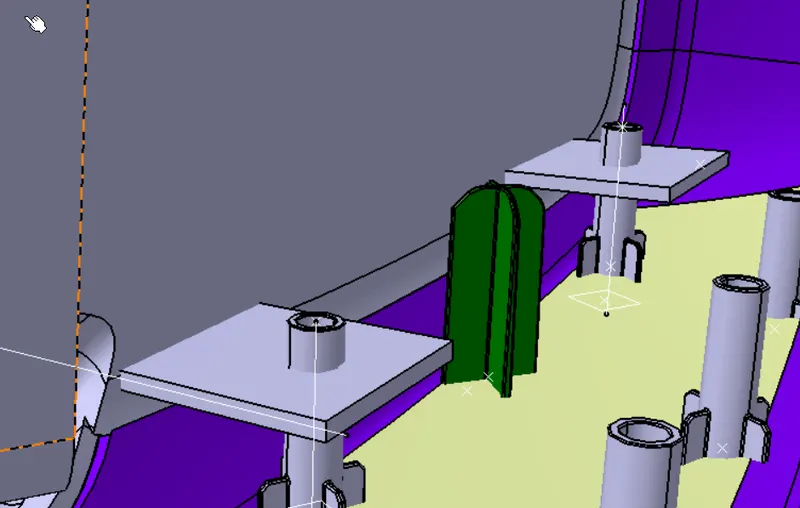
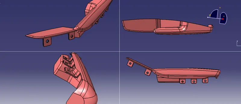
CREATING FLANGE ON UPPER MAPPOCKET
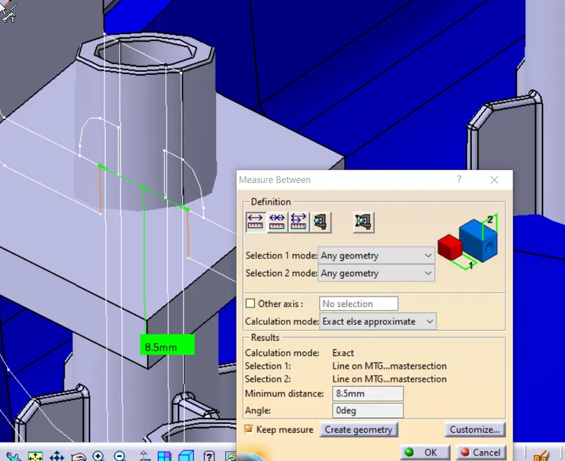
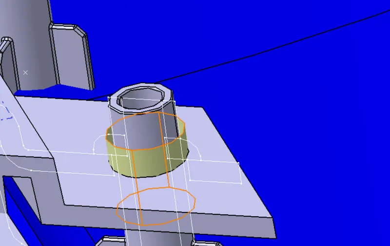
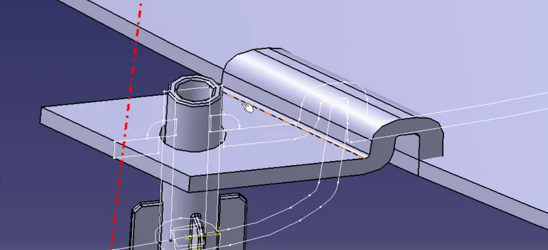
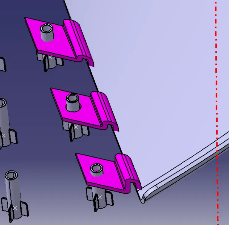
bottle holder flange
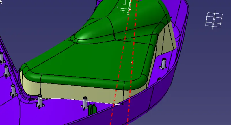
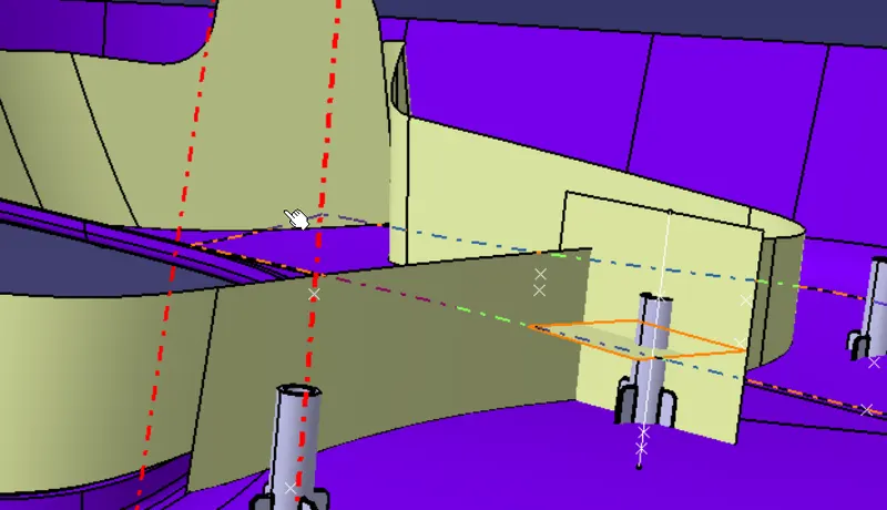
APPLY DRAFT
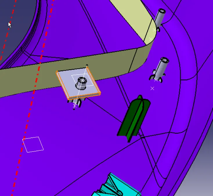
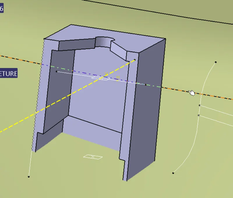
DOG HOUSE CREATION
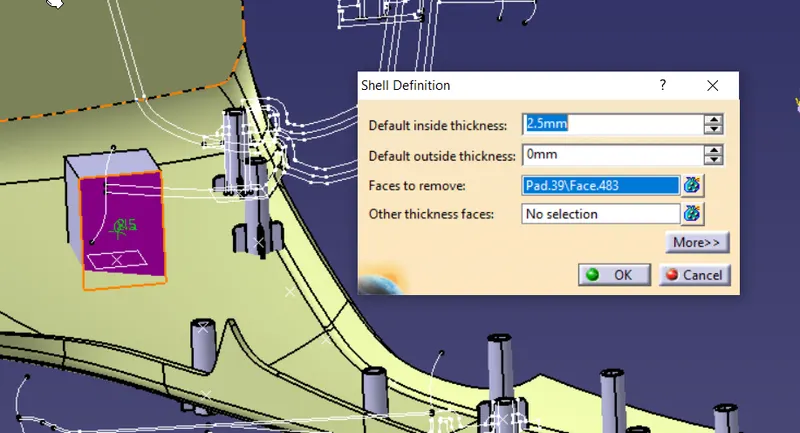
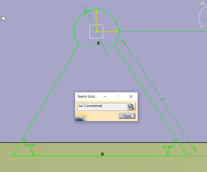
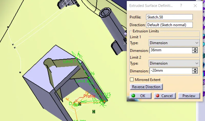
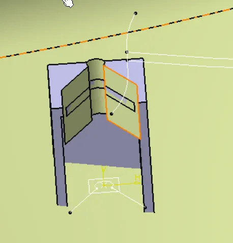
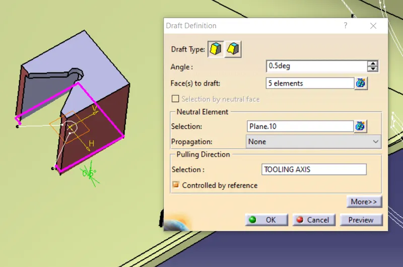
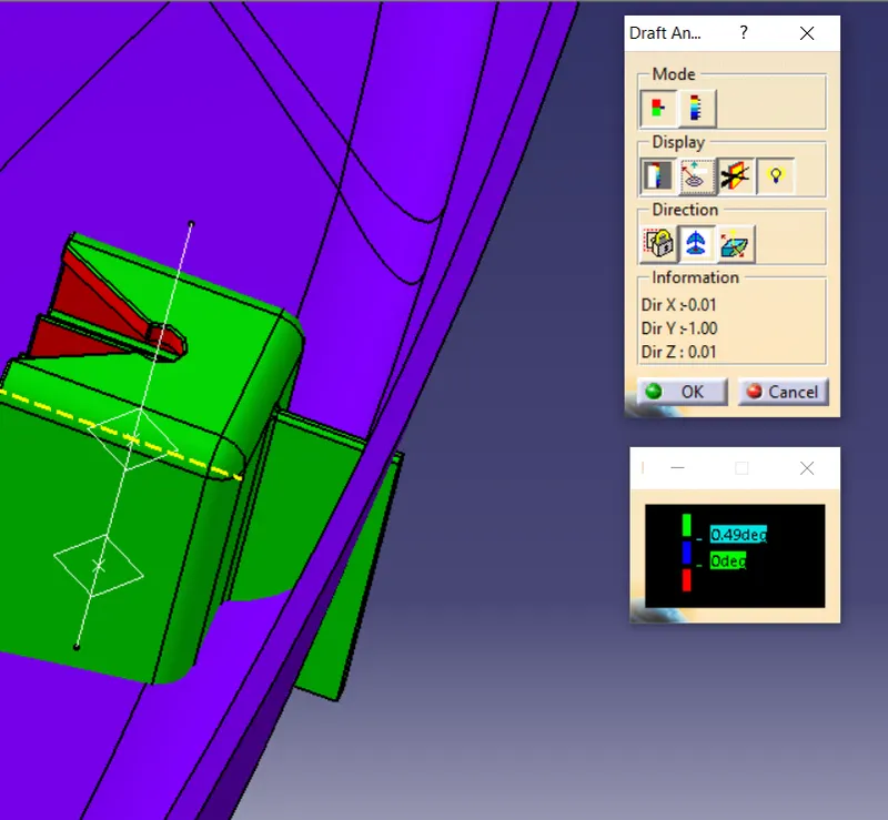
SIDE TOOLING AXIS
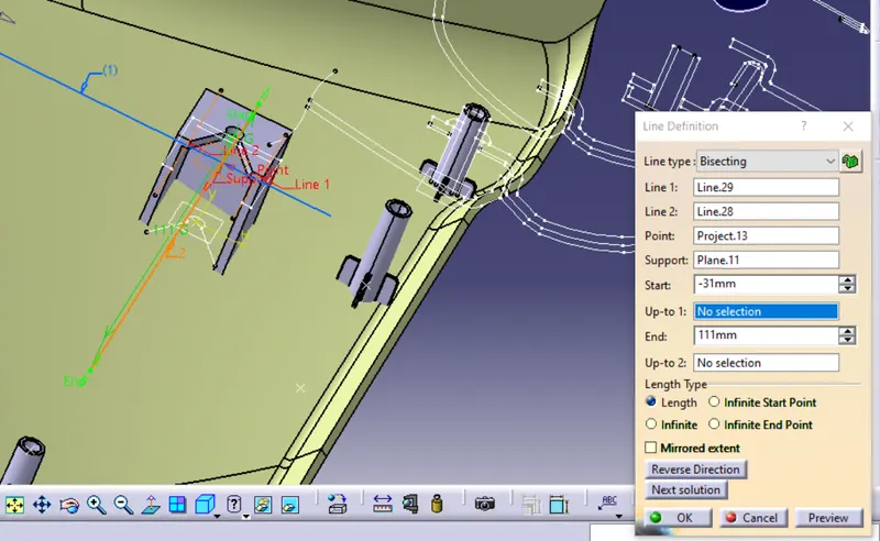
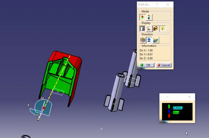
SECOND
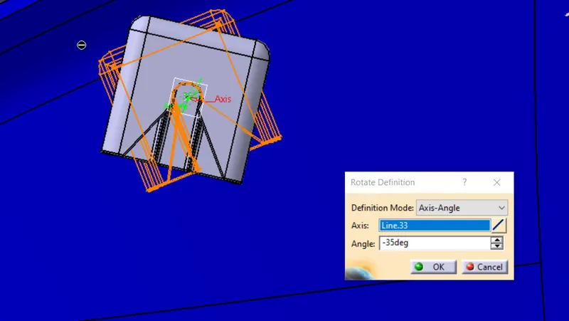
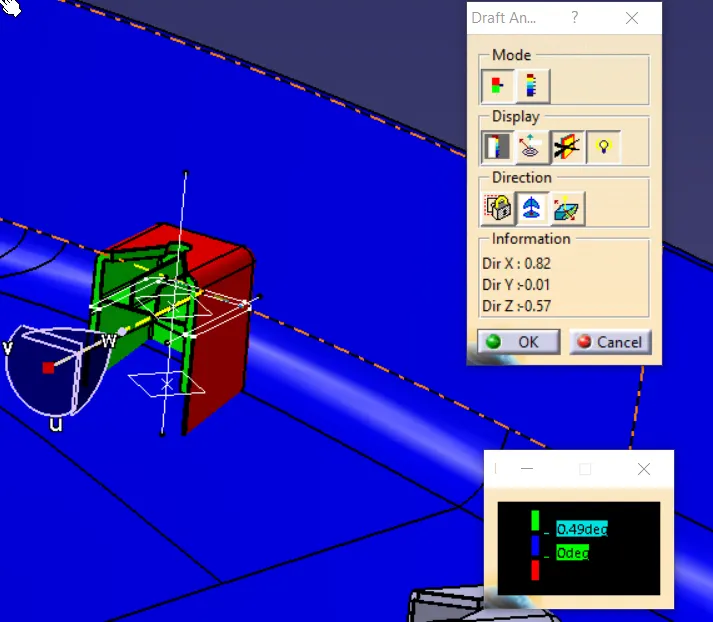
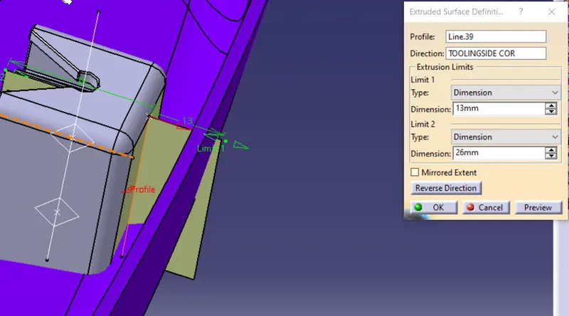
CREATION OF LOCATORS
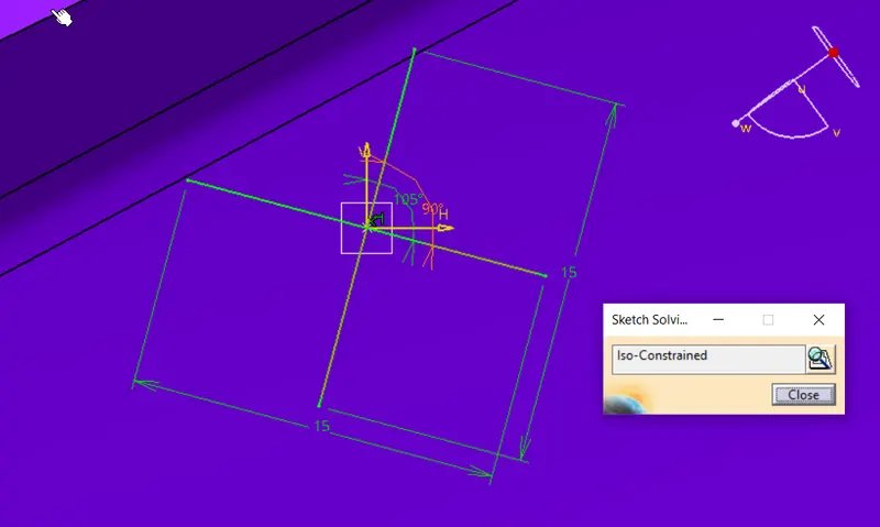
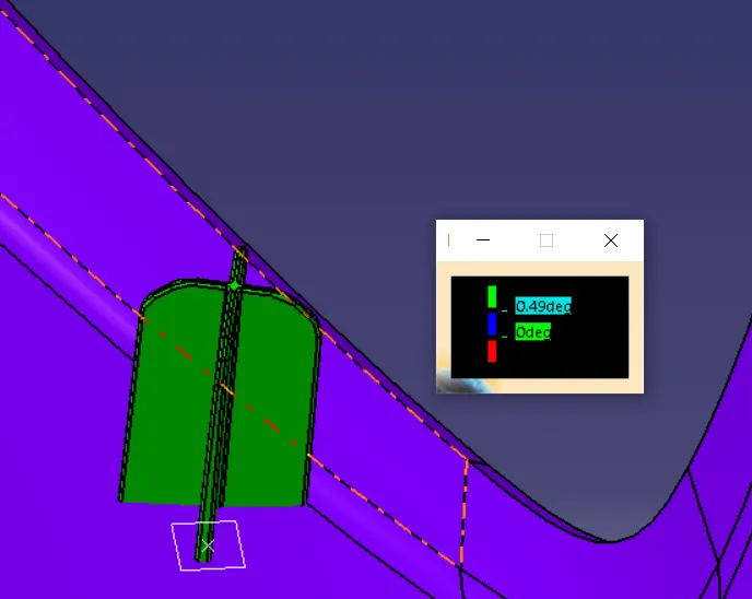
LOCATOR2
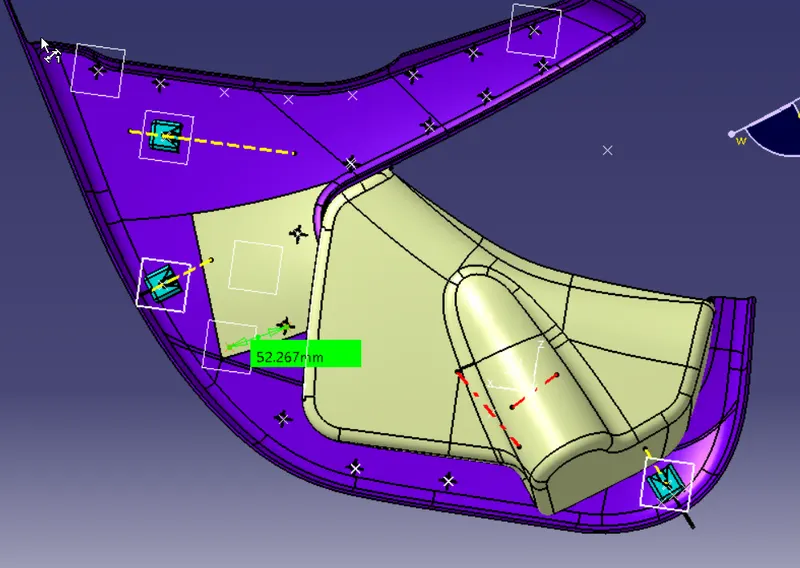
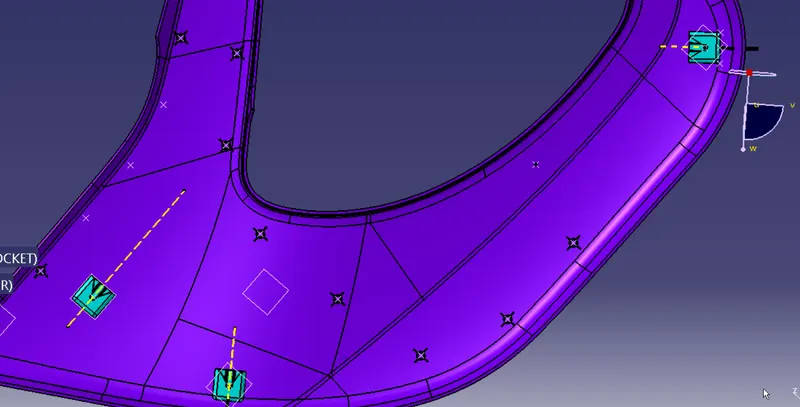
Create point copy , paste and translate to required position
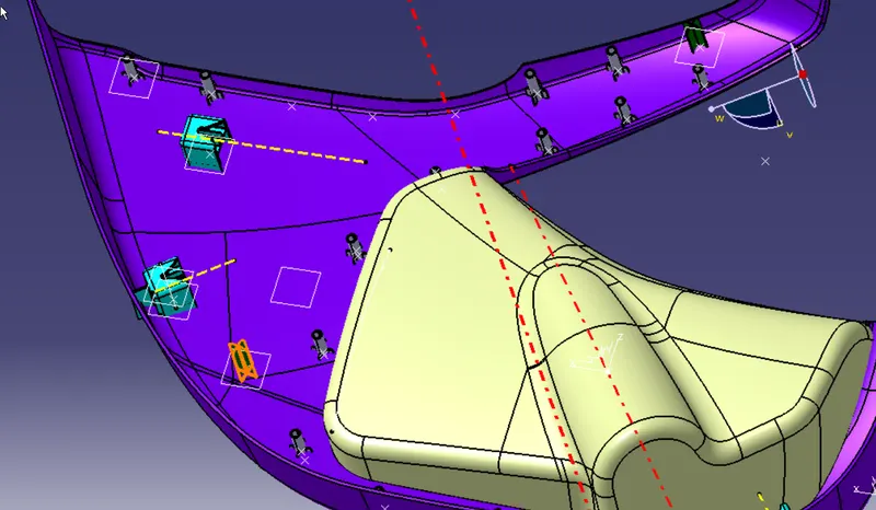
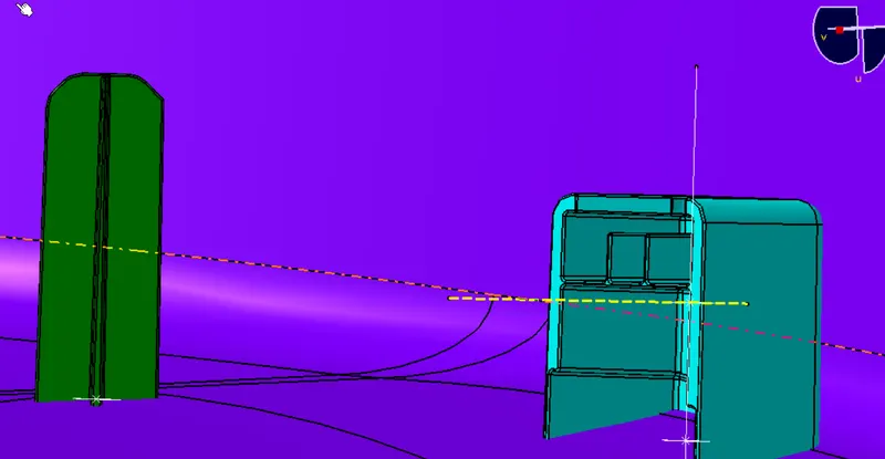
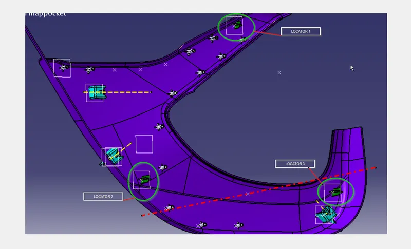
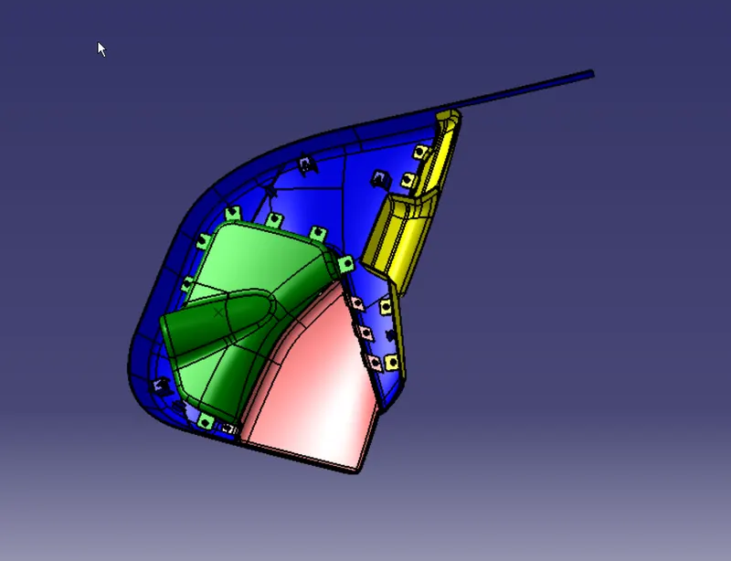
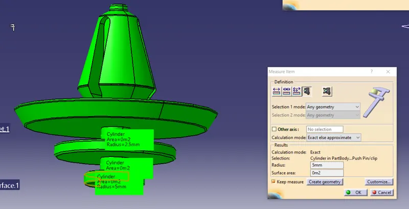
ASSMBLE PUSH PINS
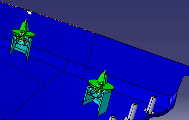
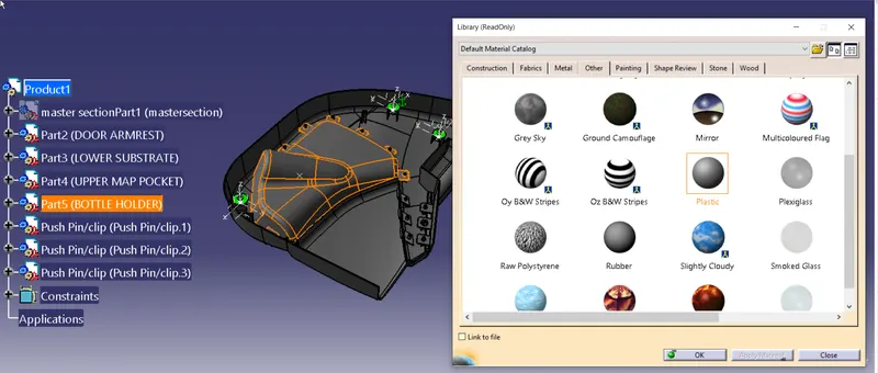
adding material properties to parts