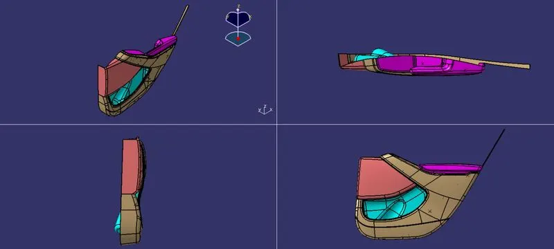
Final project - Side Door Trim Assembly
OBJECTIVE
Design and assemble individual components of the Door Trim panel along with different engineering features taking reference from the master sections.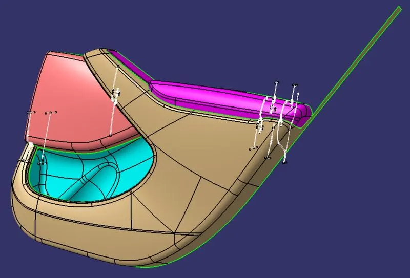
PART 1: LOWER SUBSTRATE
1. Defining a Tooling axis for the Class-A surface
- Step 1: Check the connectivity of the surface and ensure there is no gap in the class A surface. The boundary command helps by highlighting the boundary of all the edges thus we can visually check for gaps in the class A surface.
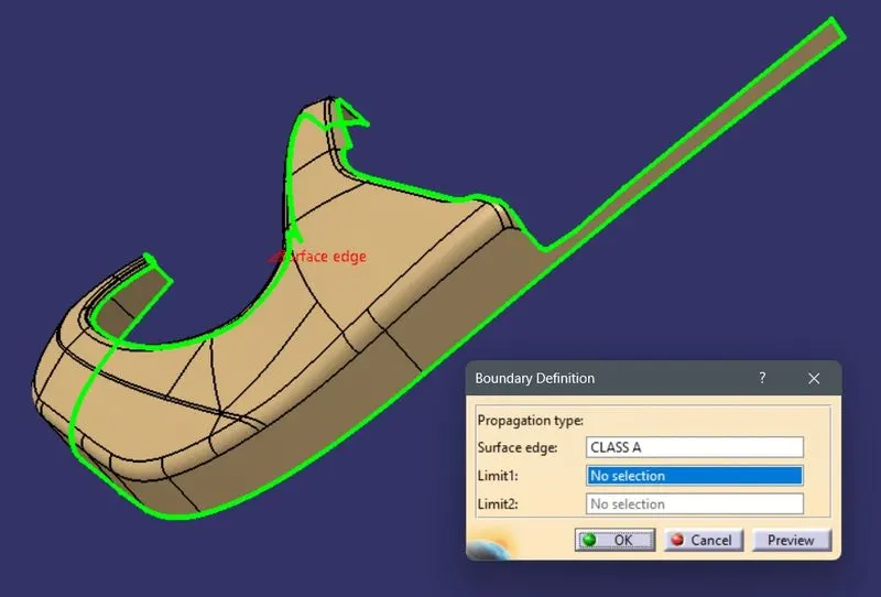
- Step 2: We observe the surface from all three axes to find the optimum tooling axis. Here the Y axis can be the tooling axis.
- Step 3: We create a point at the CG of the body and create a line along the Y-axis. This is our main tooling axis.
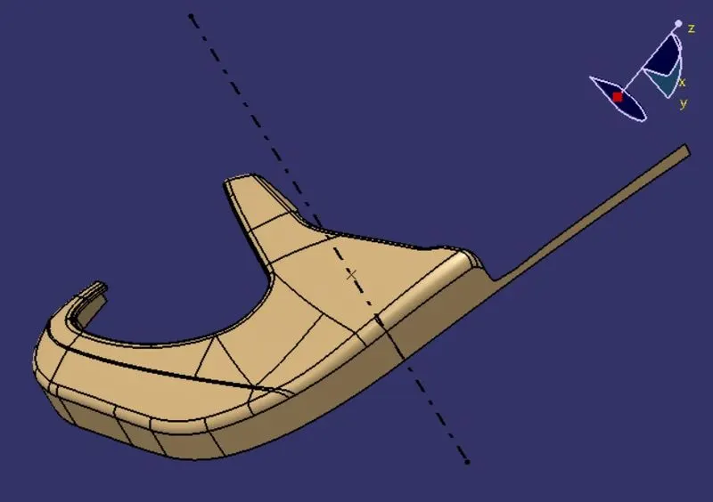
- Step 4: We perform a draft analysis on class A and check the angles of the surface we think will create problems in tooling.
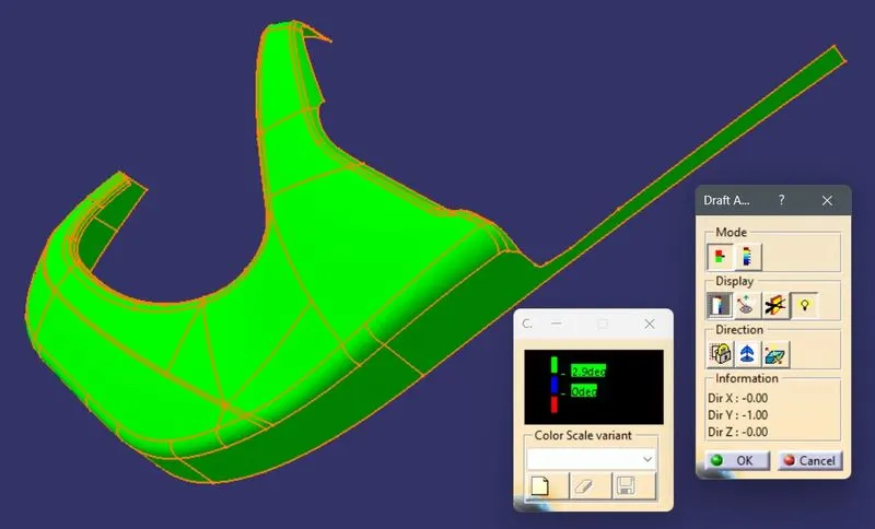
2. Creating Class B surface
- Step 1: We measure the thickness from the master section which is 2.5 mm.
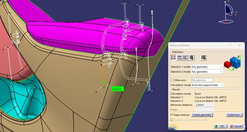
- Step 2:We directly offset the class A for 2.5 mm and extrapolate the whole boundary for 5mm to get the class B surface.
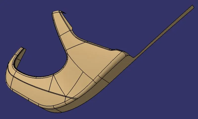
3. Creating Class C surface
- Step 1: We use the boundary command to extract the side edge boundaries into 6 different boundaries.
- Step 2: We sweep with reference surface to create a surface at 90 degrees where it doesn't need clearing for 4mm.
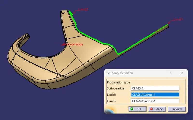
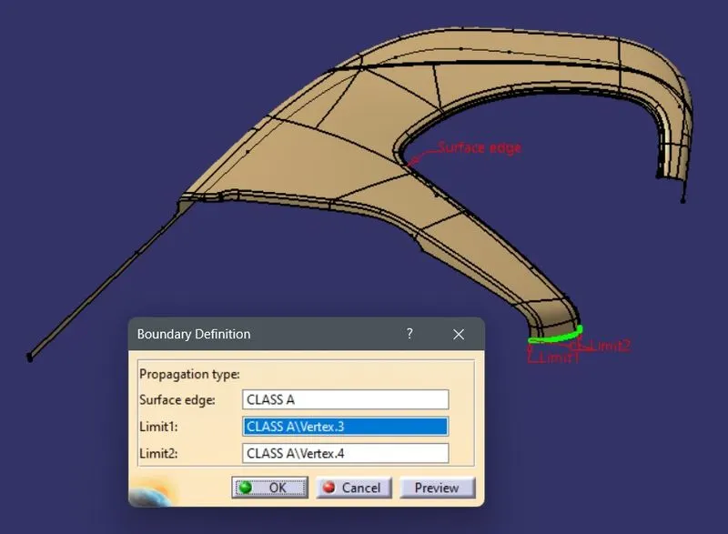
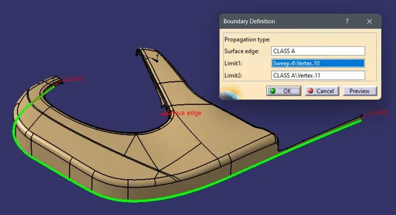
- Step 3: We sweep along with the draft direction as the main tooling axis to create a surface at 3 degrees where it needs clearing for 4mm.
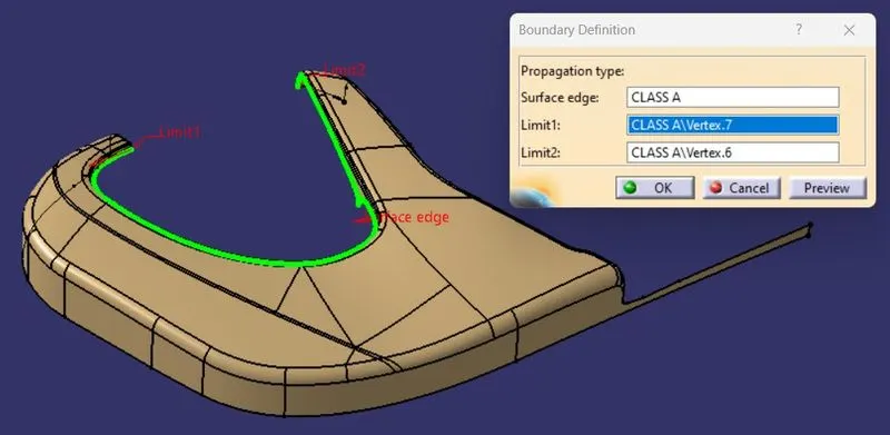
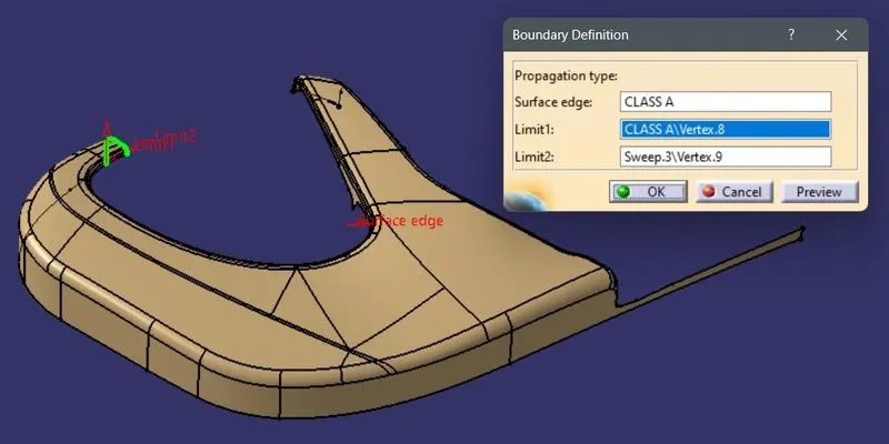
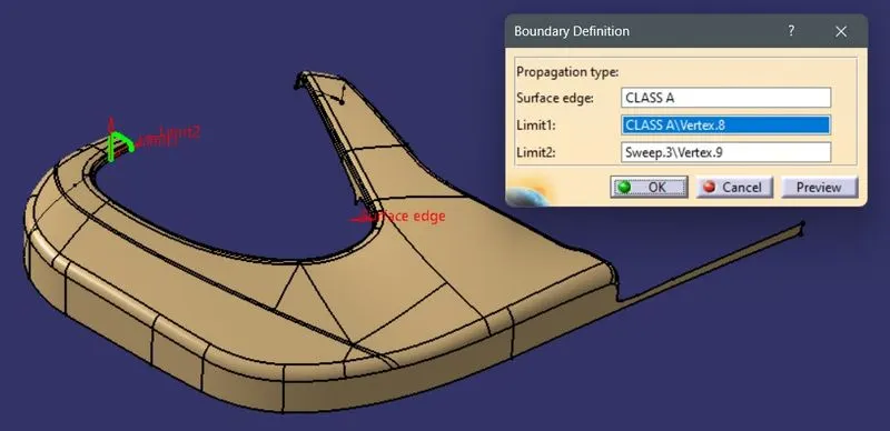
- Step 4: We extrapolate the ends of the above surface and trim all 6 sweeps together to create the final C surface.
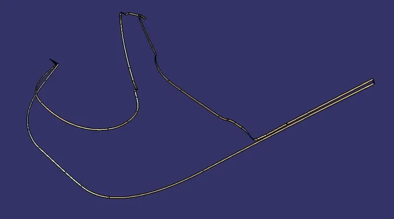
4. Creating the closed volume
- Step 1: We use the join operation to join the Class A, and C surfaces and trim them with Class B surface into one body to get the final surface body.
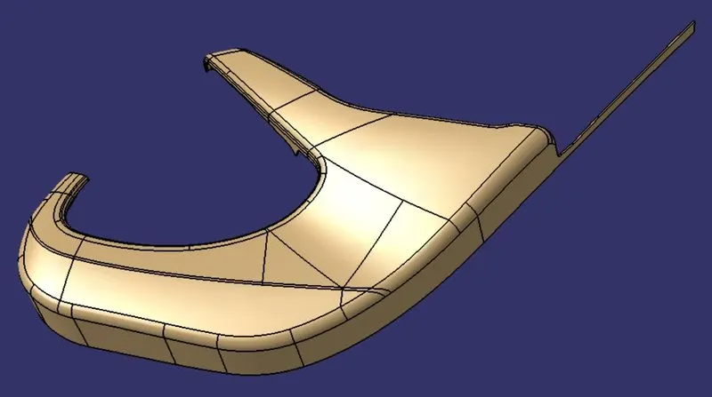
5. Creating the plain solid part
- Step 1: We use the closesurface command in the part workbench to get the solid part.
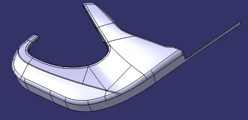
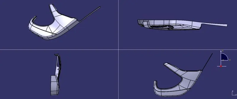
all views
6. Creating the 4-way locator
- Step 1: We create a point on the A surface where we want the 4-way locator and create a plane offset from the ZX plane at that point.
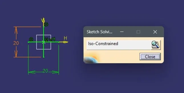
- Step 2: We create a positioned sketch of the 4-way locator for 20mm.
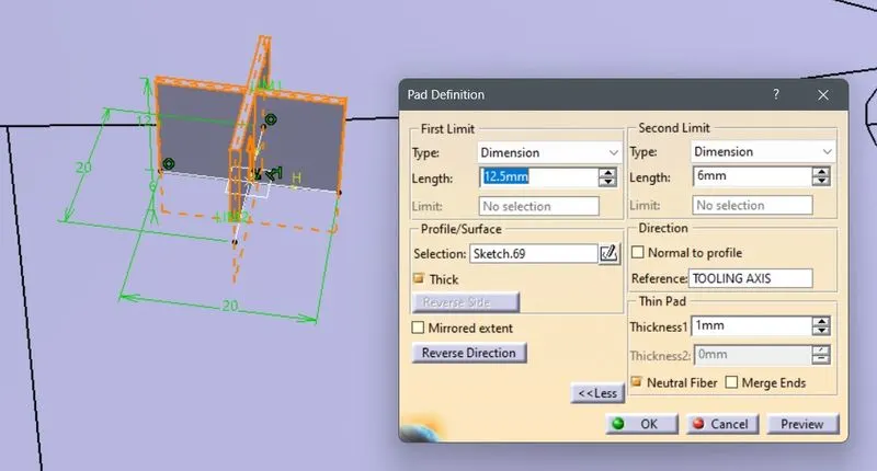
- Step 3: We then pad the sketch with thick for 1mm wrt the neutral fiber for a height as per the design rule for ribs i.e., <=5T.
- Step 4: We draft the surfaces along the tooling axis for a minimum of 0.5 degrees and create a chamfer of 5 mm and edge fillet with R=0.25mm.
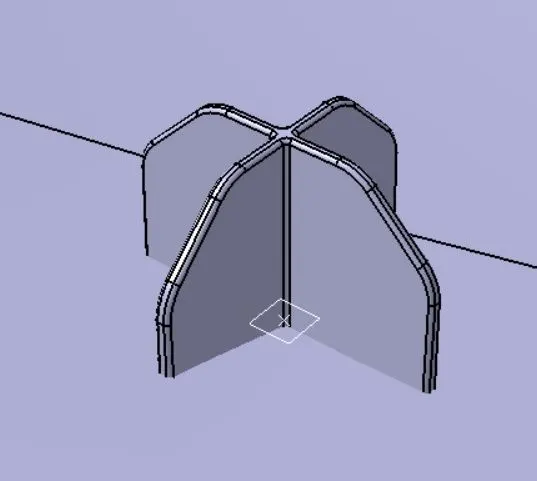
- Step 5: We copy and paste to create a duplicate of the 4-way locator in a new body and translate it to the required place and union trim with the main part to assemble the locators.
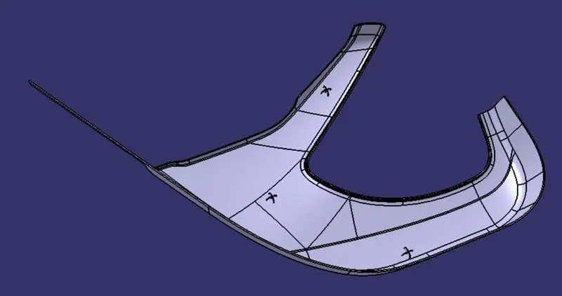
7. Creating the heat stakes
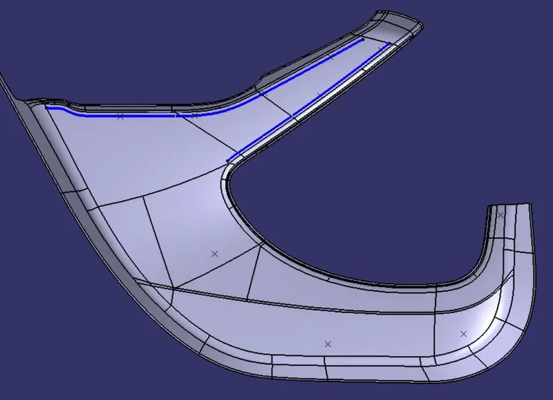
- Step 1: We extract the surface from the lower substrate part and create a boundary of the required edge. We create a curve parallel to the edge and create points for the heat stakes.
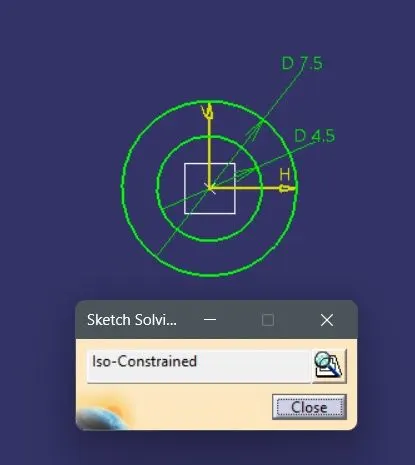
- Step 2: We create a positioned sketch of the heat stakes with ID=4.5mm and OD=7.5mm as measured from the master section.
- Step 3: We then pad the sketch for a height as in the master section.
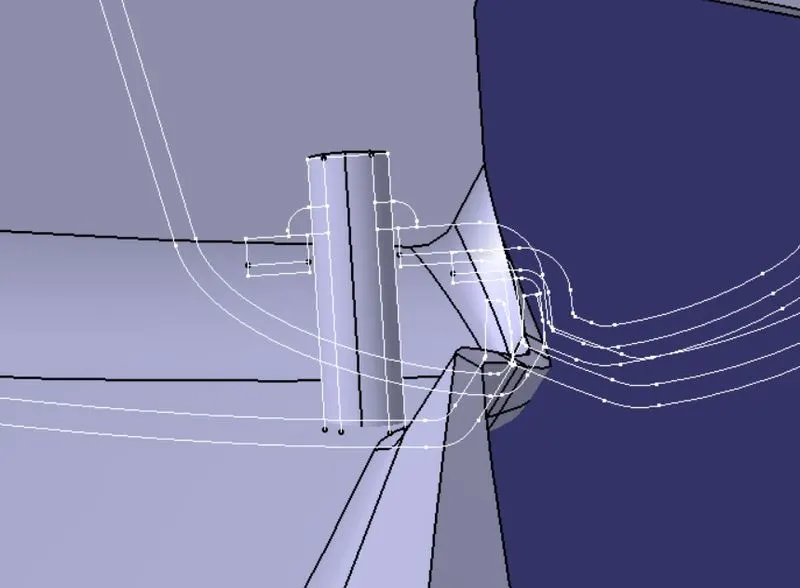
- Step 4: We draft the surfaces along the tooling axis for a minimum of 0.5 degrees and edge fillet with R=0.25mm.
- Step 5: We then create supports as we created the locator and union trim with the circular pad and edgefillet with R=0.25 to get the heat stake.
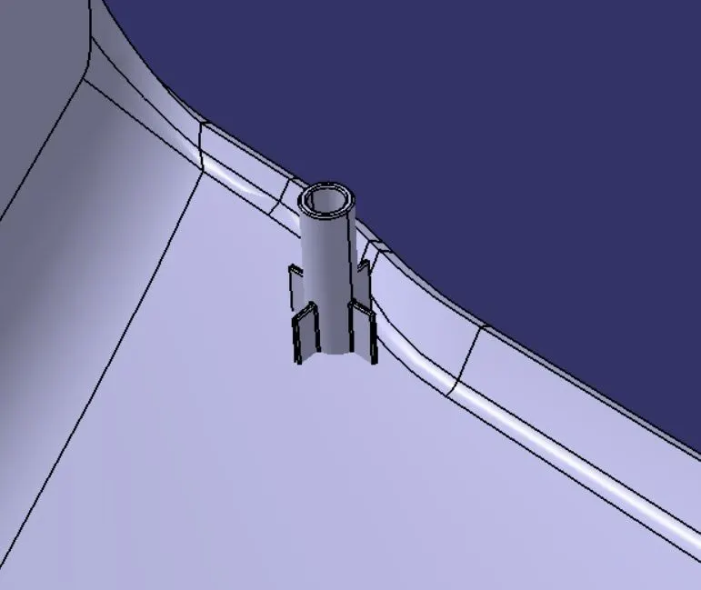
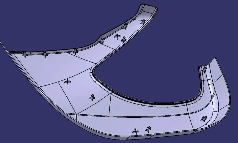
- Step 6: We copy and paste to make duplicates of the above heat stake and translate them to all the reference points and do the final union trim with the part body to assemble them.
8. Creating the Dog house
- Step 1: We create a point on the part where we want the 1st dog house and create a plane offset from the ZX plane at that point.
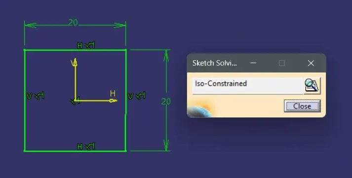
- Step 2: We create a positioned sketch of a dog house base block of 20 x 20 mm and create the pad for 25 and 7mm. We draft 3 side faces along the main tooling axis for 3 degrees.
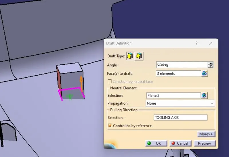
- Step 3: We shell the front and bottom surfaces for 2.5mm.
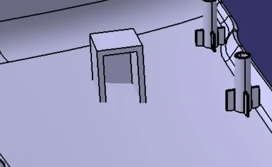
- Step 4: We create a line normal to the front surface. This is the side core axis.
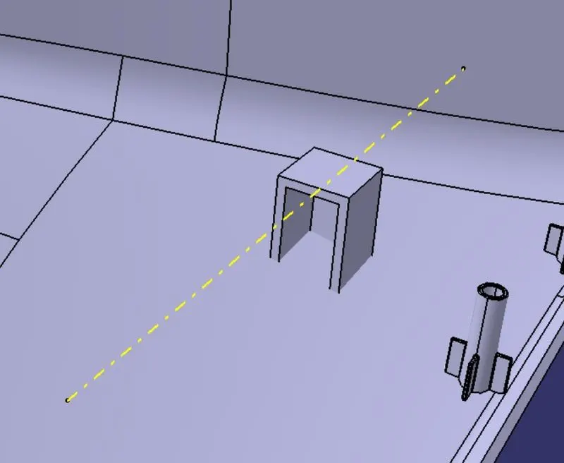
- Step 5: We draft the inside surfaces for 0.5 degrees along the side core axis.
- Step 6: For the coring, we take the intersection between the dog house and the lower substrate and extrude and offset it by 3-6 mm. extract the inside surface and offset it for 0.6T (1.5mm). We also extract the inside surface of the doghouse, offset it for 0.6T (1.5mm), and trim it with the extruded surface to get the coring snipping surface.
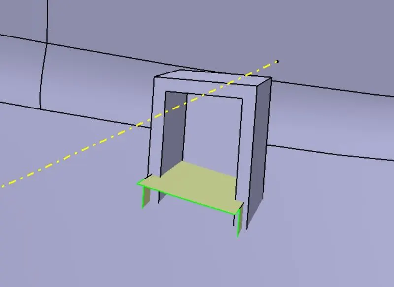
- Step 7: In the part workbench, we snip the doghouse by the above surface to get the coring.
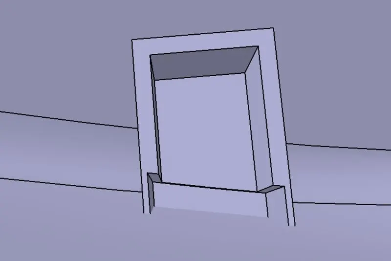
- Step 8: We create another sketch for the locator's ribs. We pad and thicken it with a thickness of 1 mm and create edge fillets and union trim with the dog house canopy. A draft of 0.5 degrees is also provided along the side core axis.
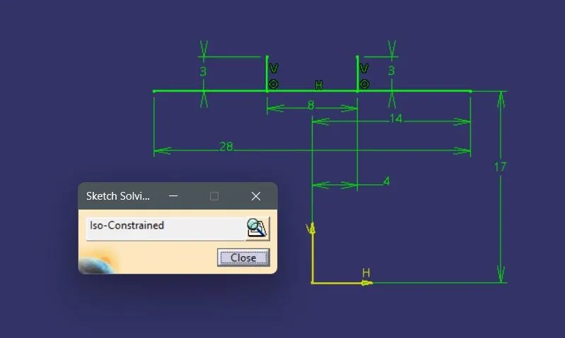
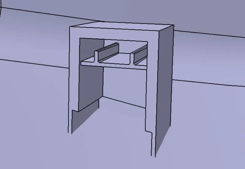
- Step 9: We create another sketch on the previous plane for the cutout.
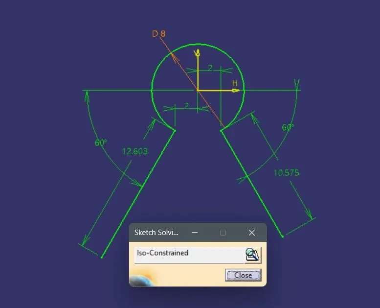
- Step 10: We extrude the sketch and solid snip it from the dog house to get the final dog house. We union trim with the lower substrate to assemble.
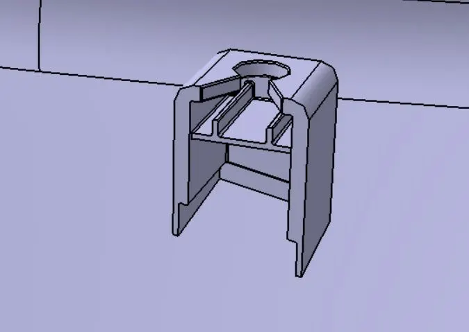
- Step 11: We copy and paste to make duplicates of the above dog house and translate them to all the reference points and do the final union trim with the part body to assemble them.
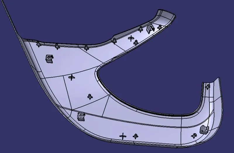
9. Creating the final solid part
- Step 1: We union trim the engineering features to the plain solid part to obtain the final component.
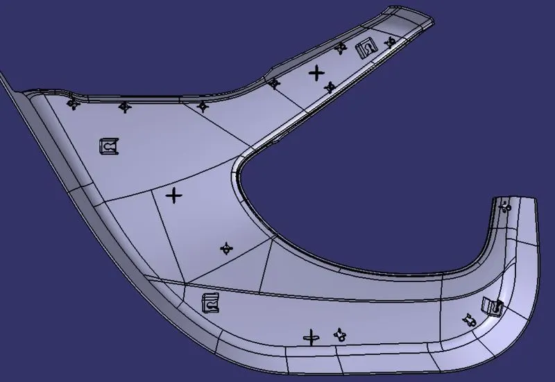
all views
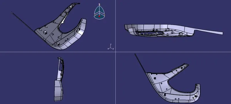
10. Draft analysis
- Step 1: We open the draft analysis command box, select the compass, drag, align it with the tooling axis, and lock it.
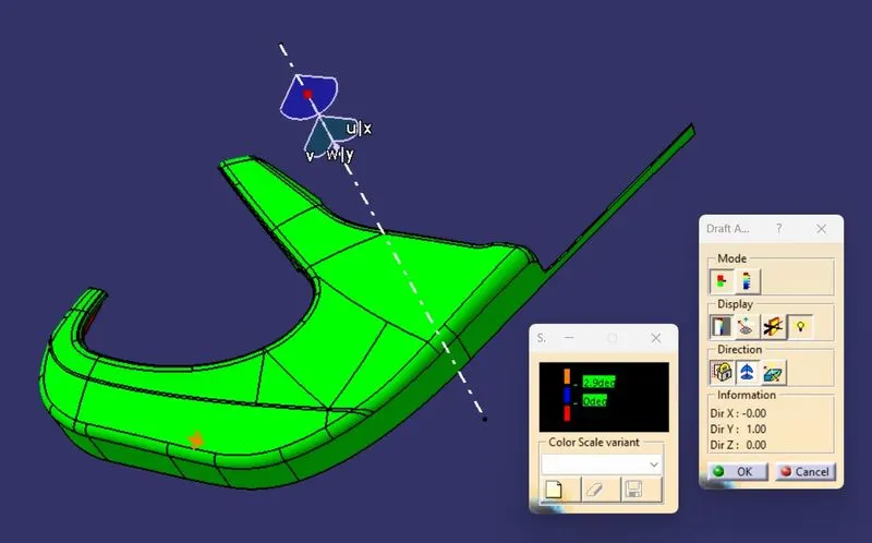
- Step 2: We analyze the color scale, input the required draft value and save the analysis.
DRAFT ANALYSIS
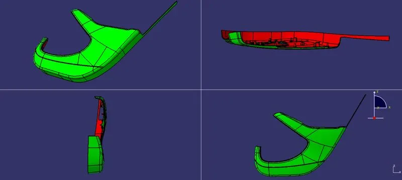
1. For the final plastic component
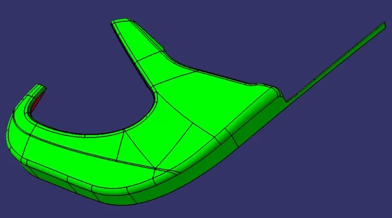
All views
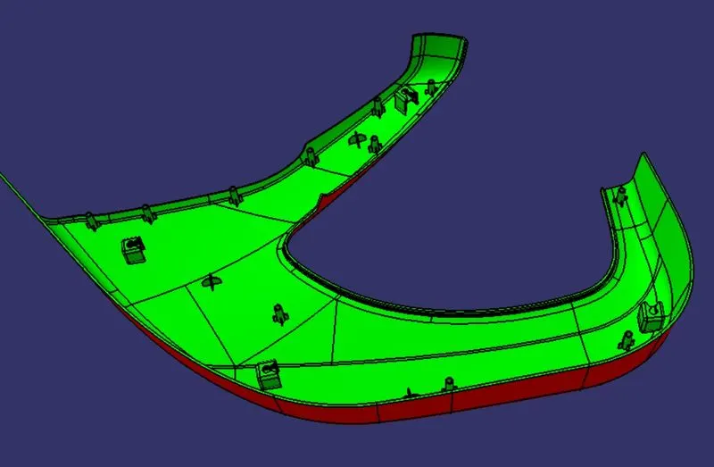
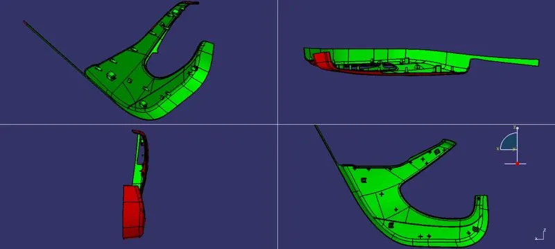
2. For the Engineering features along the main tooling axis
all views
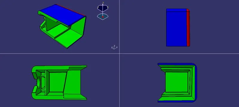
3. For the Dog house along the side core axis
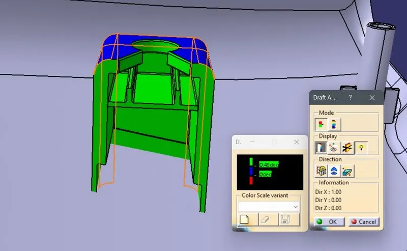
All views
PART 2: ARMREST
1. Defining a Tooling axis for the Class-A surface
- Step 1: Check the connectivity of the surface and ensure there is no gap in the class A surface. The boundary command helps by highlighting the boundary of all the edges thus we can visually check for gaps in the class A surface.
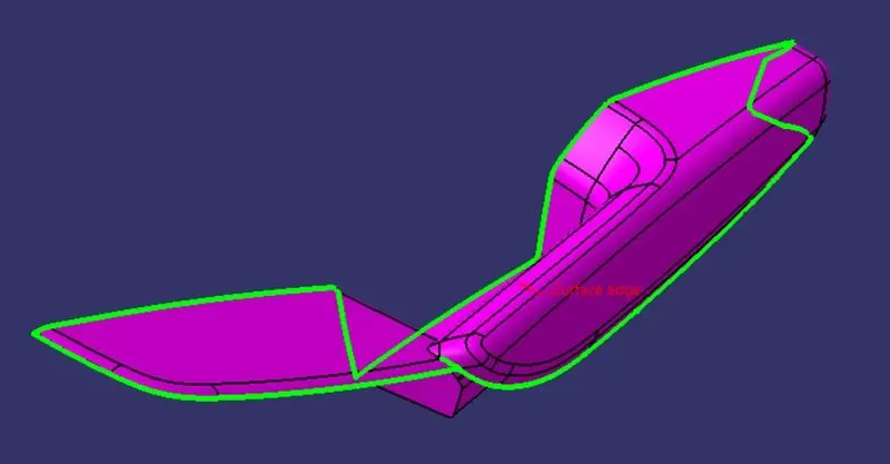
- Step 2: We observe that the class A surface is not perfect so we repair it. We extract the adjacent surfaces and trim them together to remove the irregularity. we also remove the small fillet that might create an error in offset. This is the final class A surface.
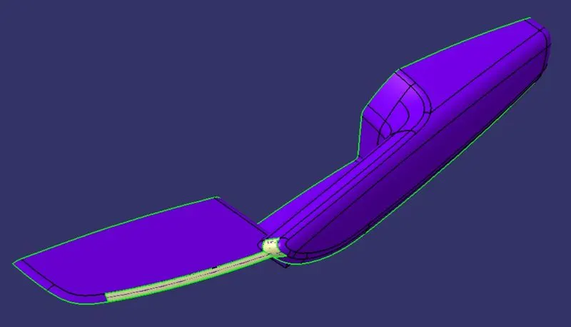
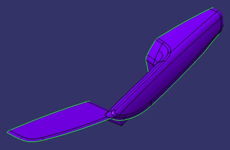
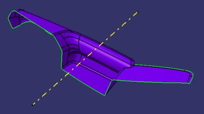
- Step 3: We observe the surface from all three axes to find the optimum tooling axis. Here the Z axis can be the tooling axis.
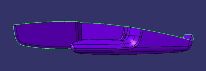
- Step 4: We create a point at the CG of the body and create a line along the Z-axis. This is our main tooling axis.
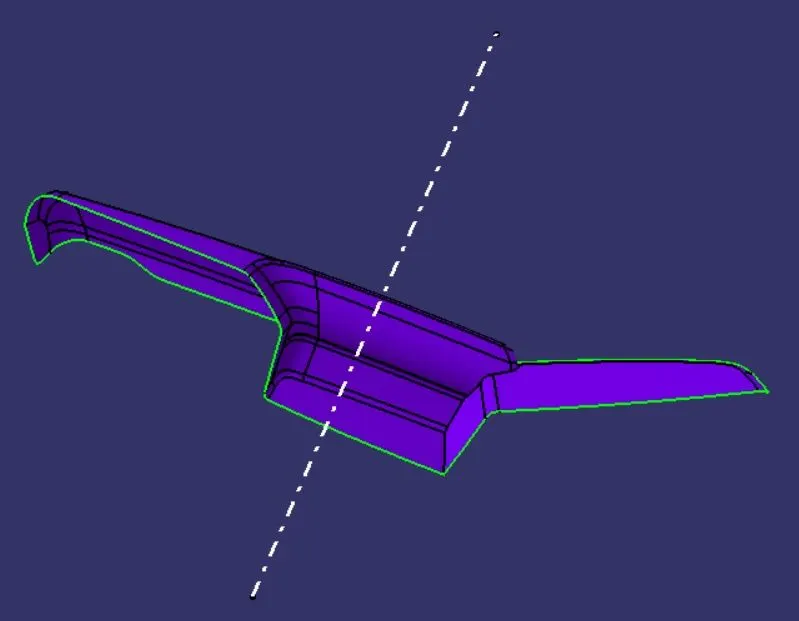
- Step 5: We perform a draft analysis on class A along the main tooling axis to check the feasibility.
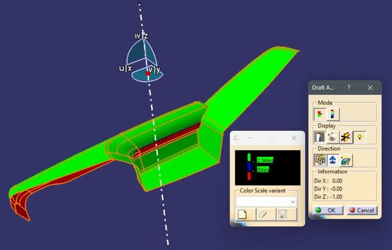
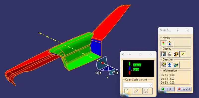
- Step 6: The part can't be cleared along the main tooling axis alone. We need a side tooling axis as well to clear the underside.
- Step 7: We perform a draft analysis on class A along the side tooling axis to check the feasibility.
2. Creating Class B surface
- Step 1: We measure the thickness from the master section which is 2.5 mm.
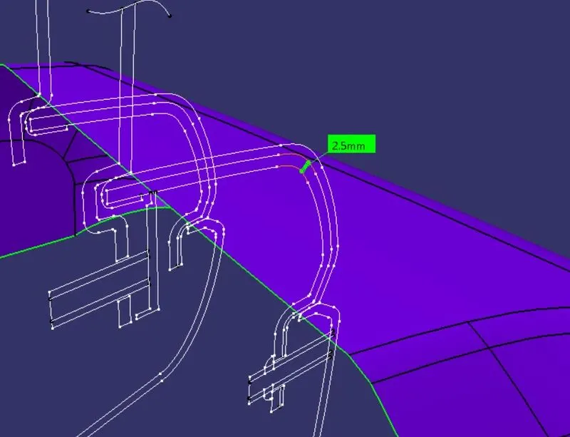
- Step 2:We directly offset the class A for 2.5 mm and observe few discontinuities.
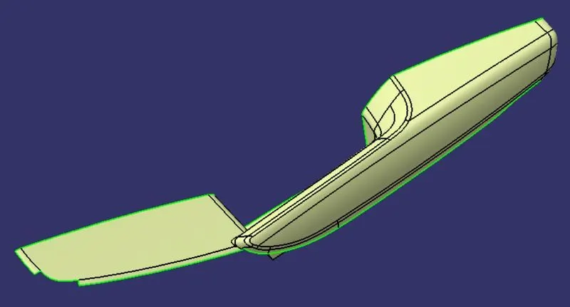
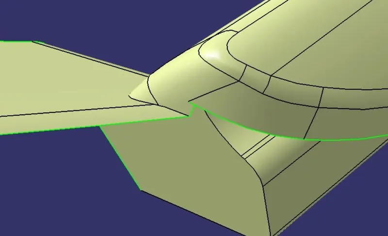
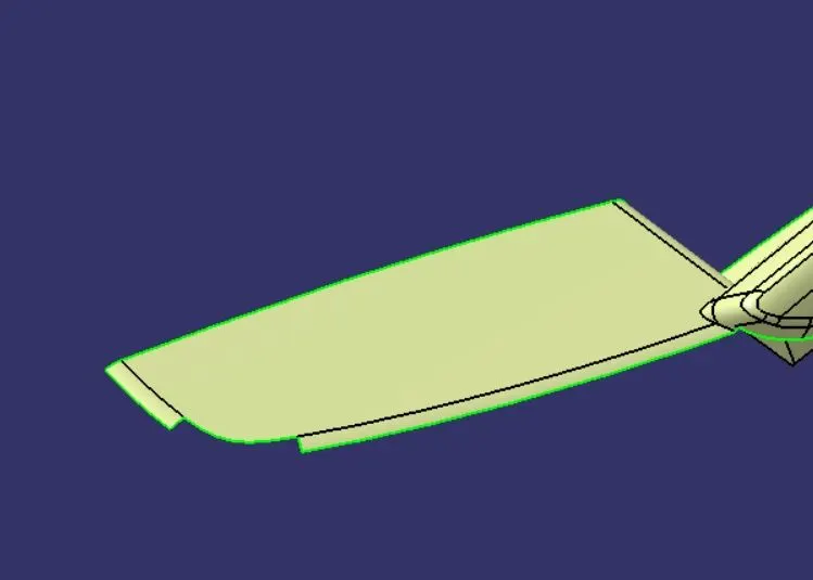
- Step 3: We first repair the end fillet by creating a spline and creating a multisection surface to repair the patch. Then join with the offset.
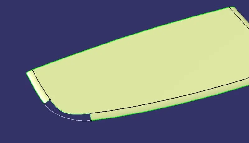
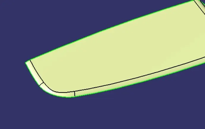
- Step 4: We next repair the joint by extracting the adjacent surfaces and timing them post-extrapolation. We then remove the previous surface and replace it with the trimmed surface.
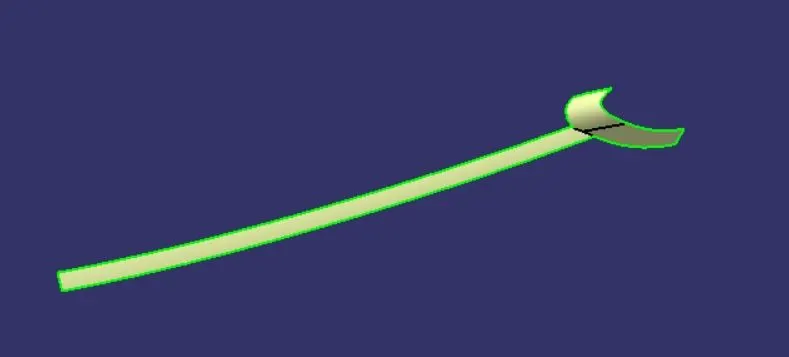
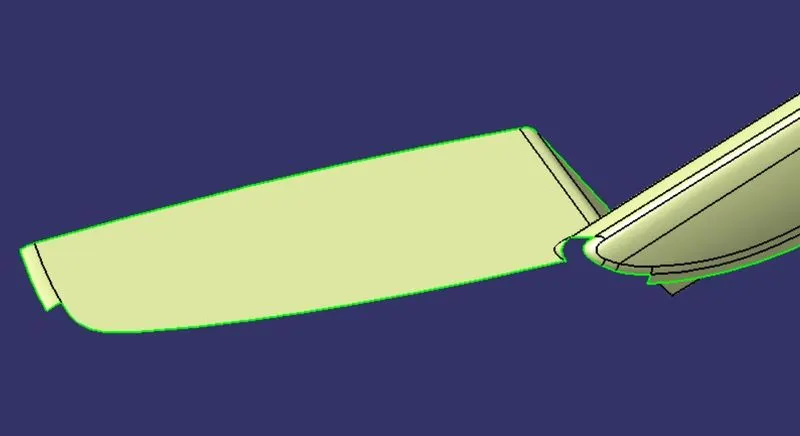
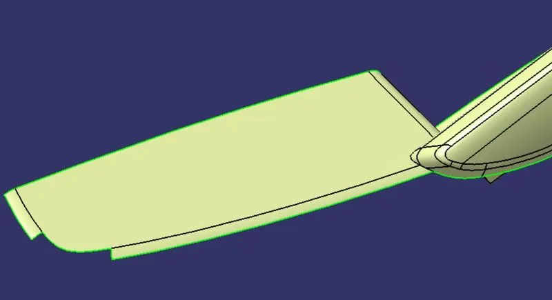
- Step 5: extrapolate the whole boundary for 1.6 mm to get the class B surface.
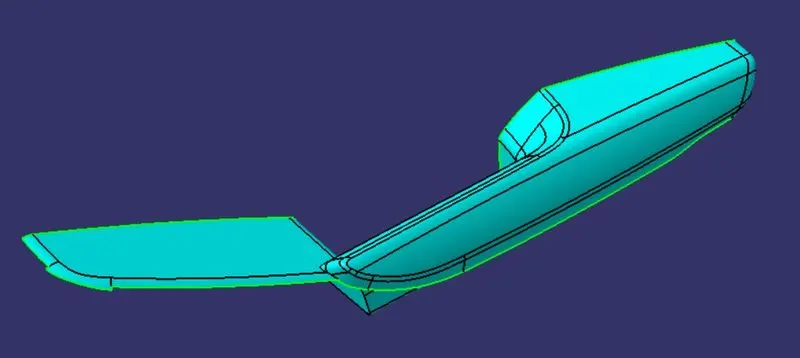
3. Creating Class C surface
- Step 1: We use the boundary command to extract the side edge boundaries into 5 different boundaries.
- Step 2: We sweep with reference surface to create a surface at 90 degrees where it doesn't need clearing for 4mm.
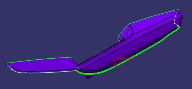
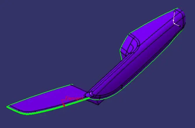
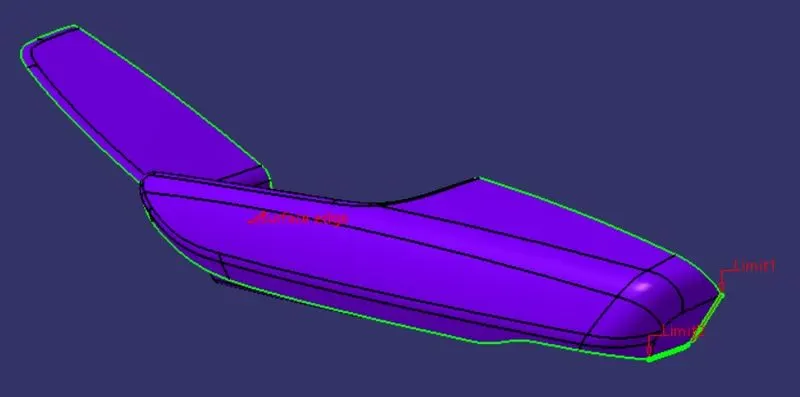
- Step 3: We sweep along with the draft direction as the main tooling axis to create a surface at 3 degrees where it needs clearing for 4mm.
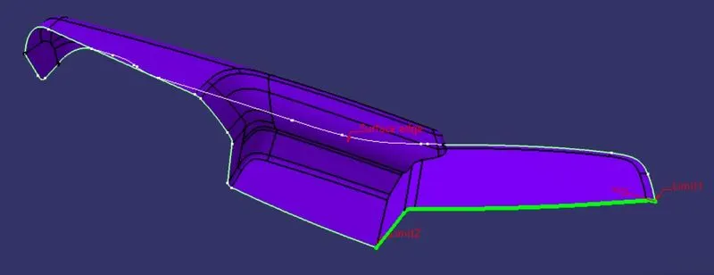
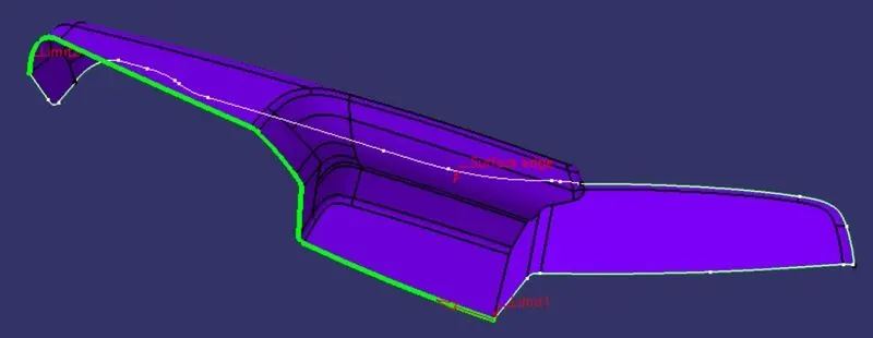
- Step 4: We now create a multisection surface to create surfaces at sharp corners and join with the adjacent sweeps.
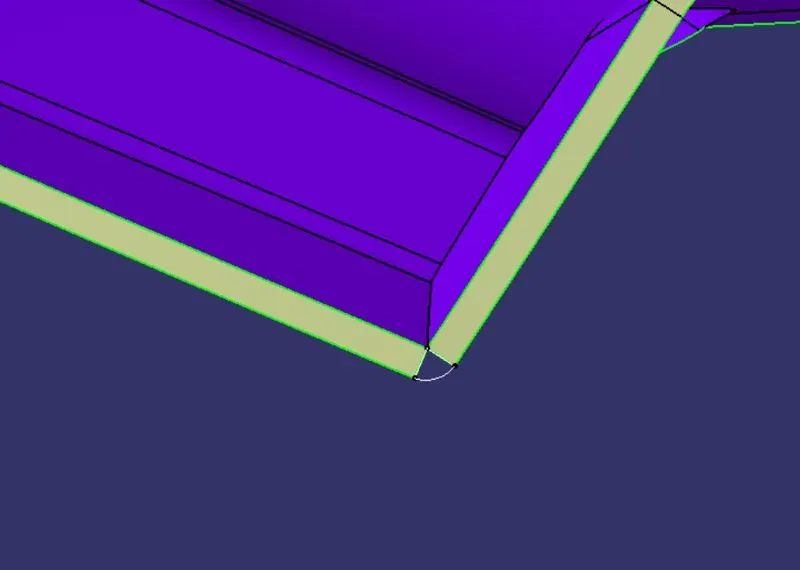
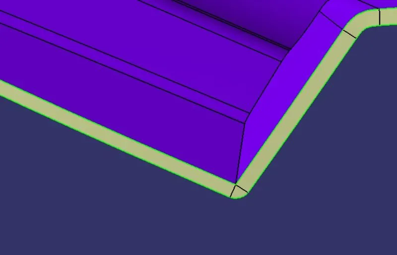
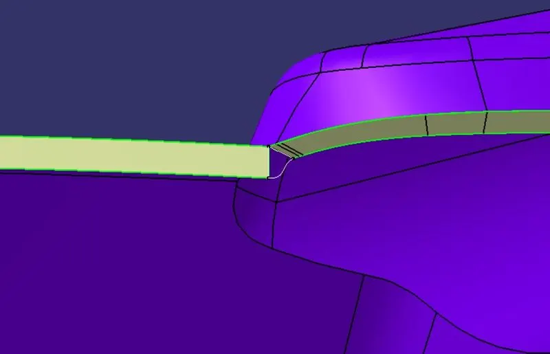
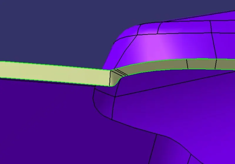
- Step 5: We now extrapolate the ends of the sweep and trim them together to get the final C surface.
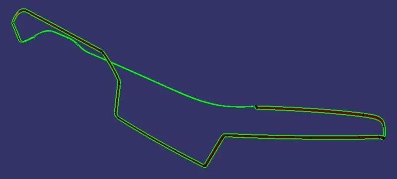
4. Creating the closed volume
- Step 1: We use the join operation to join the Class A, and C surfaces and trim them with Class B surface into one body to get the final surface body.
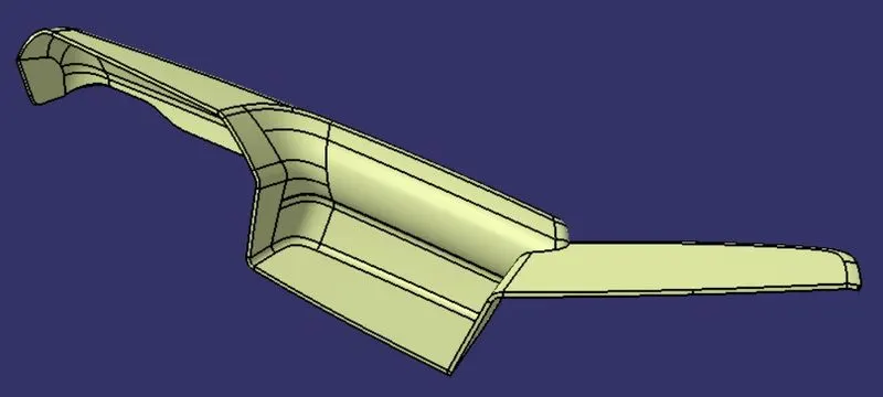
5. Creating the plain solid part
- Step 1: We use the closesurface command in the part workbench to get the solid part.
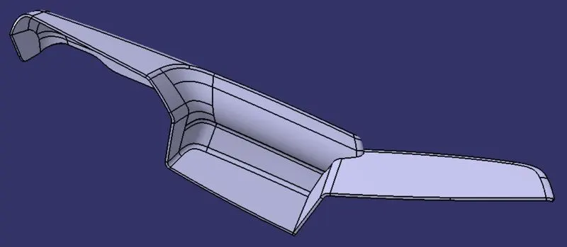
all views
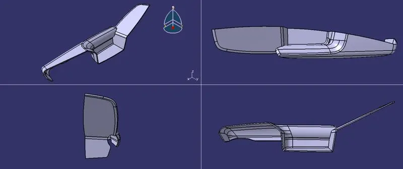
6. Creating the flanges
- Step 1: We create a plane through an isolated midpoint on the master section.
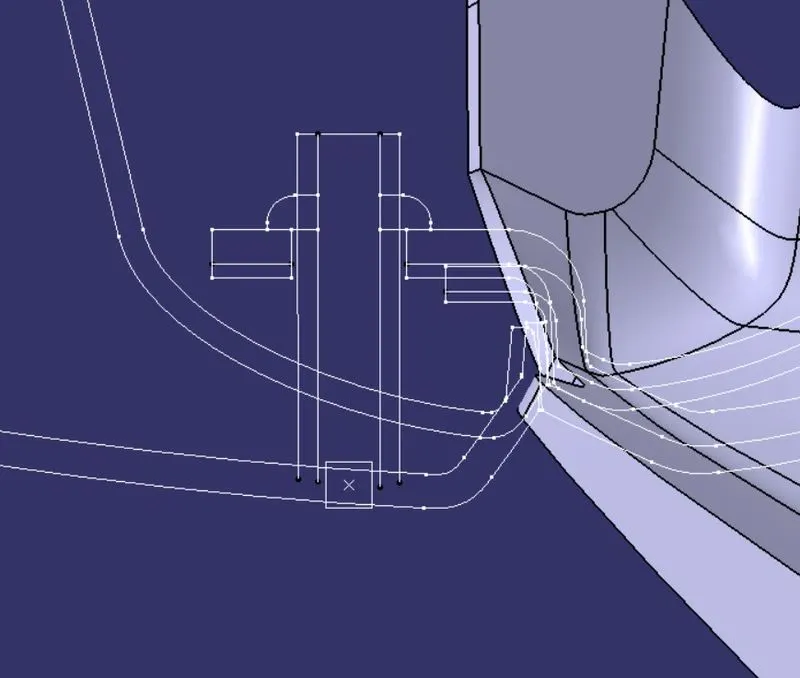
- Step 2: We intersect the plane and the armrest to get the edge. We then create a positioned sketch and project the inside edge of the flange master section and isolate them. we constrain them fully and sweep with the part edge as reference.
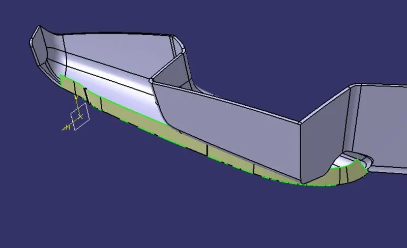
- Step 3: We create a positioned sketch and project the bottom edge of the flange master section and isolate them. we constrain it fully and sweep with the part edge as a reference.
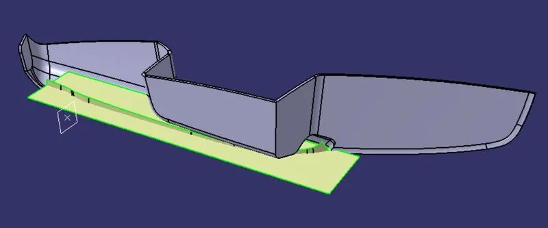
- Step 4: We trim the two sweeps together and thick for 2.5 mm.
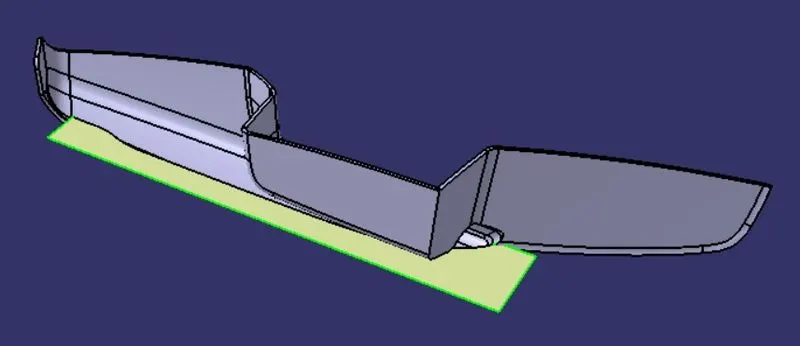
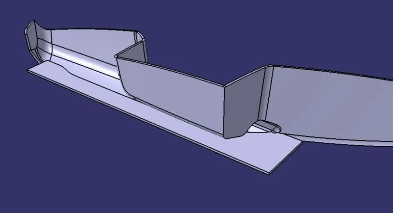
- Step 5: We create planes to snip the flange into the required numbers and positions. We solid snip all the flanges with the heat stake surface offset by 0.5mm and finally draft them to get the final flanges.
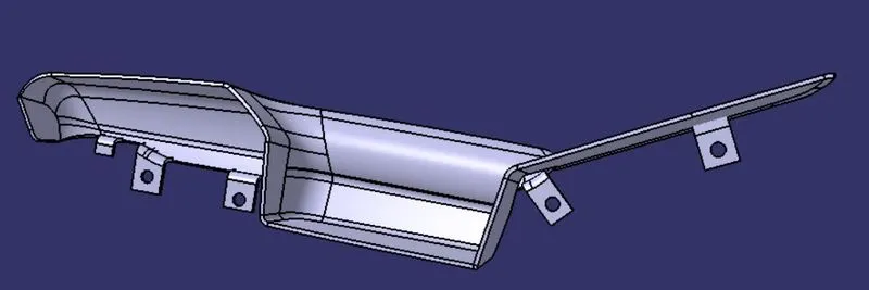
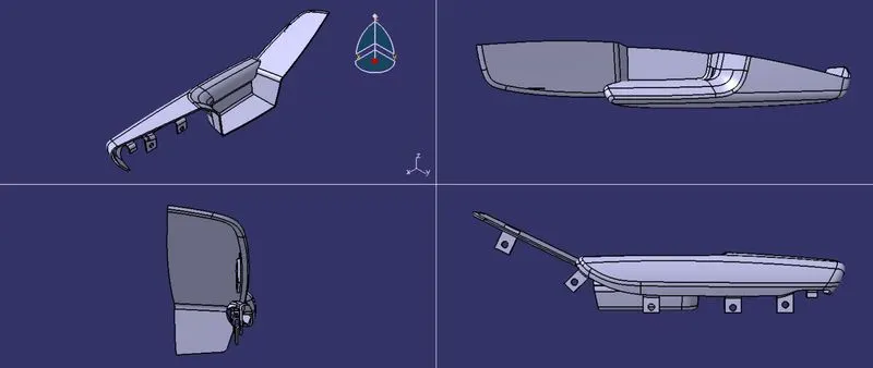
7. Creating the final solid part
- Step 1: We union trim the engineering features to the plain solid part to obtain the final component.
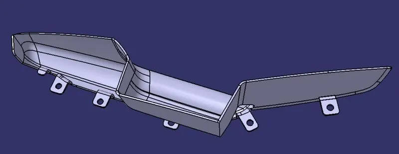
all views
8. Draft analysis
- Step 1: We open the draft analysis command box, select the compass, drag, align it with the main tooling axis, and lock it.
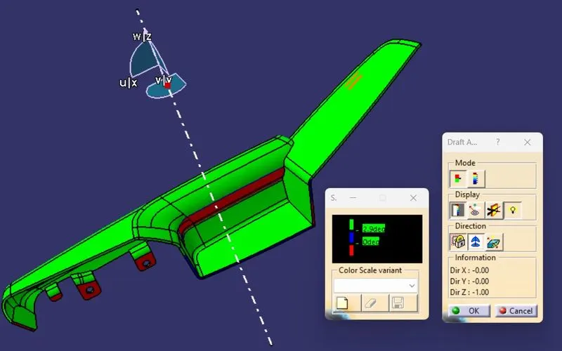
- Step 2: We analyze the color scale, input the required draft value and save the analysis.
DRAFT ANALYSIS
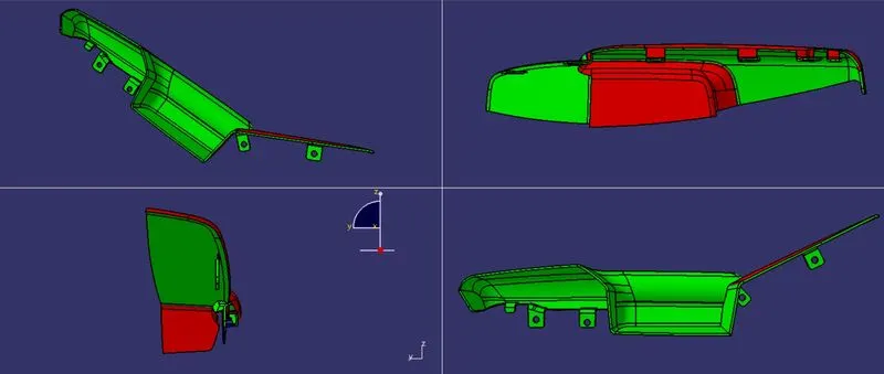
1. For the final plastic component
All views
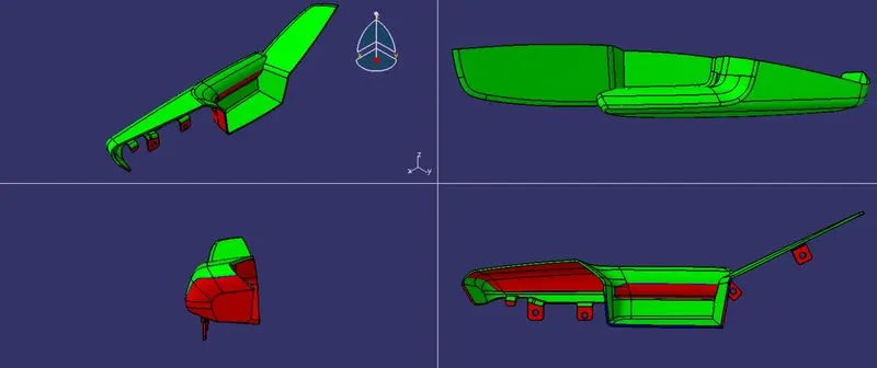
2. For the engineering features along the main tooling axis
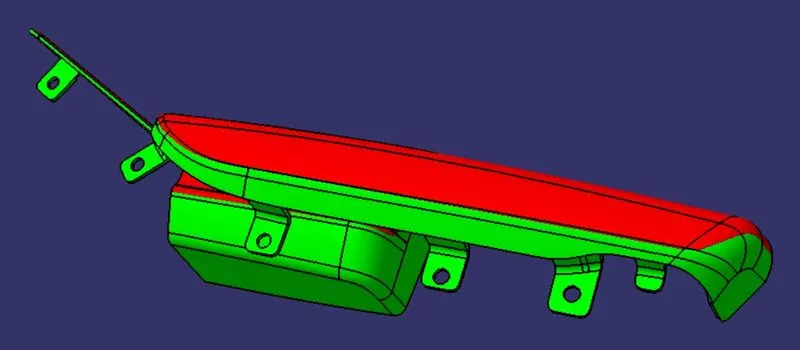
all views
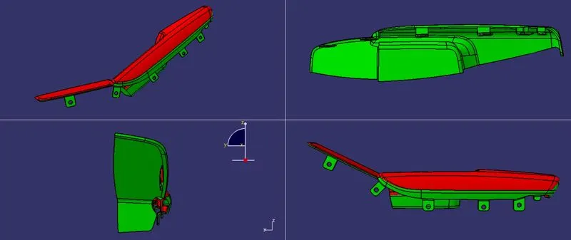
3. For the engineering features along the side core axis
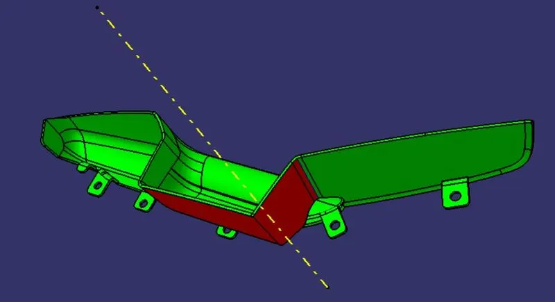
All views
PART 3: MAP POCKET
1. Defining a Tooling axis for the Class-A surface
- Step 1: Check the connectivity of the surface and ensure there is no gap in the class A surface. The boundary command helps by highlighting the boundary of all the edges thus we can visually check for gaps in the class A surface.
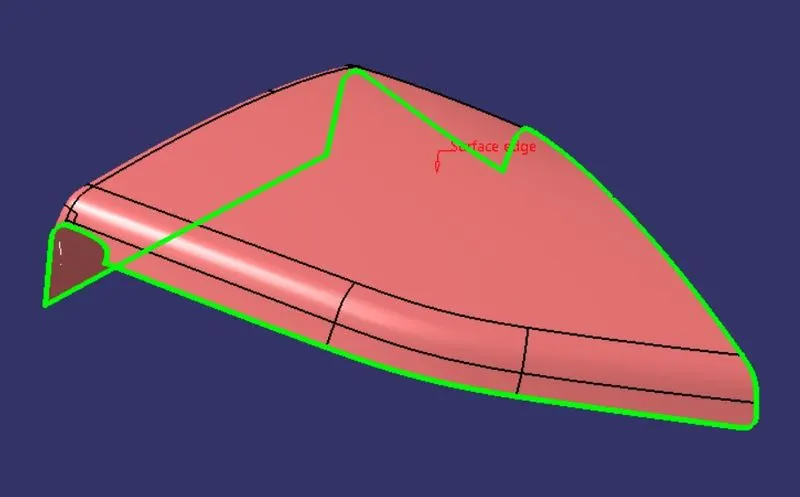
- Step 2: We observe the surface from all three axes to find the optimum tooling axis. Here the Y axis can be the tooling axis.
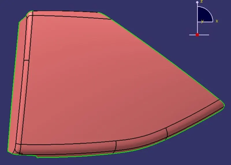
- Step 3: We create a point at the CG of the body and create a line along the Y-axis. This is our main tooling axis.
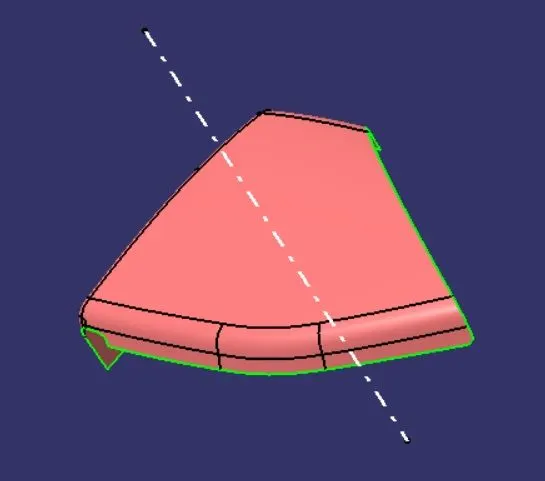
- Step 4: We perform a draft analysis on class A along the main tooling axis to check the feasibility.
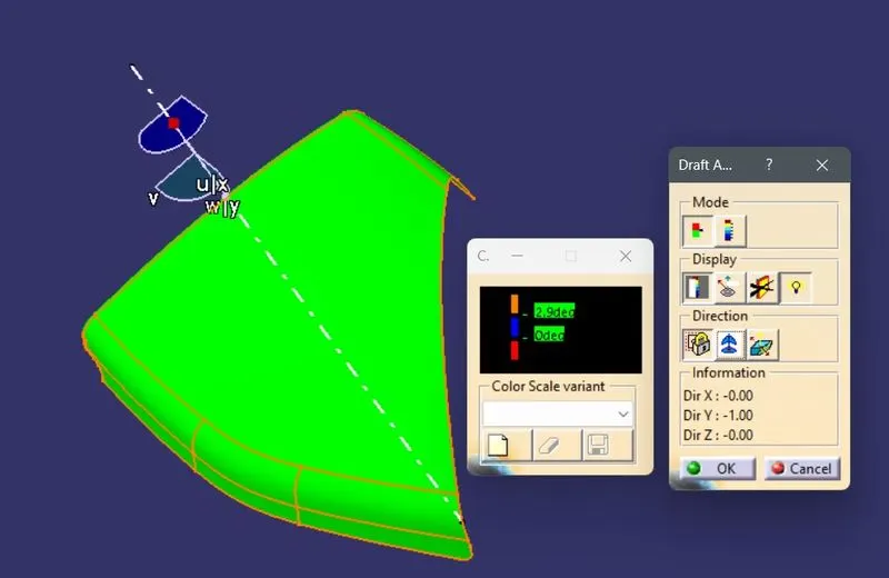
2. Creating Class B surface
- Step 1: We measure the thickness from the master section which is 2.5 mm.
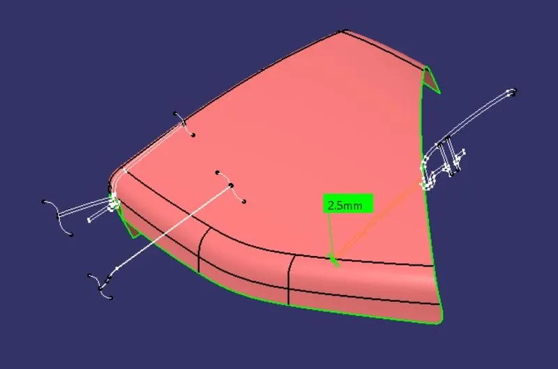
- Step 2:We directly offset the class A for 2.5 mm and observe few discontinuities.
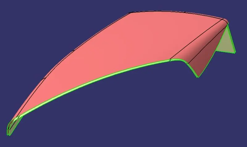
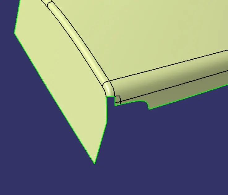
- Step 3: We repair the fillet by creating a multi-section surface by drawing a spline. Then join with the offset.
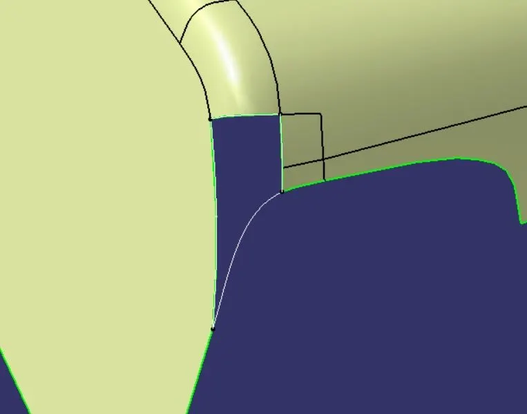
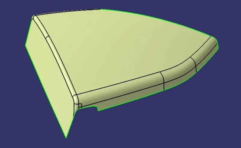
- Step 4: We extrapolate the whole boundary for 2 mm to get the class B surface.
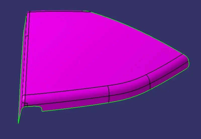
3. Creating Class C surface
- Step 1: We use the boundary command to extract the side edge boundaries into 4 different boundaries.
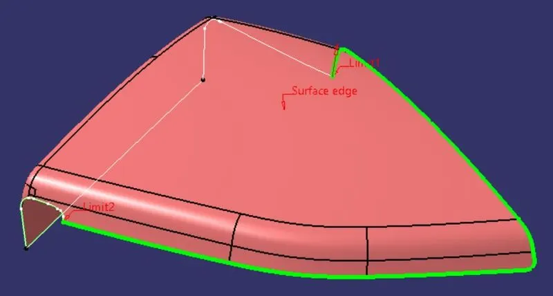
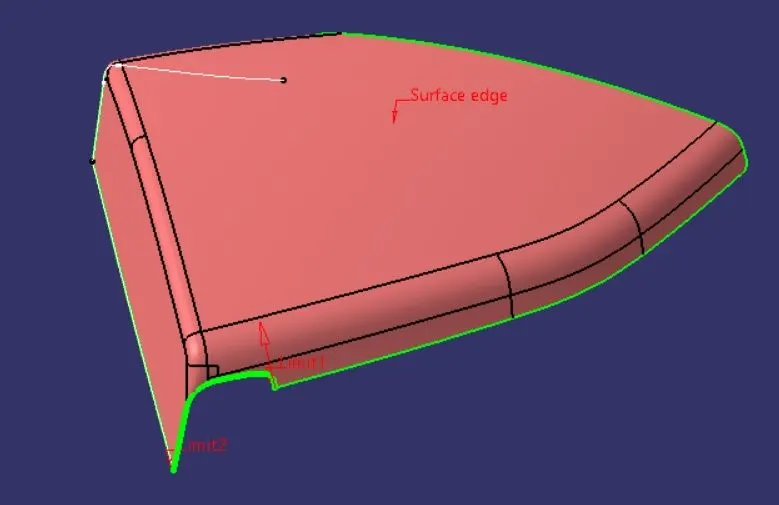
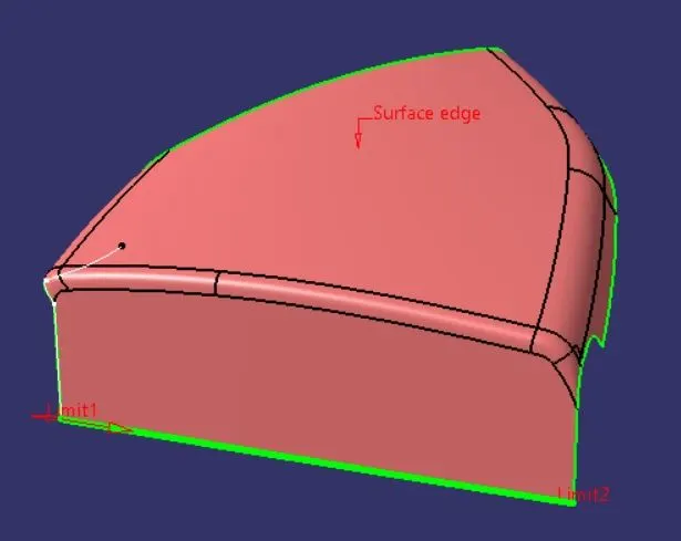
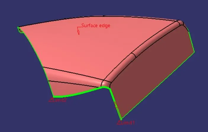
- Step 2: We sweep with reference surface to create a surface at 90 degrees where it doesn't need clearing for 4mm.
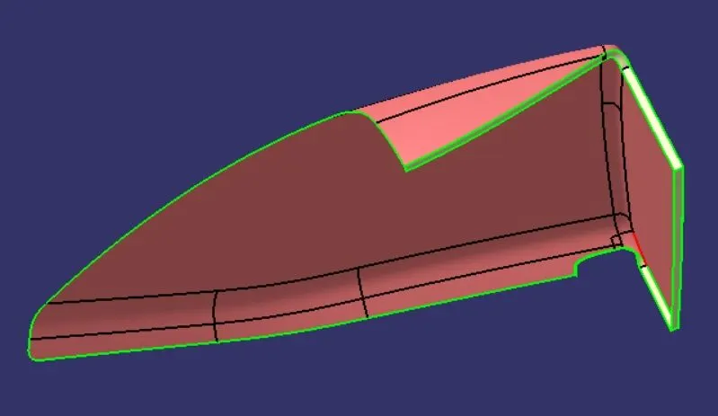
- Step 3: We sweep with reference surface to create a surface at 93 degrees where it needs clearing for 4mm.
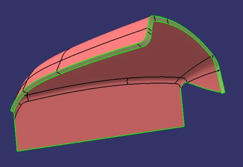
- Step 5: We now extrapolate the ends of the sweep and trim them together to get the final C surface.
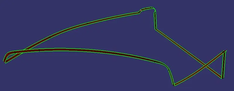
4. Creating the closed volume
- Step 1: We use the join operation to join the Class A, and C surfaces and trim them with Class B surface into one body to get the final surface body.
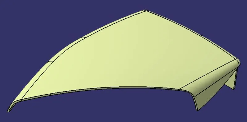
5. Creating the plain solid part
- Step 1: We use the closesurface command in the part workbench to get the solid part.
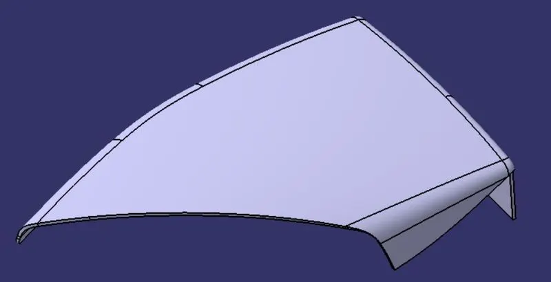
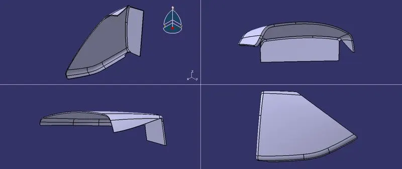
all views
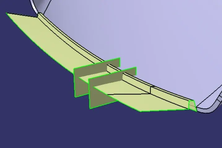
6. Creating the flanges
- Step 1: We create a plane through an isolated midpoint on the master section.
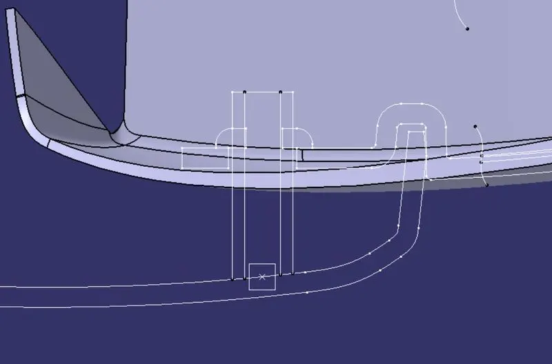
- Step 2: We extract the edge surface and intersect the plane with it to get the edge. We then create a positioned sketch and project the inside edge of the flange master section and isolate them. we constrain them fully and sweep with the part edge as reference.
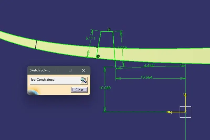
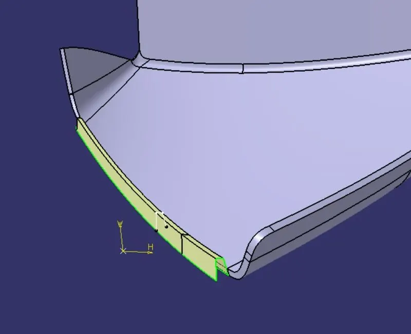
- Step 3: We create a positioned sketch and project the bottom edge of the flange master section and isolate them. we constrain it fully and sweep with the part edge as a reference.
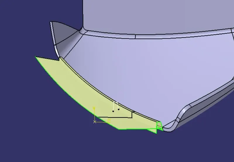
- Step 4: We trim the two sweeps together.
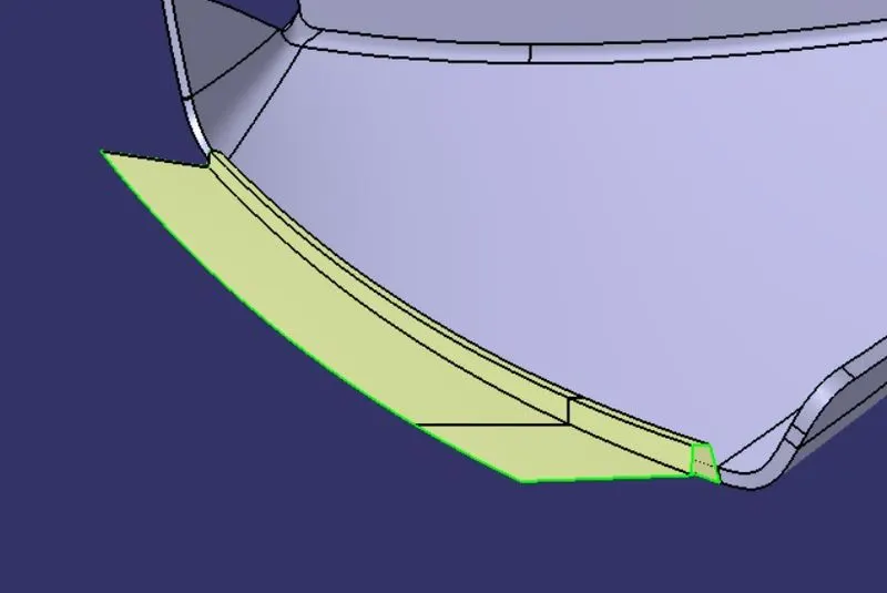
- Step 5: We first create extrudes to surface snip the flange into the required numbers and positions. We then thick each surface for 2.5 mm to get the flange body.
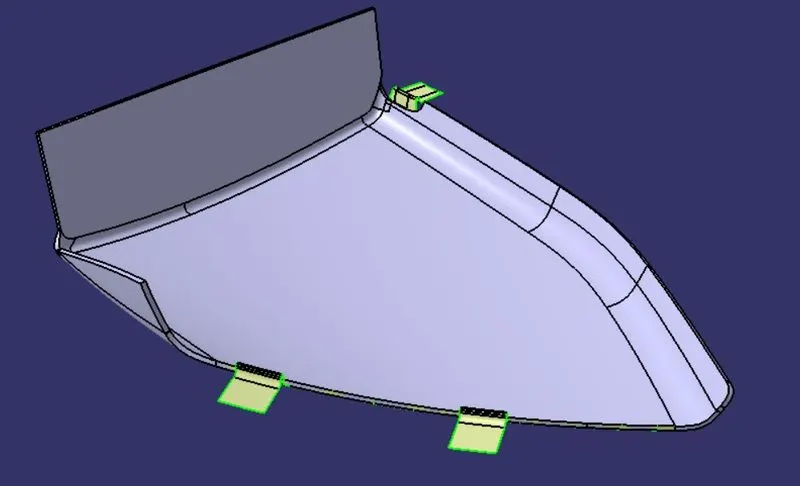
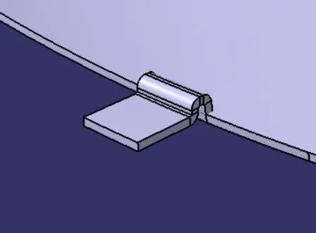
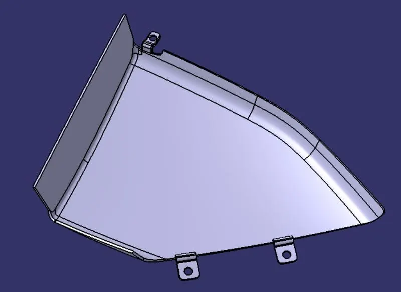
- Step 6: We then solid-snip all the flanges with the heat stake surface offset by 0.5mm and finally draft them to get the final flanges.
7. Creating the final solid part
- Step 1: We union trim the engineering features to the plain solid part to obtain the final component.
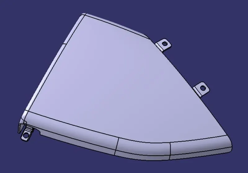
all views
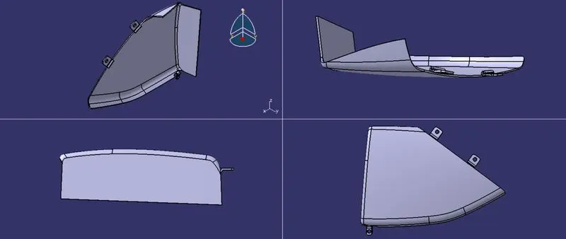
8. Draft analysis
- Step 1: We open the draft analysis command box, select the compass, drag, align it with the main tooling axis, and lock it.
- Step 2: We analyze the color scale, input the required draft value and save the analysis.
DRAFT ANALYSIS
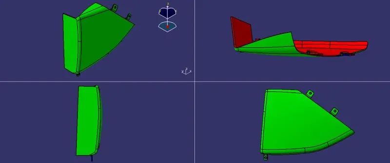
1. For the final plastic component
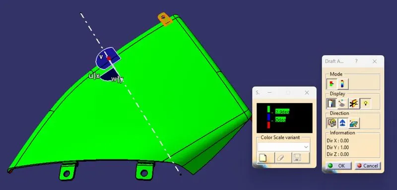
All views
PART 4: BOTTLE HOLDER
1. Defining a Tooling axis for the Class-A surface
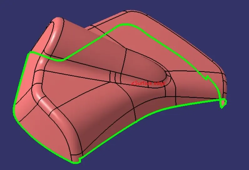
- Step 1: Check the connectivity of the surface and ensure there is no gap in the class A surface. The boundary command helps by highlighting the boundary of all the edges thus we can visually check for gaps in the class A surface.
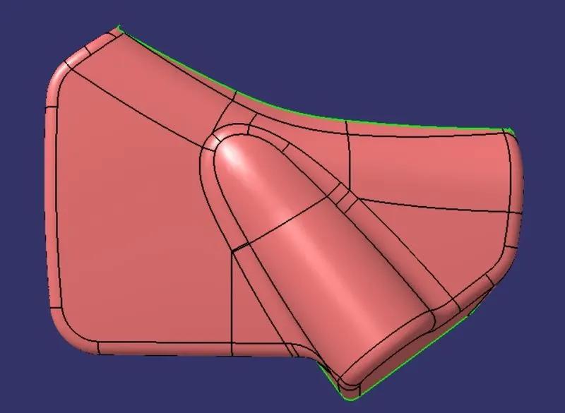
- Step 2: We observe the surface from all three axes to find the optimum tooling axis. Here the Y axis can be the tooling axis.
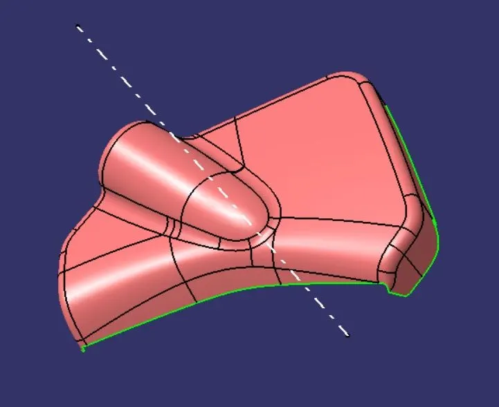
- Step 3: We create a point at the CG of the body and create a line along the Y-axis. This is our main tooling axis.
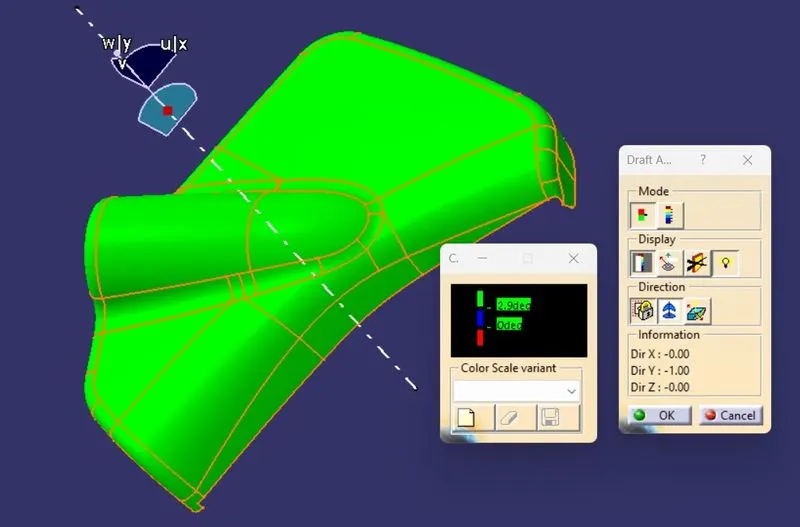
- Step 4: We perform a draft analysis on class A along the main tooling axis to check the feasibility.
2. Creating Class B surface
- Step 1: We offset the Class A surface to 2.5 mm. This is the B surface.
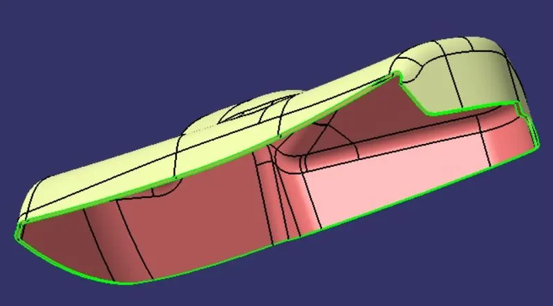
3. Creating Class C surface
- Step 1: We use the boundary command to extract the side edge boundaries into 2 different boundaries and use sweep with reference surface to create a surface at 90 degrees for 4 mm.
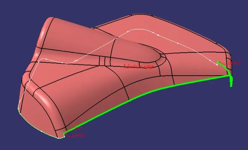
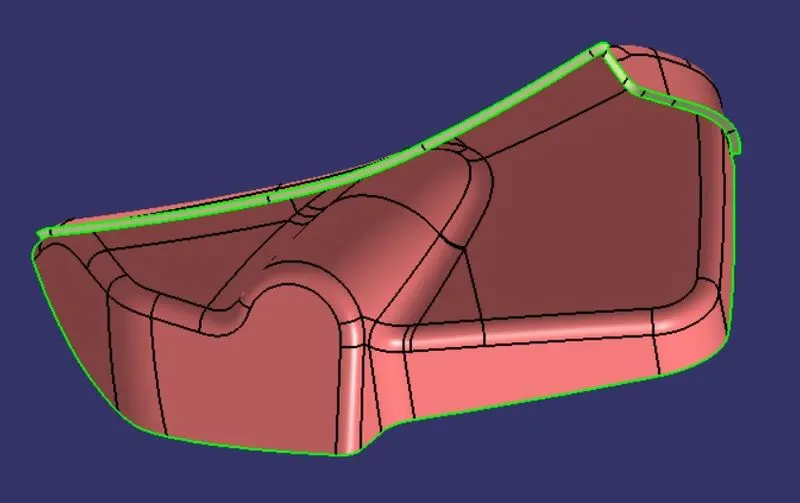
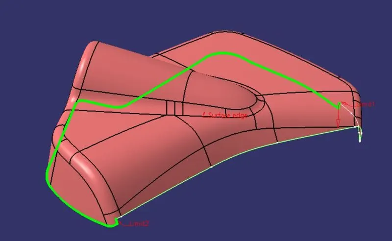
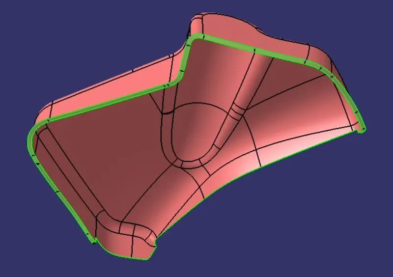
- Step 2: We extrapolate the ends of the above surface and trim both sweeps together to create the final C surface.
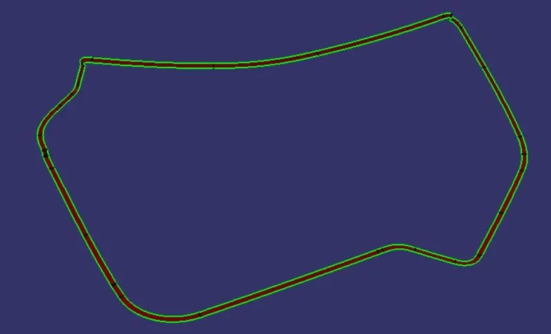
4. Creating the closed volume
- Step 1: We use the join operation to join the Class A, and C surfaces and trim them with Class B surface into one body to get the final surface body.
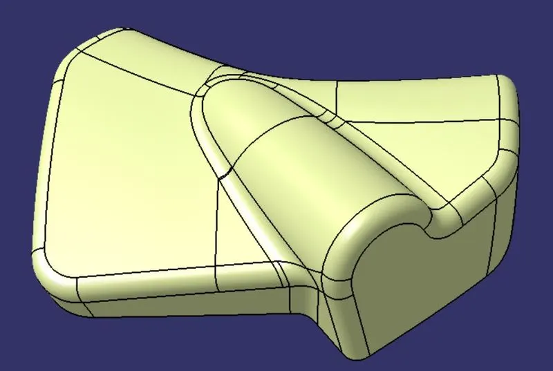
5. Creating the plain solid part
- Step 1: We use the closesurface command in the part workbench to get the solid part.
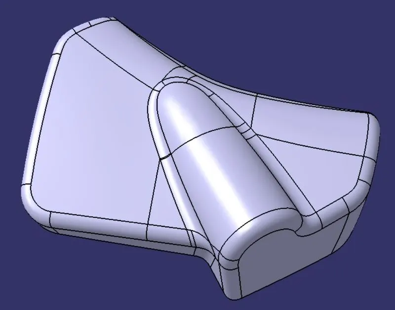
all views
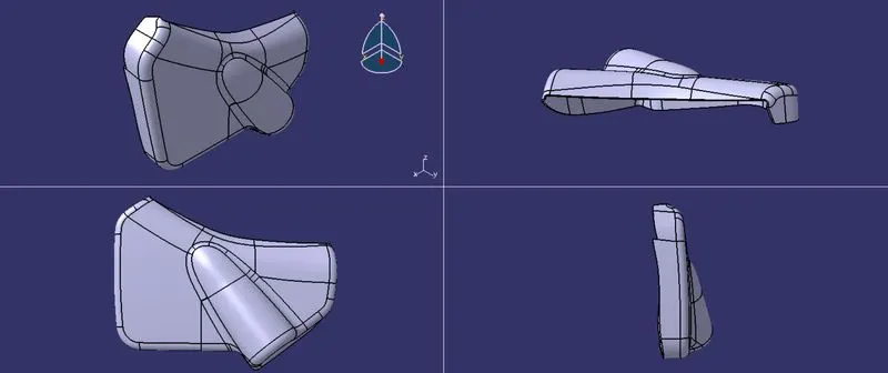
6. Creating the flanges
- Step 1: We create a sketch on the lower substrate heat stake plane and extrude it. Next, we offset it at the required height of the flange. We thicken it for 2.5 mm.
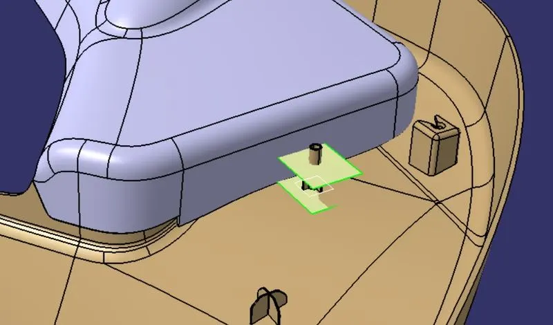
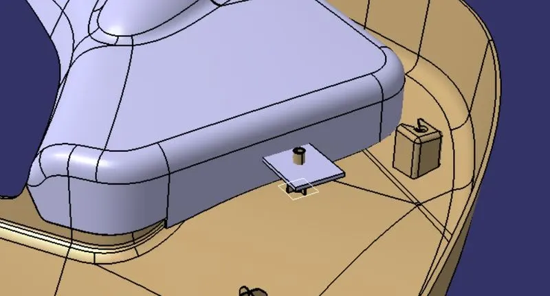
- Step 2: We extrude three surfaces to solid snip the thick surface to shape the flange. We snip the surface.
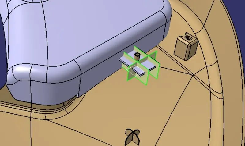

- Step 3: We extract and offset the heat stake surface for 0.5 mm and snip the flange with this.
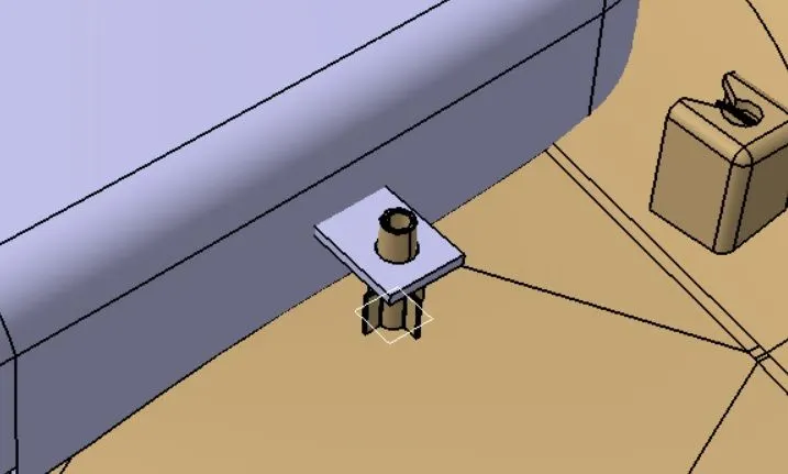
- Step 4: Since the thickness at the joint of the flange and bottle holder might cause sink marks so we must provide coring. We offset the base flange surface for 1 mm and the extract of the part surface for 3 -6 mm and trim them together to get the coring surface.
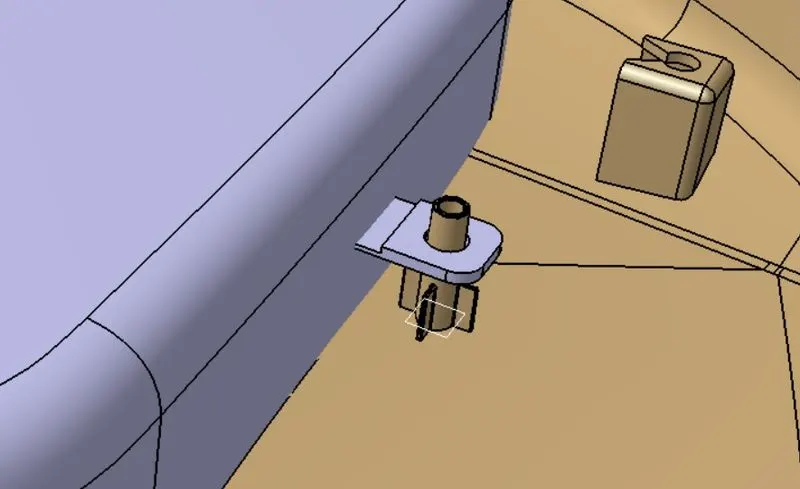
- Step 5: We then solid-snip the flange with the coring surface to get the final flange. We similarly create flanges at the other heat stake locations.
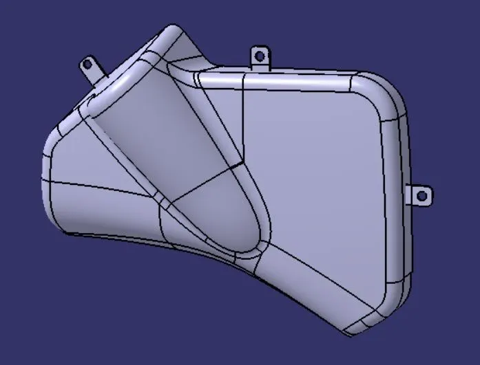
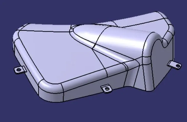
7. Creating the final solid part
- Step 1: We union trim the engineering features to the plain solid part to obtain the final component.
all views
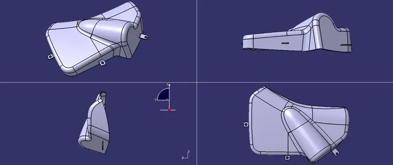
8. Draft analysis
- Step 1: We open the draft analysis command box, select the compass, drag, align it with the tooling axis, and lock it.
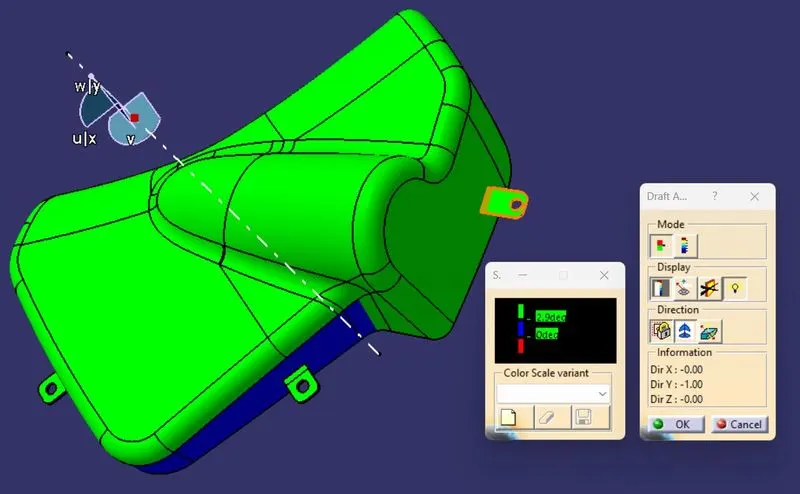
- Step 2: We analyze the color scale, input the required draft value and save the analysis.
DRAFT ANALYSIS
1. For the final plastic component
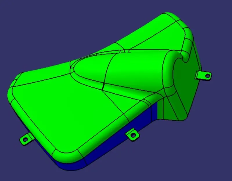
All views
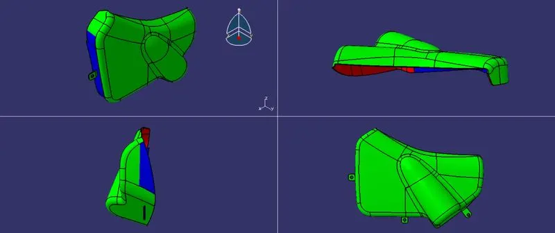
FINAL ASSEMBLY OF DOOR TRIM
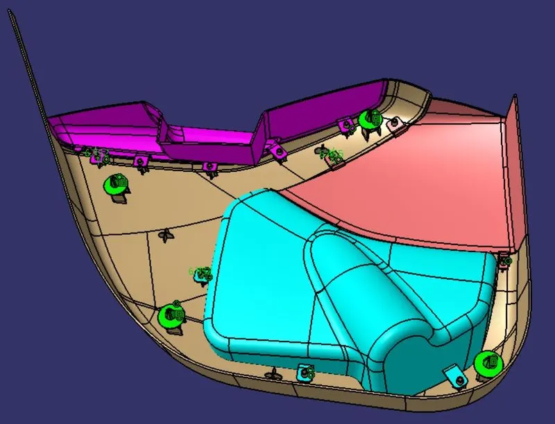
- Step 1: We first input 4 Push Pin Clip bodies.
- Step 2: We fix the lower substrate. We also create reference axes for all heat stakes and dog house pin slots.
- Step 3: We also create reference axes of flange holes for all individual parts.
- Step 4: We also create reference axes for push-pin clips.
- Step 5: We then use coincidence constraint to coincide the axes of parts and pish pins with the lower substrate.
- Step 6: We also use contact constraints to fix the push pins and offset constraints to fix the armrest, map pocket, and bottleholder.
- all views