Week 11 - Final project
INPUT OF CLASS A SURFACE:
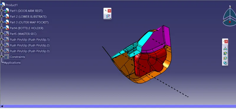
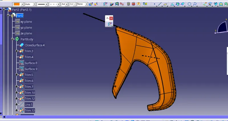
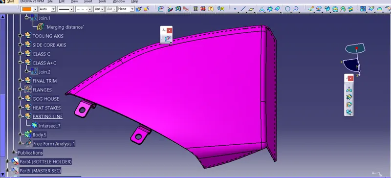
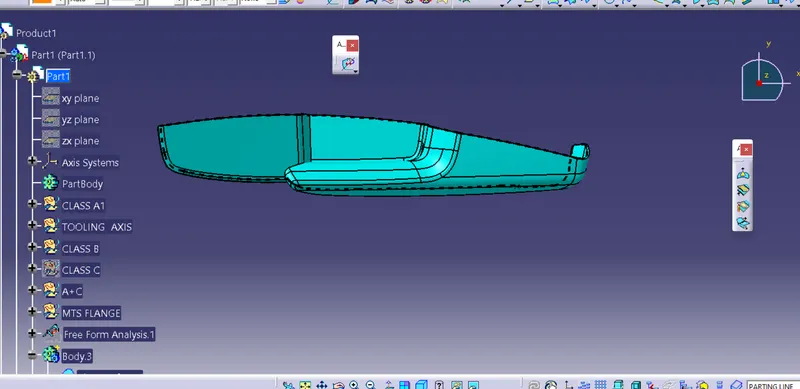
I iport the all class A sufaces. , A surface is containing four different parts(class A). So class b and c for all the surface has been created in separate catpart. Also performing draft analysis and tooling axis separately. finally, all surfaces have assembled together and finally make it one cat product.
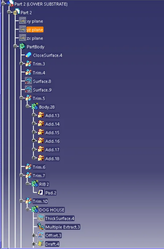
CREATION OF TOOLING AXIS — LOWER SUBSTRATE
DRAFT ANALYSIS
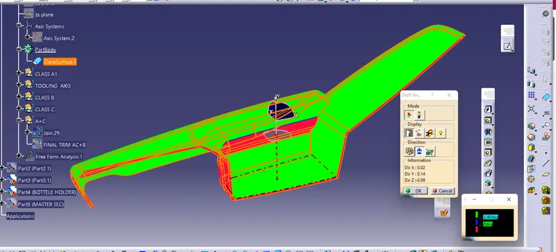
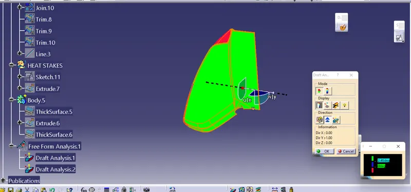
Draft analysis in CATIA is a command that is used to find the your part is easily removed from mold or not . it is performed based on color ranges identifying zones on the analyzed element.
Most of the industries is using a minimum draft angle is 3 degrees.
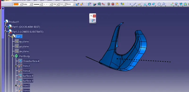
PROCEDURE:
- Check all the boundaries whether it has connected or not.
- Check the model visually & choose the best tooling direction which should be easy to draft.
- Create a point- Direction line parallel to the Y direction as shown above.
- The line is named tooling Axis.
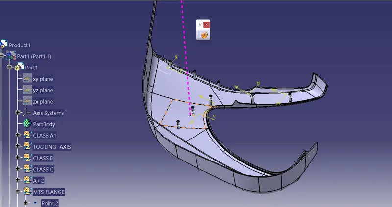
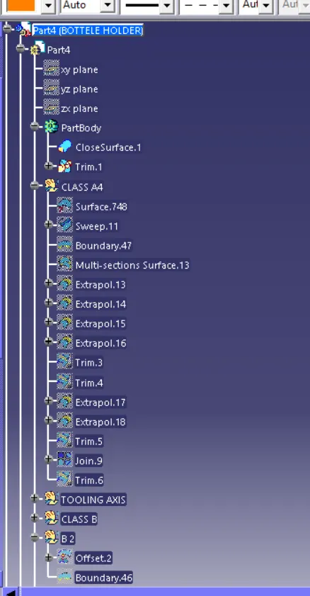
CREATION OF TOOLING AXIS — BOTTLE HOLDER
PROCEDURE:
- Check all the boundary whether it has connected or not
- Check the model visually & choose the best tooling direction which should be easy to draft.
- After analyzing the above model, we have to create a tooling axis on Y.
CREATING THE TOOLING AXIS:
- Here i extract the suitable surface for create the point .
- Created a point by co-ordinate method.
- then ctreated a tooling axis by point and direction method (Y direction) as shown in the belove.
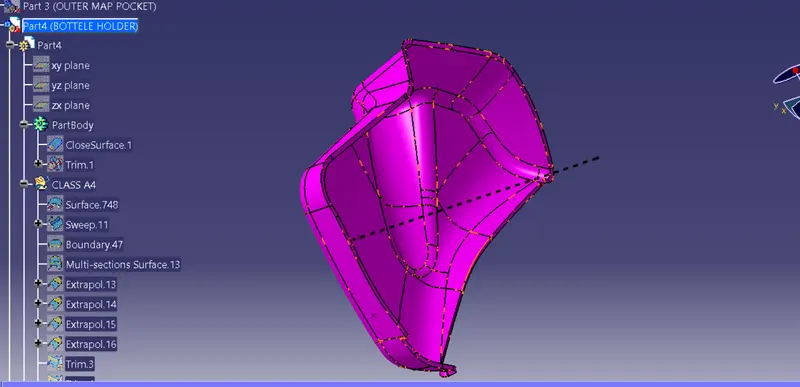
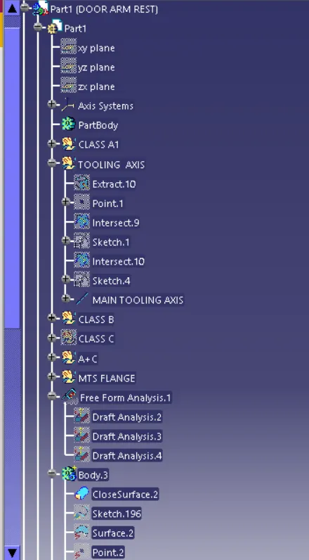
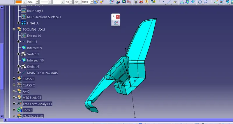
CREATION OF TOOLING AXIS — DOOR ARMREST
PROCEDURE:
- Check all the boundary whether it has connected or not
- Check the model visually & choose the best tooling direction which should be easy to draft.
- Then we have to create a tooling axis in the Y direction.
CREATING THE TOOLING AXIS:
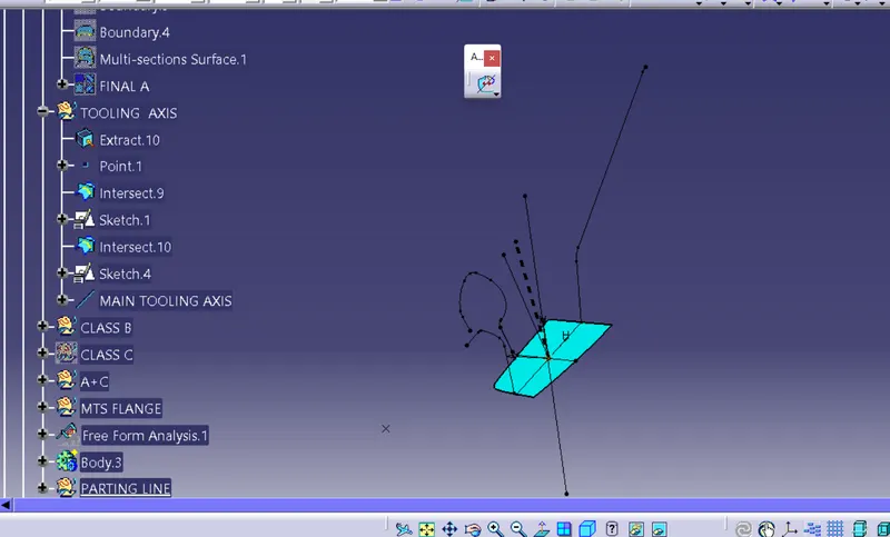
- Create a point and insert an axis system on point one as shown below.
- create an intersection on the ZY plane for the given surface
- create a point to point line as shown below
- add a bisecting line as shown below by the reference of two lines created below named as Tooling facing Z direction
- Creating an intersection on the ZX plane for the given surface.
- Add a bisecting line as shown above and named as Tooling facing z-direction.
- Add bisecting by the reference of tooling Facing X direction and y direction and named as tooling axis.
As per the point and direction method i usd for all surfaaces for creat the tooling axis as shown in below.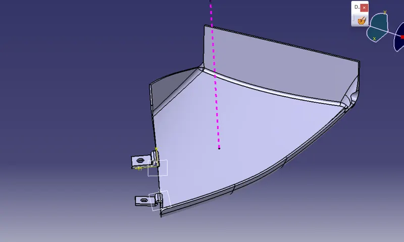
Drafting analysis on the Class A surface:
- After creating the solid body we will perform the draft analysis of the whole part body.
- Check the draft if it is correct or not by using draft analysis tool.
- Click on the compass icon & align with the tooling axis.
DRAFTING ANALYSIS REPORT OF CLASS A SURFACE - DOOR ARM REST.
DRAFTING ANALYSIS REPORT OF CLASS A SURFACE - LOWER SUBSTRATE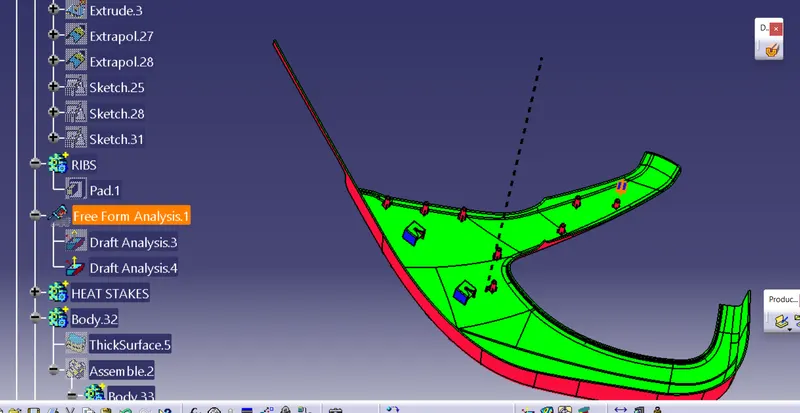
DRAFTING ANALYSIS REPORT OF CLASS A SURFACE - BOTTLE HOLDER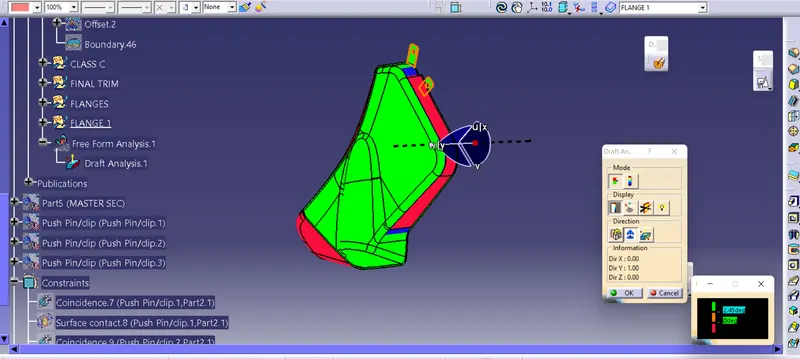
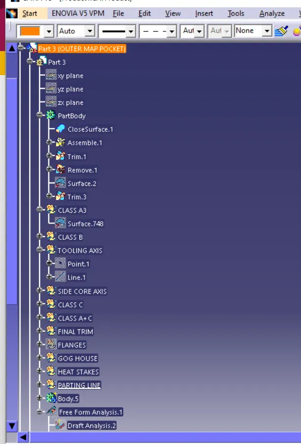
DRAFTING ANALYSIS REPORT OF CLASS A SURFACE - SMAP POCKET
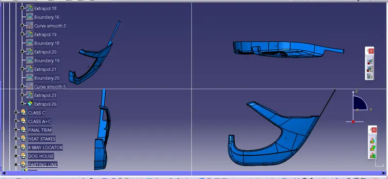
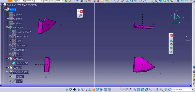
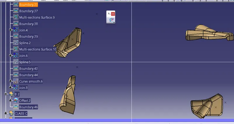
CREATION OF CLASS B SURFACE OF ALL SURFACES:
- Insert a new geometrical set to measure the value of thickness in the master section. the value is 2.5mm.
- offset the class A surface to 2.5mm
- check all the elements are formed if not we have to recreate them.
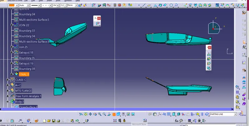
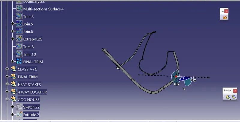
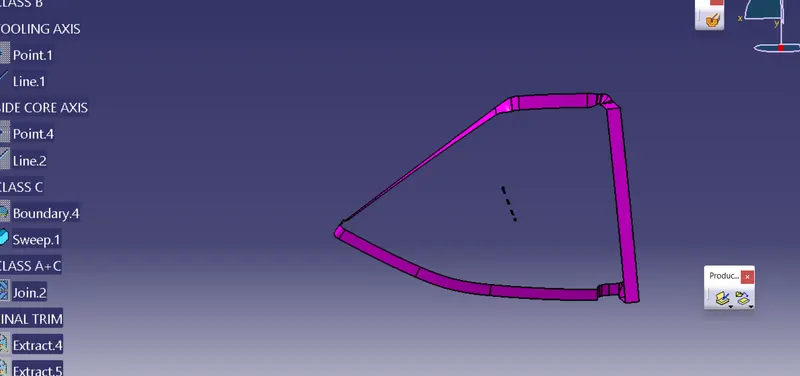
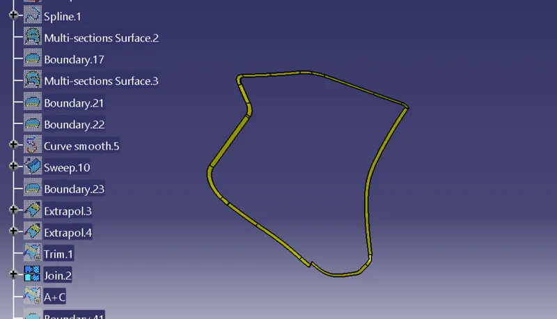
CREATION OF CLASS C SURFACES FOR ALL CLASS A SURFACES :
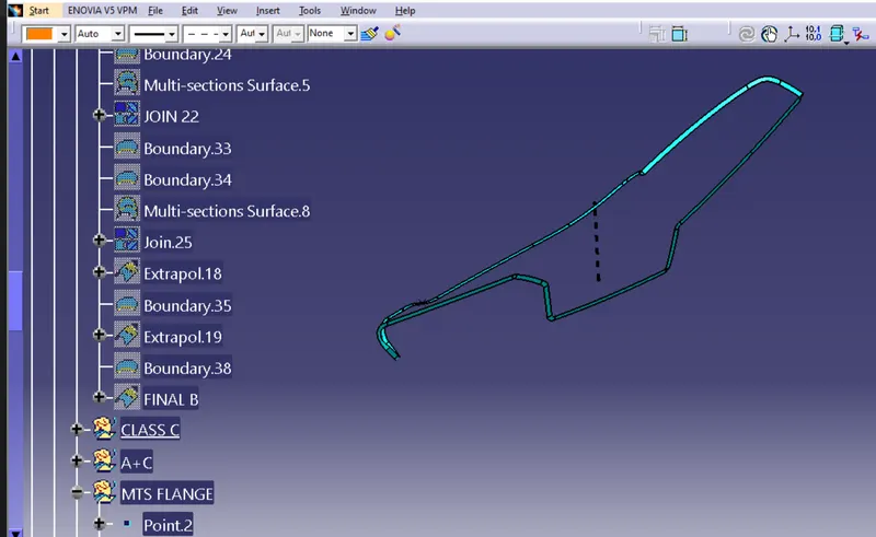
- Analysis the class A once where the sweep is easier to create towards tooling direction
- create a boundary using the limitation points wherever possible for a sweep.
- Sweep the above boundaries for industrial standard 3 degrees towards Tooling Axis.
- Now create the C surface by using multisection solid wherever the sweep cant perform.
- Create a boundary using a Class A surface that is going to perform a multisection surface.
- now trim the surface with class B to form a closed surface.
CREATION OF B SIDE ATTACHMENT FEATURES:
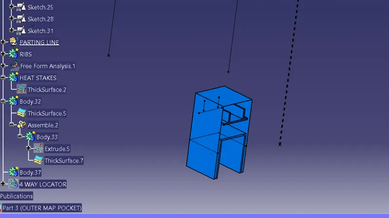
DOG HOUSE
- Extract the surface that we going to create a dog house
- insert axis system use the positioned sketch and draw a dog house sketch.
- pad the sketch for the required length.
-
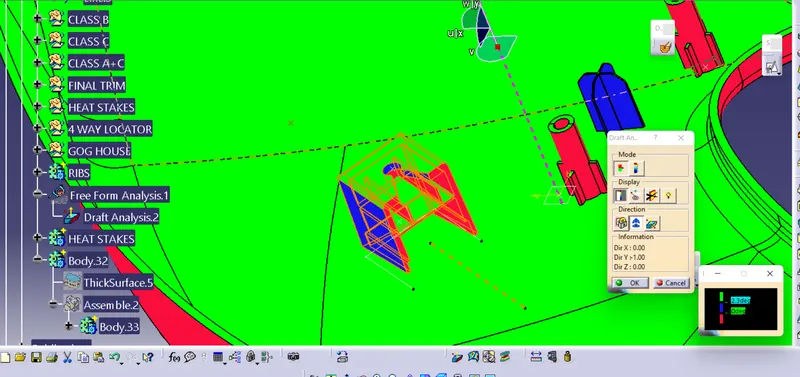
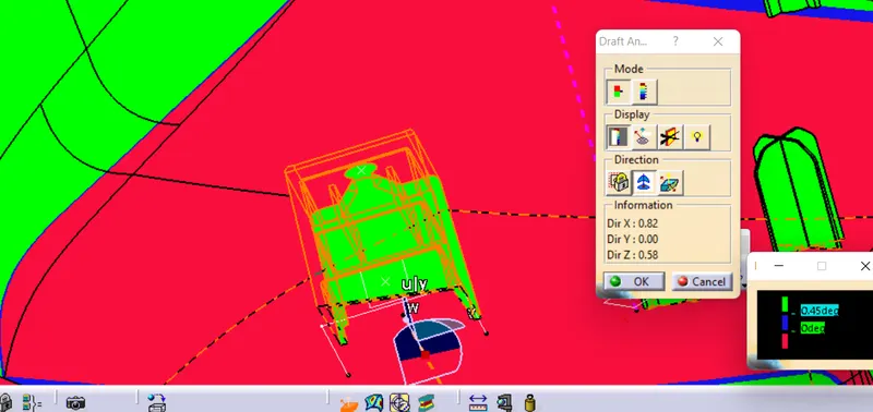
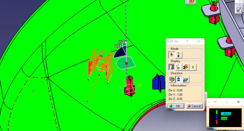
Use Drafting commend to create an angle degree of 3 along the tooling axis as a direction.
- Finally create the dog house on lower substrate and samp pocekt.
- Then perform the draft analysis along with main tooling axis and side core axis.
- The draft angle inside the dog house is 0.5°(0.45 with side core axis) and out side 3(2.45 with main tooling axis).
HEAT STAKES:
Heat stakes are used for the process of joining two dissimilar metals together.
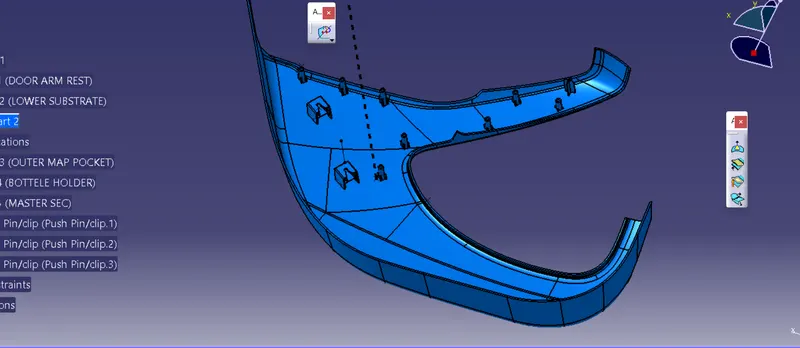
- Extract the surface that we are going to create Heat stake.
- use positioned sketches and draw a heat stakes sketch.
- use extrude commands for creat surface of heat stakes and tuse thicksurface command for create solid heat stake body
- draft the stakes minimum of 0.5 Degree.
- add fillet 0.25mm to all faces.
- Assemble the heat stakes to lower substrate solid.
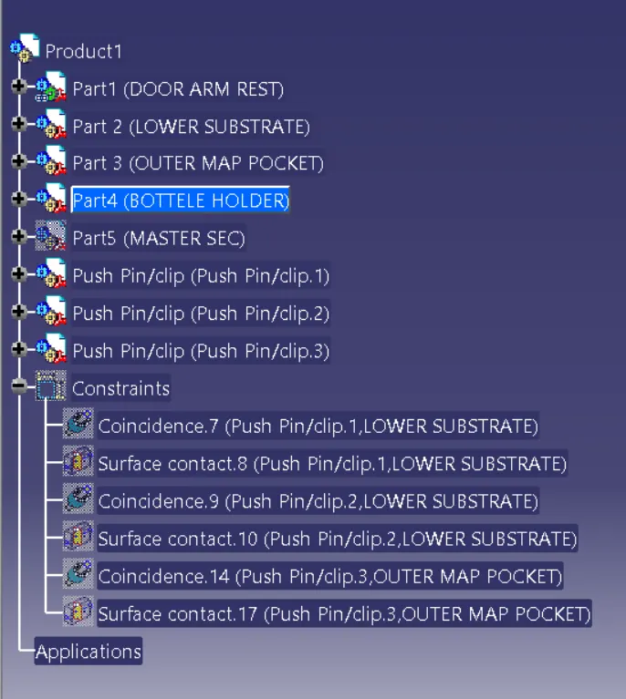
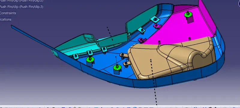
PUSH PIN ASSEMBLY :
- First import the push pin from file in assembly workbench ,
- Then make coincidence with dog house.
- and make surface contact with dog house. as shown in below.
FLANGE:
create a flange for attachment of heat stakes and locators at the lower substrate.
CREATION OF PARTING LINE:
A parting line is used to the difference between core and cavity.