Week 11 - Final project
AIM: To design the car door inner panel with reference to given Class-A surface by using given mastersection, creating attachment features and performing draft analysis to check the manufacturing feasibility of the component by using software CATIA V5.
Objective: The project deals with the explanation of method followed to develop door trim inner panel. In this with the given Class-A surface, Class-B surface and Class-C surface were created along with the tooling axis. Other attachment features were also created for assembly of the different components of door trim.
Introduction:
The inner door panel is an aesthetic and functional component in a car, it is the interface between the car interior and the inner working of door. Inner door panel usually consists of armrest, map pocket, bottle holder, handle bar, other switches, upper and lower substrate, storage compartments, convenience (puddle) lights and locking mechanism. Nowdays door panel is made of plastic material like polypropylene, ABS etc. which helps in making lightweight and complicated shapes of door panels.
The manufacuring Process of plastic door panel is called Injection molding. In this manufacturing process the heated molten plastic material is injected into the mould between core and cavity and cooled down to form a solid plastic component.
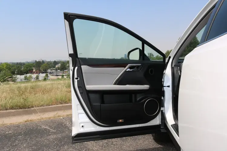
GIVEN SURFACE
REFERENCE SURFACE: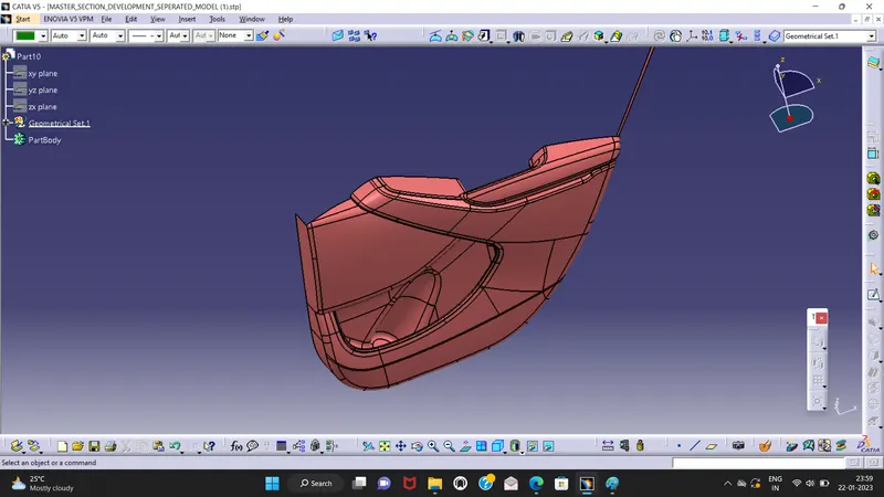
MASTERSECTION: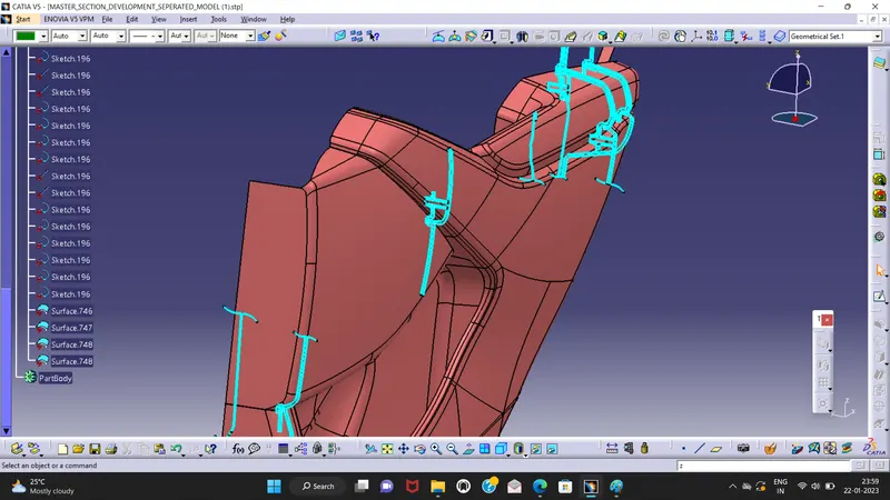
Components included in door panel
- Map pocket
- Bottle holder
- Lower substrate
- Armrest
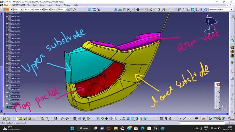
UPPER SUBSTRATE:
TOOLING AXIS:
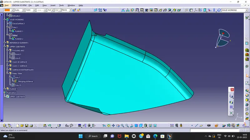
Why we need to create a tooling axis because of we need to eject a product from the mold.when using this tooling axis direction is easy to eject this easily.step 1 we create a point from the given class surface.then use a line normal to z axis.in some case this method is invalid so use bisecting method.then create a some apperance to the line be like colour,dot line ,thickness....for differnce to the another line
CLASS B SURFACE
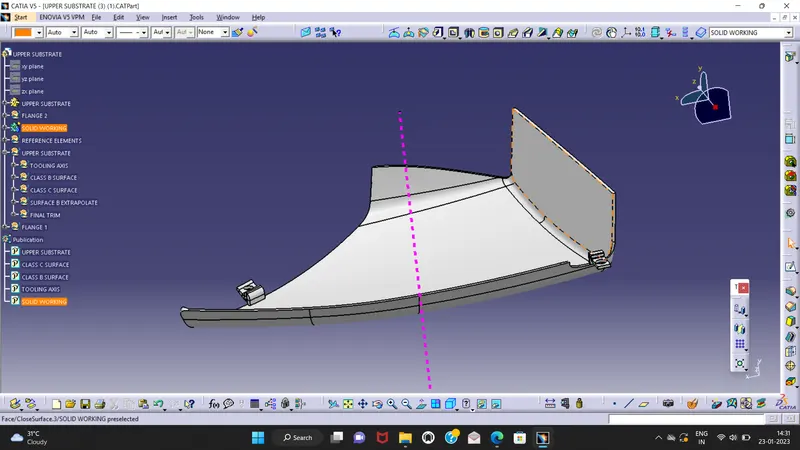
Class B surface will create depond upon the class A surface thickness be like the consideration of the given Mastersection
CLASS C SURFACE:
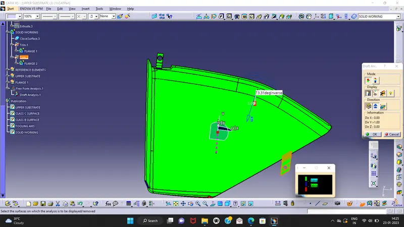
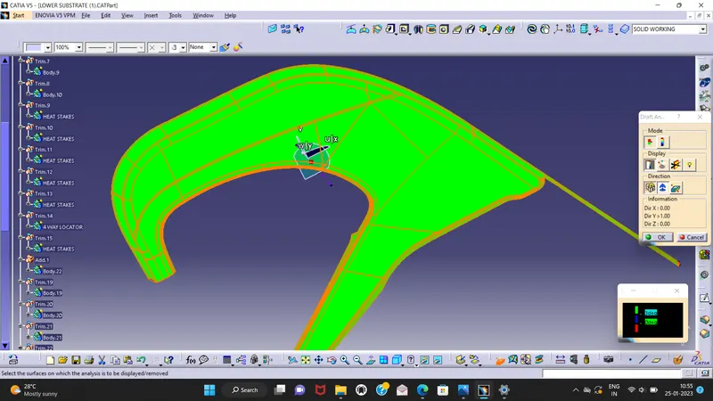
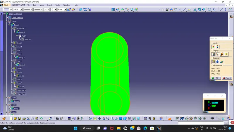
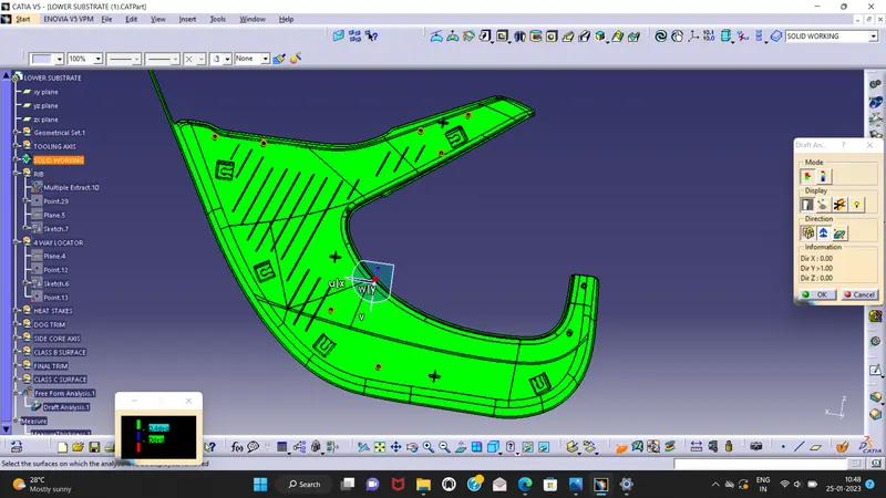
DRAFTING ANALYSIS:
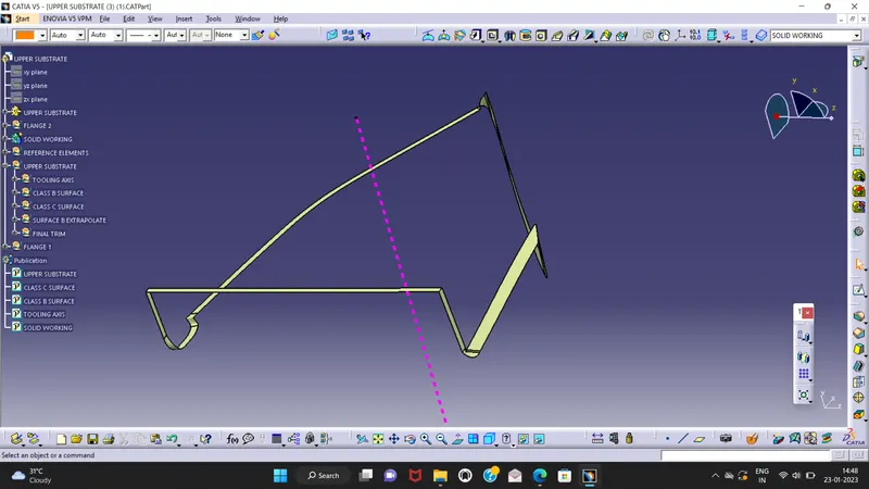
- Go to insert < analysis< feature draft analysis.
- Compass is fixed on the tooling axis.
- Then we click on the surface it showing different colour. This colour is used to analysis the drafting value of surface with the help of analysis table.
- It is zero-degree draft component. So, we no need to take drafting analysis. If we take it will show zero-degree draft angle
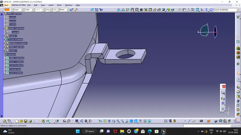
FLANGE:
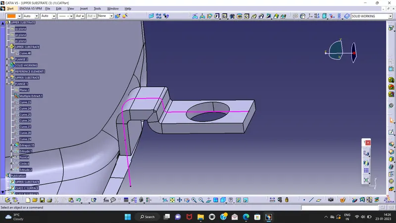
FLANGE CREATION DEPONDS UPON MASTERSECTION:
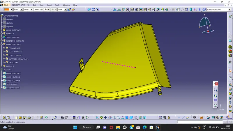
FINAL OUTPUT OF UPPER SUBSTRATE:
2.MAP POCKET:
CLASS A SURFACE:
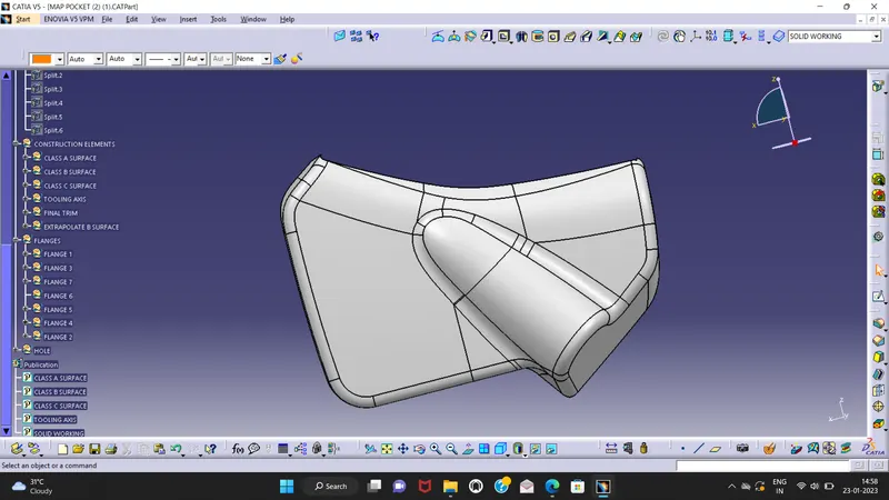
TOOLING AXIS:
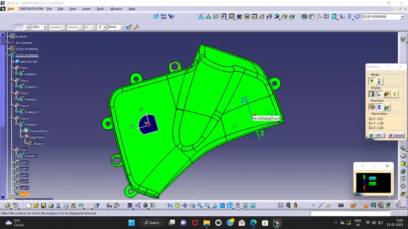
The creation of tooling axis of map pocket is the tool of moment of inertia to create a centre of graviy of the class A surface and point.then create a line normal to the z axis.in case some blue colour indicate in class A surface when using a draft analysis.change the tooling axis when the class a surface is fully green.
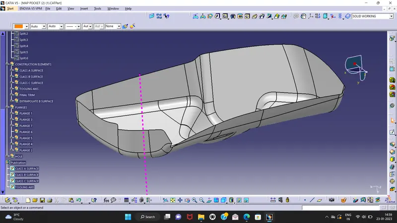
CLASS B SURFACE:
The creartion of class b surface is offset from class A surface.the distance between class a and class b surface is taken from the given mastersection.The thickness is 2.5mm
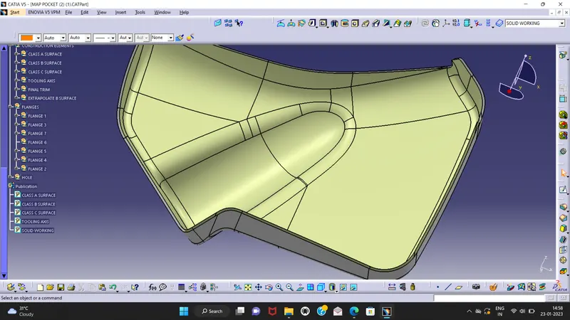
CLASS C SURFACE:
why we want to create a class C surface because of there has no any gap when convert to solid.first we extract the boundry of class A surface.then we use a sweep to option in draft drection with the consideration of tooling axis.the draft of class C surface is 3 degree for the purpose of when the part is eject from the mold get easily.
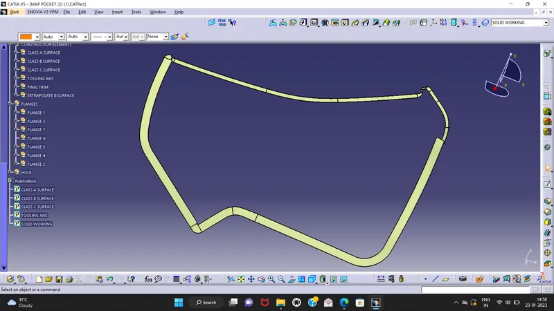
DRAFT ANALYSIS OF A MAP POCKET:
 FLANGE CREATION:
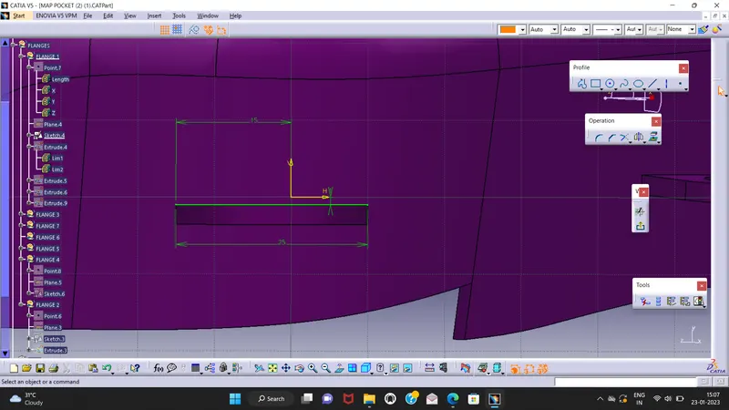
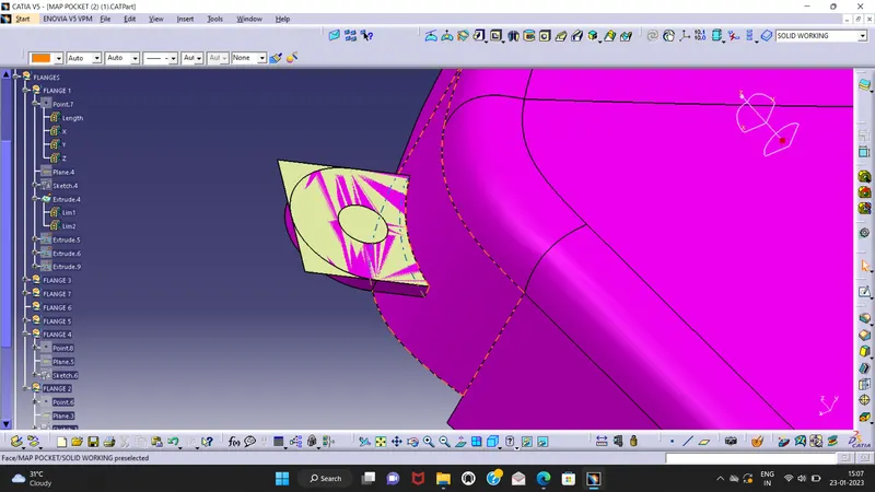
In map pocket did not any mastersection for creation of flange.so we have to create flange in our self with the consideration of design rules.first we extract a surface then create a plane and create a line for length.then go to generative shape design extrude 20 mm distance normal to direction.then thicken the surface.
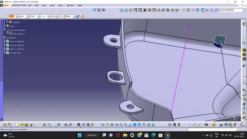
FINAL OUTPUT IN MAP POCKET AFTER INSERT A ENGINEERING FEATURES:
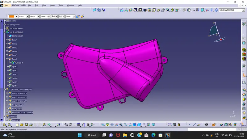
3.ARM REST:
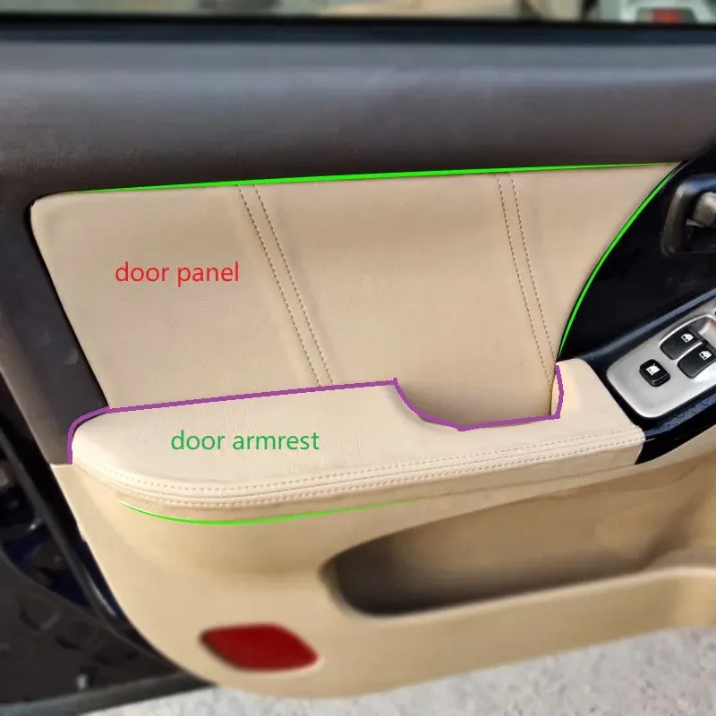
ARM REST which is used to take rest of arm while traveling.These car armrests are adjustable, comfortable and elegant. It is easy to fit in your car and is also extremely simple to maintain. It is directly mounted on the car seat frame while giving the ultimate support to the drivers arm
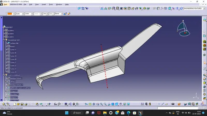
Improper class A surface:
The given class A surface of arm rest is improper.first we want to clear the problem of class A surface using extract, multisection,join tools before start a process.
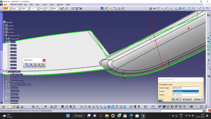
After solve the problem of class A surface in arm rest:
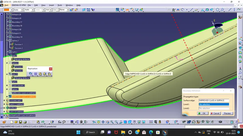
TOOLING AXIS OF ARM REST:
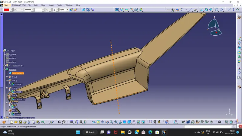
CLASS C SURFACE:
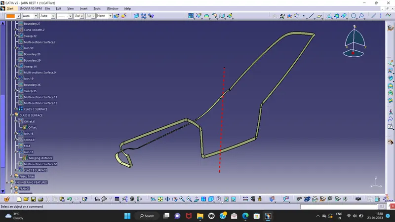
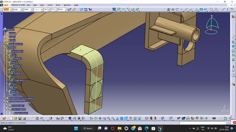
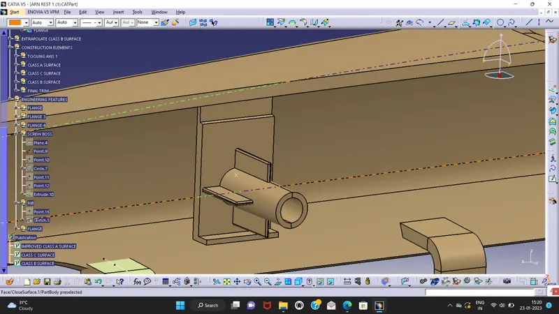
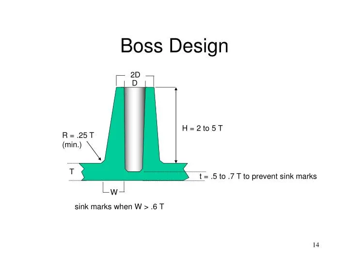
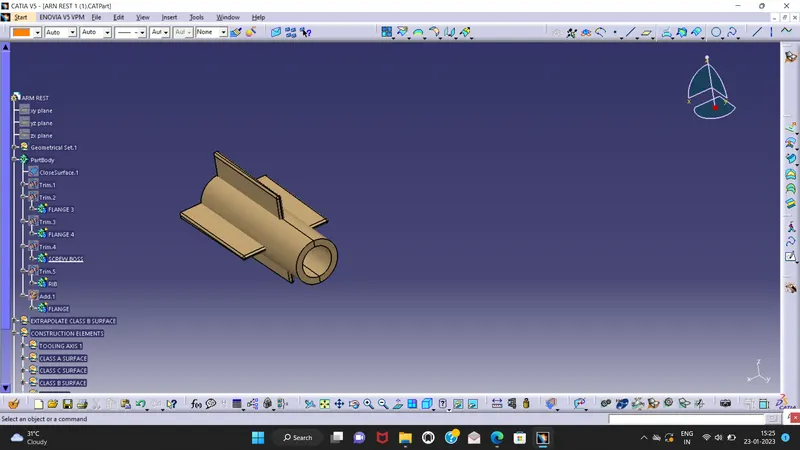
SCREW BOSS:
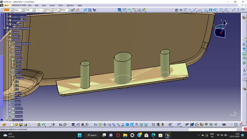
Take a cut for joining part of heat stakes:
LOWER SUBSTRATE
CLASS A SURFACE:
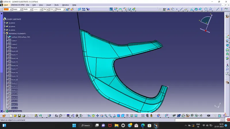
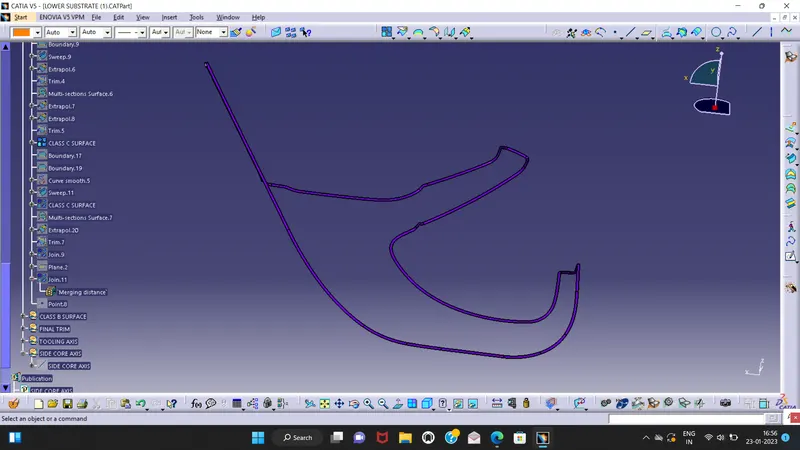
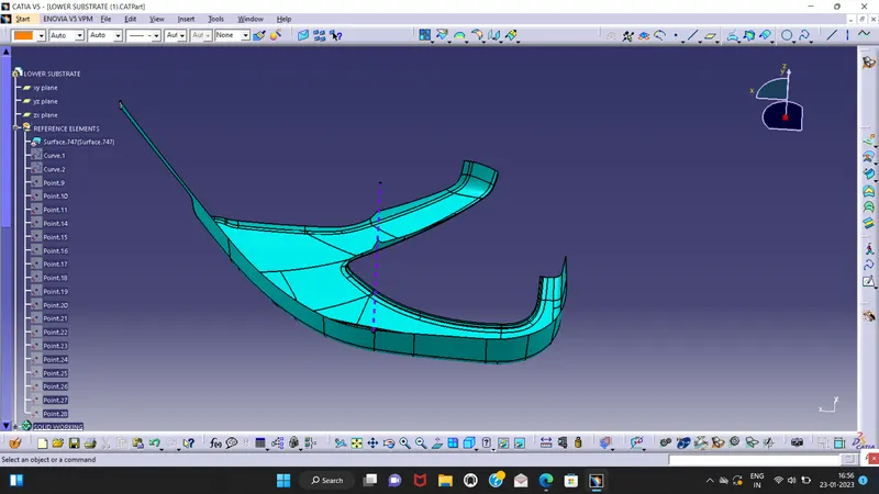
CLASS C SURFACE:
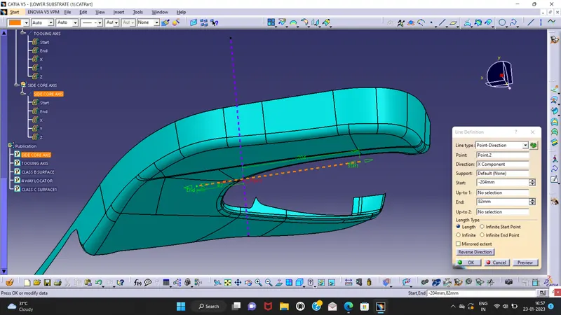
SIDE CORE AXIS:
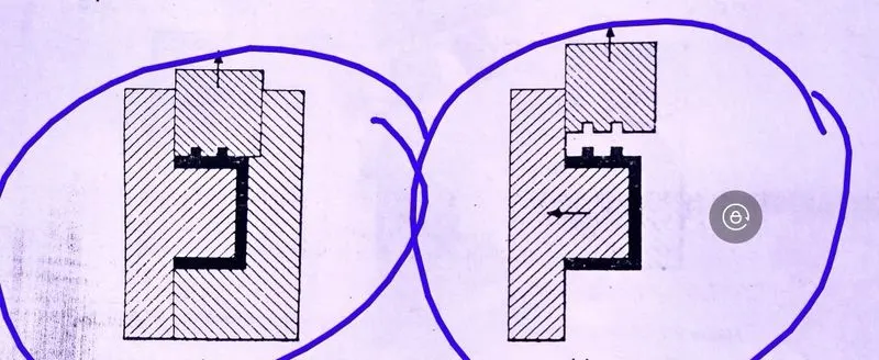
Side core axis is used to eject a part of difficult shape in side of the part.
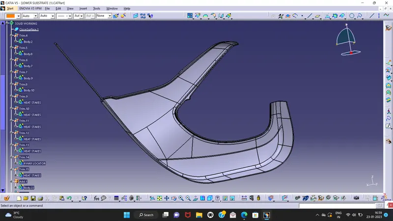
SOLID WORKING:
After convert a part of surface to solid by using close surface:
INSERT A ENGINEERING FEATURES IN LOWER SUBSTRATE
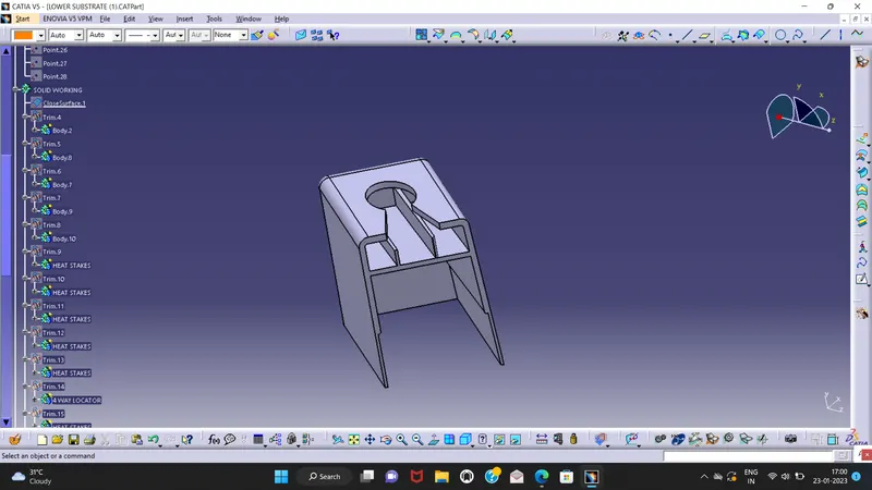
DESIGN RULES FOR DOG HOUSE:
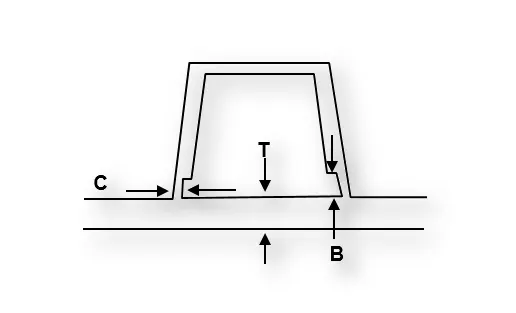
- "C" is where the doghouse contacts the backside of the surface.
- Doghouse wall thickness at the intersection of the part wall ( C ) should be 40% or less than the main wall stock ( T ).
- The height of ( B ) should be between 3.0 – 6.0 mm.
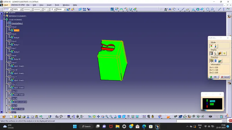
DRAFT ANALYSIS FOR EXTERNAL SIDE DRAFT USING TOOLING AXIS:
The external face of dog house draft is 1.5 degree.
The internal face of dog house draft is 0.5 degree.
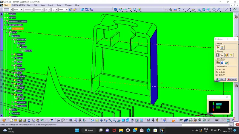
4 way locator:
4-way mean you prevent movement at 2 axes (+X, -X, +Y and -Y) on the plane. Generally, you have cylindrical pin on the fixture and circular hole at workpiece part.
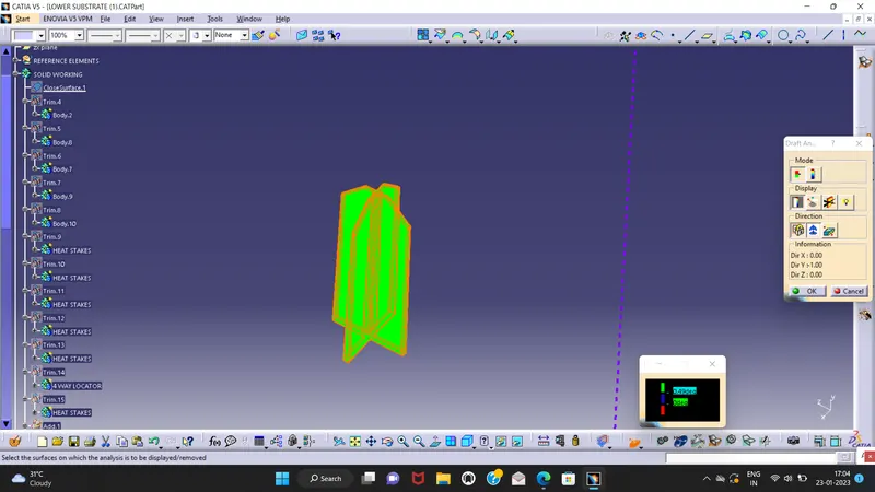
HEAT STAKES:
Heat stakes method which is used to assemble method of automotive plastic design.Assemble of two part using heat stakes.Heat staking also known as thermoplastic staking is the process of joining two dissimilar materials together.
heat stakes should also draft the angle of 0.5 degree consideration of our engineering standard rules.
RIB:
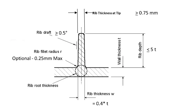
Ribs are used in plastic parts to increase bending stiffness without increasing plastic part thickness. In plastic part design, recommended rib thickness is 0.5 to 0.75 times the nominal wall thickness to avoid shrinkage in injection molded parts. To avoid thin sections in the injection mold.
PUCH CLIP:
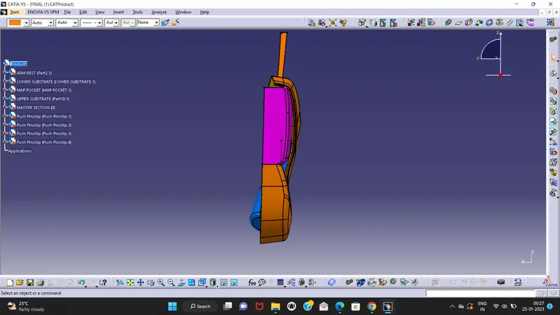
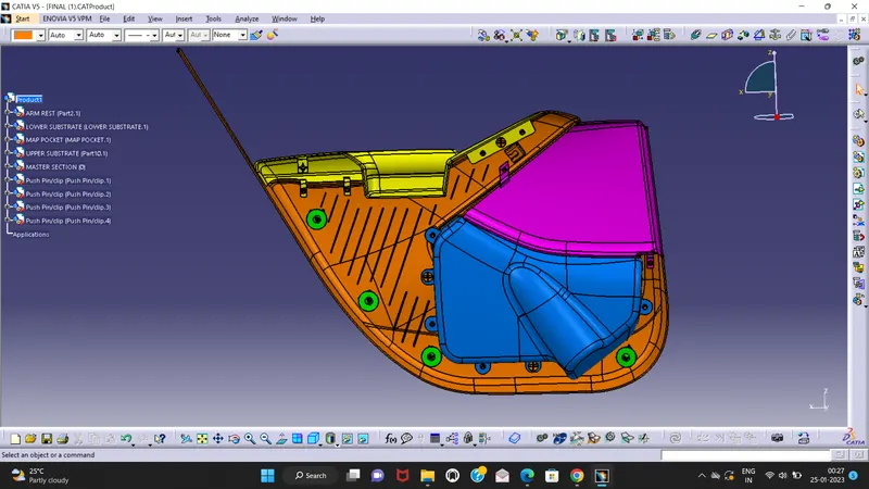
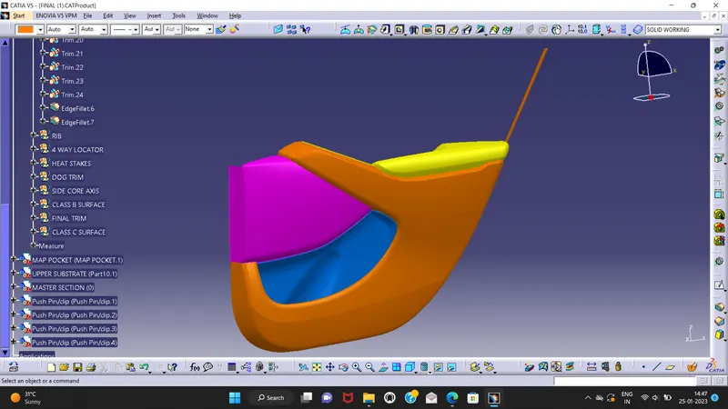
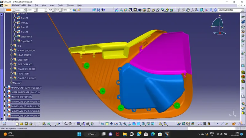
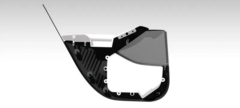
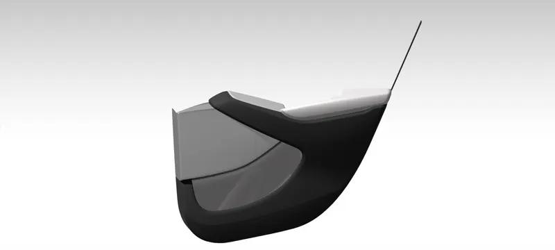
FINAL OUTPUT AFTER RENDERING:
CONCLUSION:
This is the design of car door trim in automotive industry.I know about the details of what the procedure and engineering features are following in industries.