Week 11 - Final project
Aim : Developing a Door Trim Panel.
- To Create thickened part using master section for reference.
- To Create the mounting features as per design guidelines in the industry and with master sections.
- To Apply material details.
- To be done Draft analysis & Tooling analysis.
- To Create parting lines and check tooling feasibility.
Given Inputs :
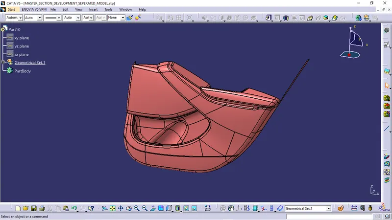
- Class A surface of door trim panel.
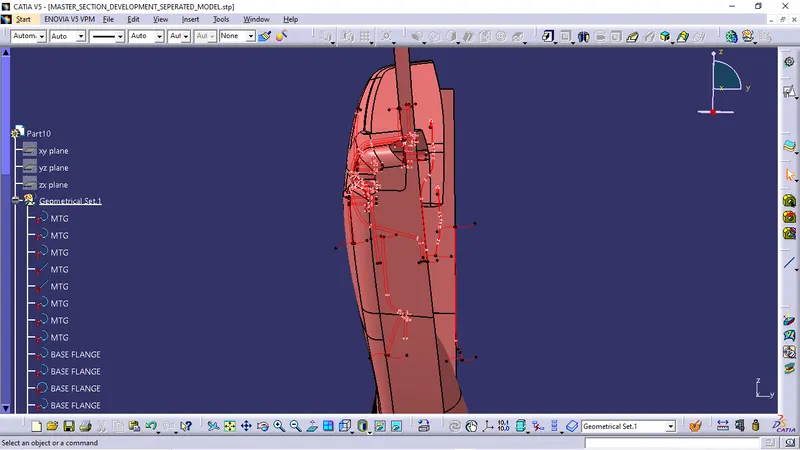
- Master sections.
Class A surface :
Master Sections :
Introduction :
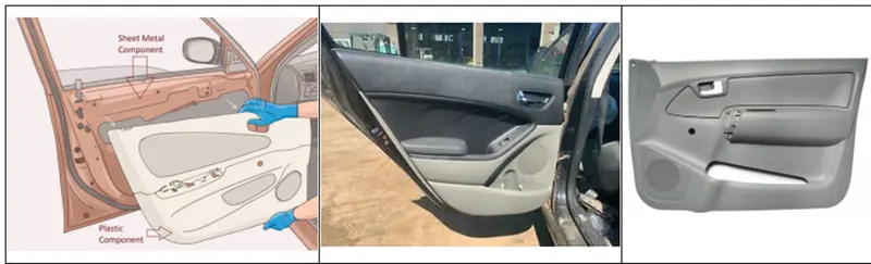
The door panel is the interference between the interior of the car and the inner workings of the door. Generally, the door panel is divided into parts of easy designing like arm rest, map pocket, lower substrate, bottle holder, these requires one of the toughest requirements among the interior parts of the car. This should be designed to with stand the load while being less than 2mm in the thickness and also protect the occupants during collisions. Door currently has an inner full width panel consisting of electronic windows. Central locking system and speakers. These panels typically consist of a covered with either textiles or plastics.
The ten stages in automotive product life cycle developement are listed below .
- Concept sketch
- Styling class A
- Feasilbility check
- Concept validation
- New product design
- Product developement
- Prototyping
- Design validation
- Pilot production
- Mass production
From the above stages , it isin stage 5 that new product is developed and validated from class A surface . The objective is to design class B and class C surface from given class A surface and create a solid body from it using softwares like CATIA V5, solidworks or solidedge taking into consideration the draft analysis which makes the component suitable for production using injection molding process .
Given below is the procedure to create a new plastic component from given class A surface .
- Creation of tooling axis
- Creation of class b surface
- Creation of class C surface
- Creation of closed body
Draft Analysis .
Draft analysis is done to ensure that the designed part is manufacturable based on the draft conditions applied. It is done to ensure the proper ejection of the component from dies(for metals) or molds(for plastics). The basic idea is to ensure that the tooling axis has to be created in such a wat that it has no parallel surface profiles of the component so that the ejection of the components can be ensured . Tooling axis is the axis along which cavity and core are closed and opened .
Development Of Door Trim Panel :
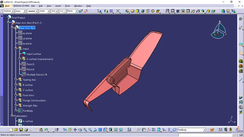
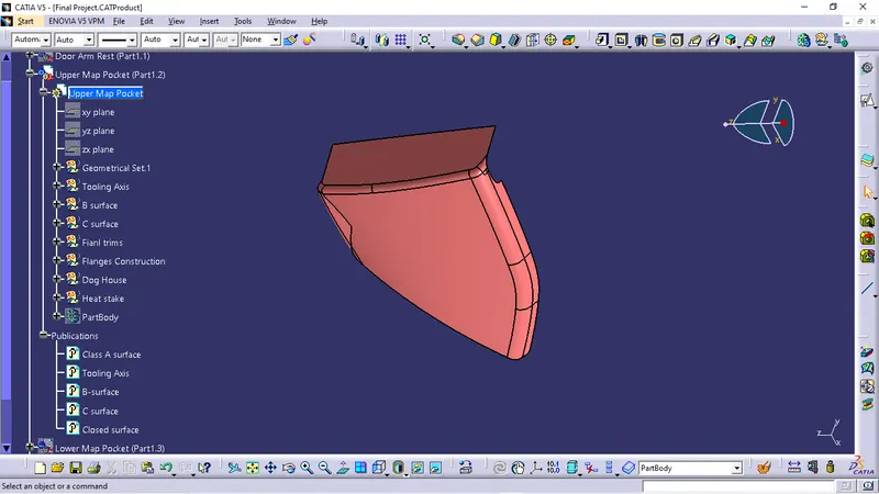
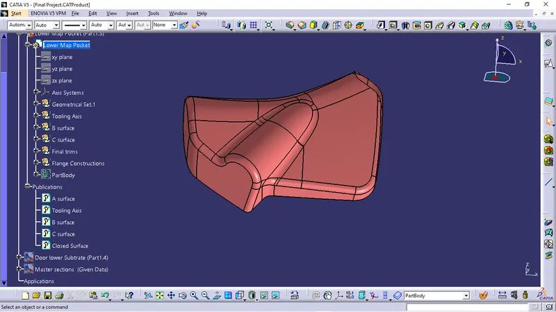
The given Class A surface is in single part file. We need to divide the single part file in to assembly file and divide the surfaces and name it.
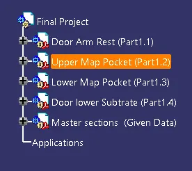
After Dividing :
Door Arm Rest :
Class A surface
Upper Map Pocket :
Lower Map Pocket :
Lower Subtrate :
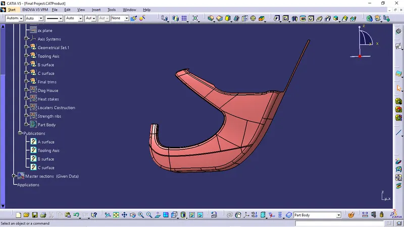
The above shown Class A surfaces to be thicken and provide engineering attachement features one by one.
Door Arm Rest Procedure :
- Class A surface checking for patches.
- Class A surface improvements.
- Tooling Axis creation.
- Draft analysis for Class A surface.
- Class B surface creation.
- Class C surface creation.
- Joining of Class A+C+B.
- Converting to solid body.
- Creation of attachement features.
- Creation of engineering features.
- Draft Analysis to part body.
Class A Surface Checking for Patches :
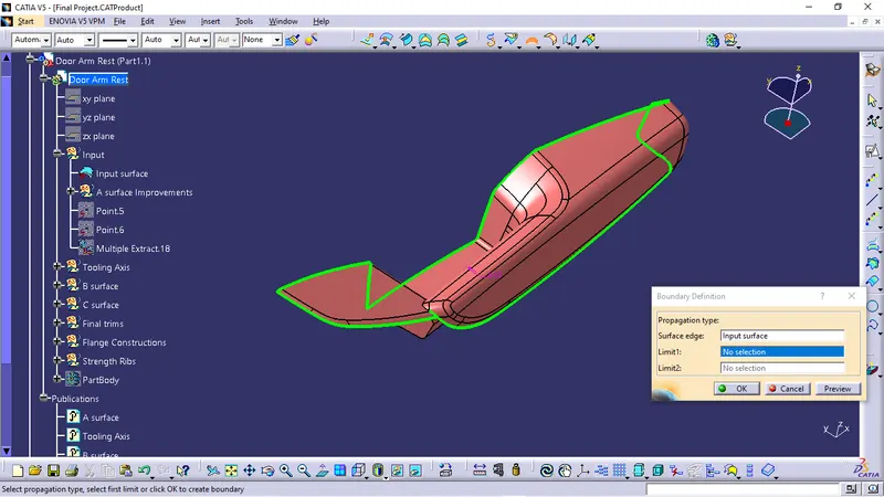
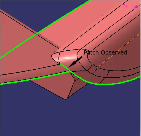
- This can be done using either boundary or join feature.
- Patches are showed in highlighted green colour edes.
Class A surface Improvements :
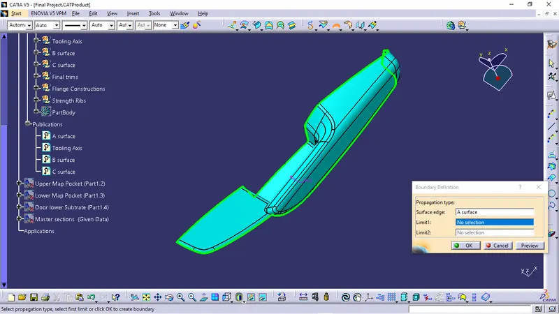
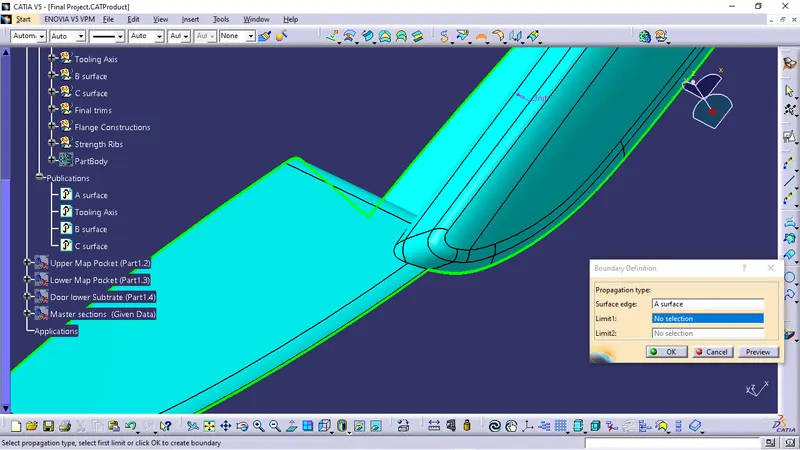
- The patches are covered by extrapolating the edges wherever required and trimming.
Tooling Axis :
- The tooling axis is drawn by using Point and Direction option in line feature.
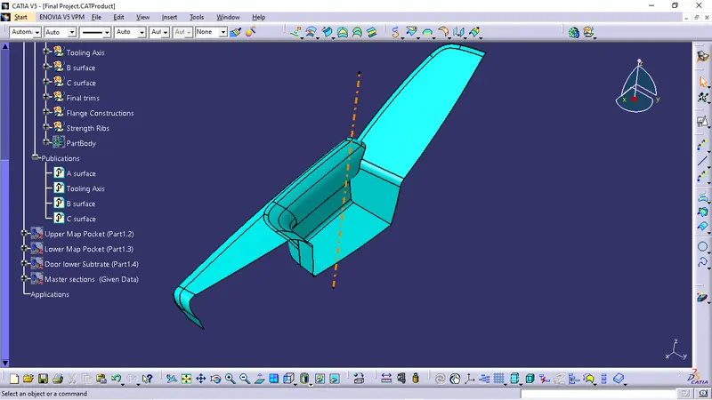
The Orange center line is tooling Axis.
Draft Analysis to Class A surface :
- Draft analysis done to class A surface along tooling direction with 3degree draft angle to check the tooling axis proper or not.
- This should clear the draft analysis for all faces.
- Cleared faces shows in green (Above 3degree).
- Non cleared faces shown in Red (Below 0degree).
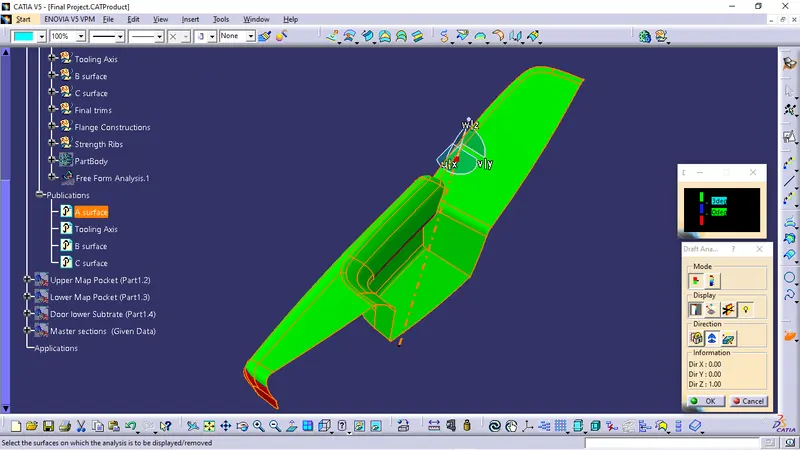
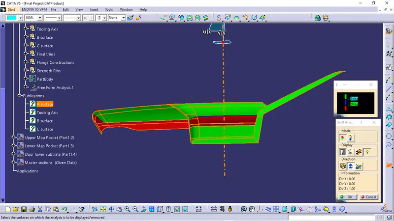
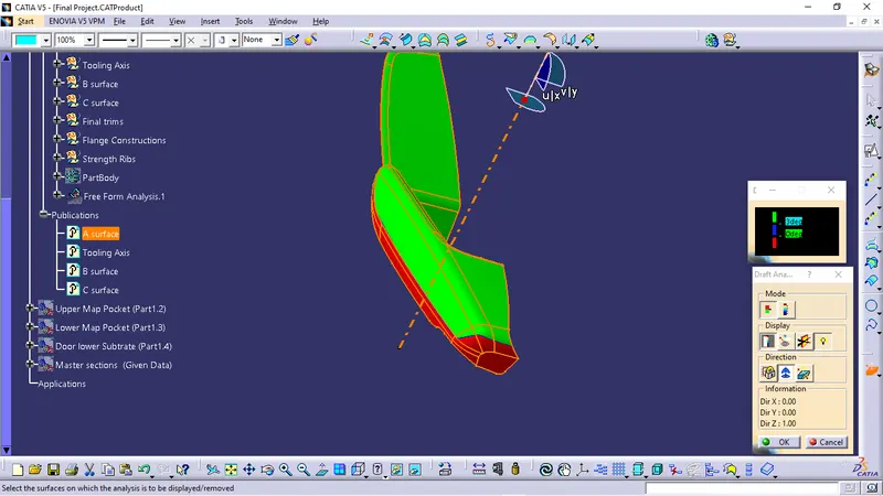
- Some faces are not clearing draft analysis at 3degrees and showing in red which means they are below 0 degree.
- This is due to improper Class A surface.
- For more details on draft analysis the PPT is submitted.Please Refer.
Class B surface:
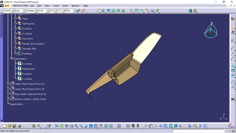
- Class B surface can be done by offsetting the Class A surface by 2.5mm.(Followed by Master section thickness)
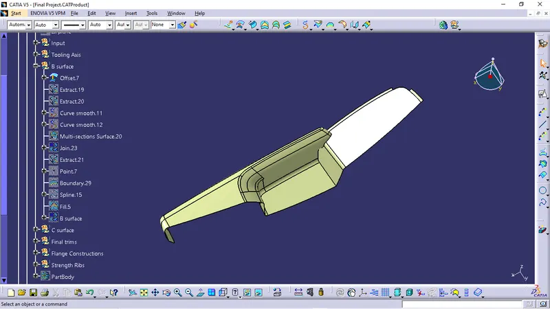
- Observed patches should be recreate and make a proper B surface.
Patches Observed surface :
Proper B surface :
Class C Surface :
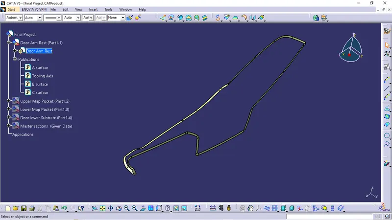
- Class C surface is the surface that joins the Class A and Class B surface.
- This should be done along Class A surface edges until and above the Class B surface.Then only it is possible to trim with Class B surface.
Class A+B+C Joining :
- Class A and Class C can join by using join feature.
- Now Class A+C surface should trim with Class B surface.
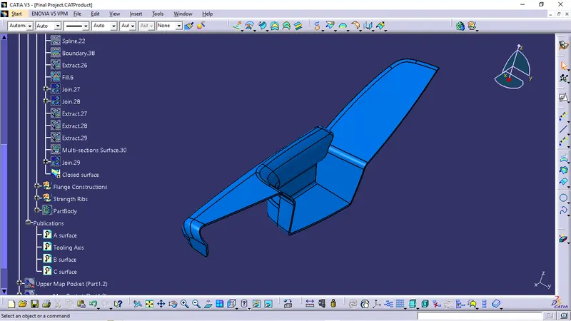
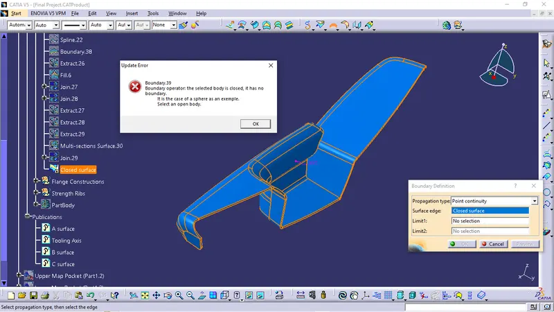
- A proper closed surface to be create.
- We can use boundary option to check weather it is properly closed or not.
- If the surface is properly closed then a error dialouge box appears like below shown.
Converting To Part Body:
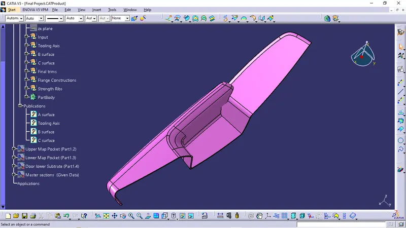
- The above closed surface is now converted in to part solid body by using Close surface feature in Part design workbench.
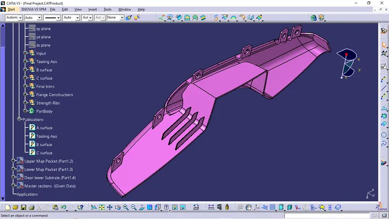
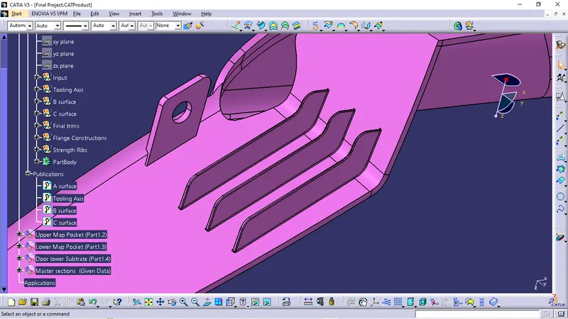
Attachment Features :
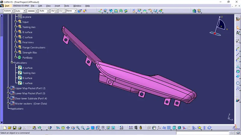
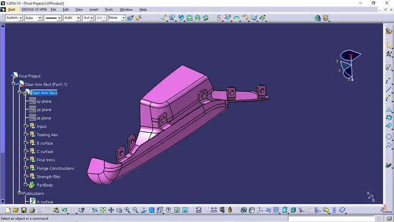
- This features are required to attach one part to another part.
- Like Flanges,Heat stakes,Screw Bosses and Dog houses.
- This is done by following the master section and some are by own.
Engineering Features :
- The engineering features are used to strengthen the part and to produce the part without any deviations.
- By following the standard engineering features the part can be produced without any issues.
- Like Ribs,Locaters etc.,
Draft Analysis :
- Draft analysis done to part body along tooling axis and side core tooling axis with required draft angle. The results are shown below.
Main tooling axis Draft analysis :
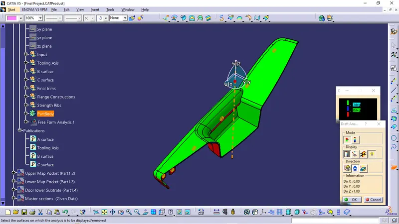
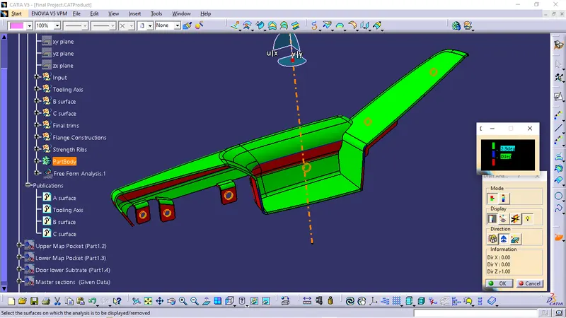
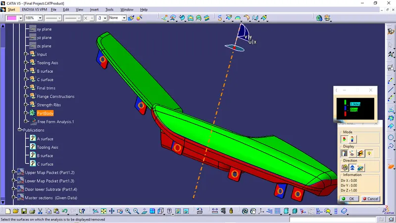
- Some faces are not clearing with main tooling axis due to improper Class A surface.
- Some are showing in blue which means it is below 3degree and above 0degree.
Side Core Tooling axis :
- The Violet center line is Side core tooling axis.
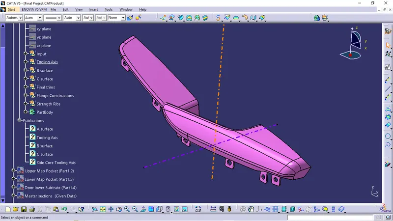
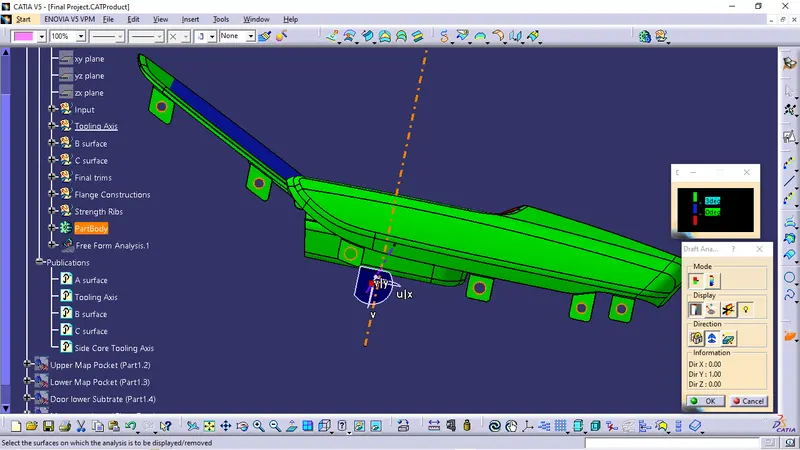
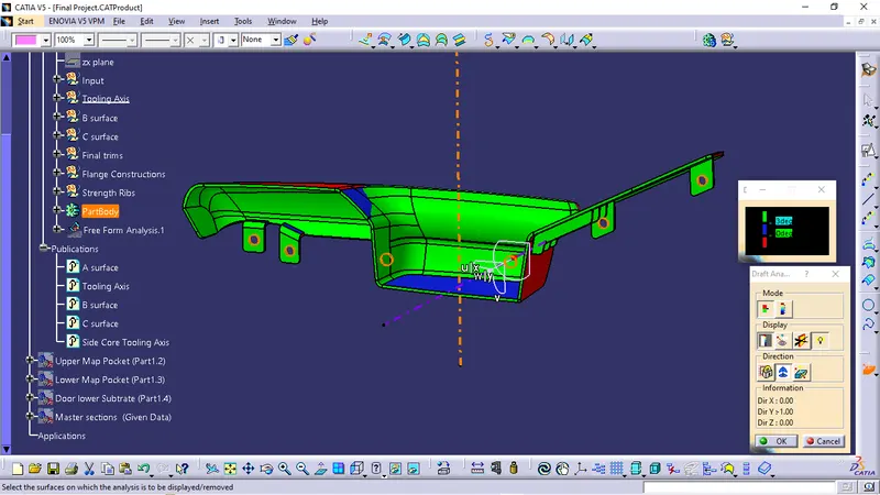
For more details on draft analysis a proper PPT is submitted.
Upper Map Pocket Procedure :
- Class A surface checking for patches.
- Class A surface improvements.
- Tooling Axis creation.
- Draft analysis for Class A surface.
- Class B surface creation.
- Class C surface creation.
- Joining of Class A+C+B.
- Converting to solid body.
- Creation of attachement features.
- Creation of engineering features.
- Draft Analysis to part body.
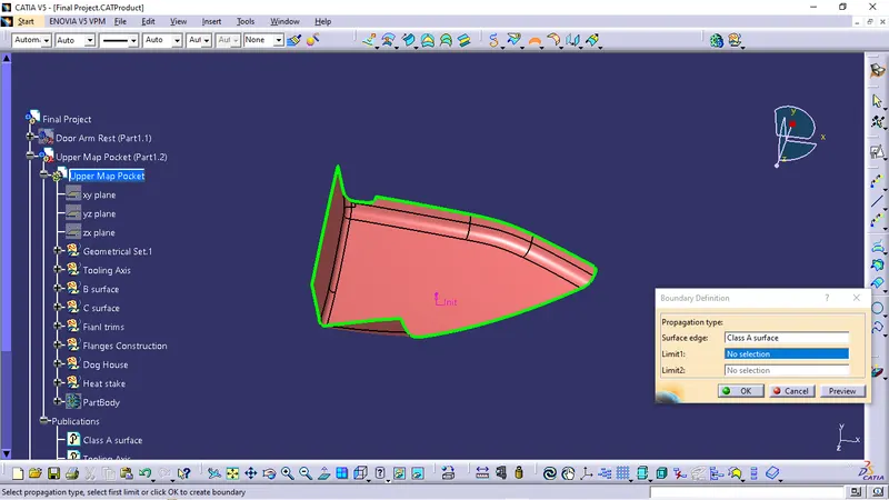
Class A Surface Checking for Patches :
- This can be done using either boundary or join feature.
- Patches are showed in highlighted green colour edes.
Tooling Axis :
- The tooling axis is drawn by using Point and Direction option in line feature.
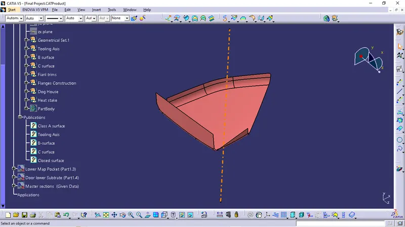
The Orange center line is tooling Axis.
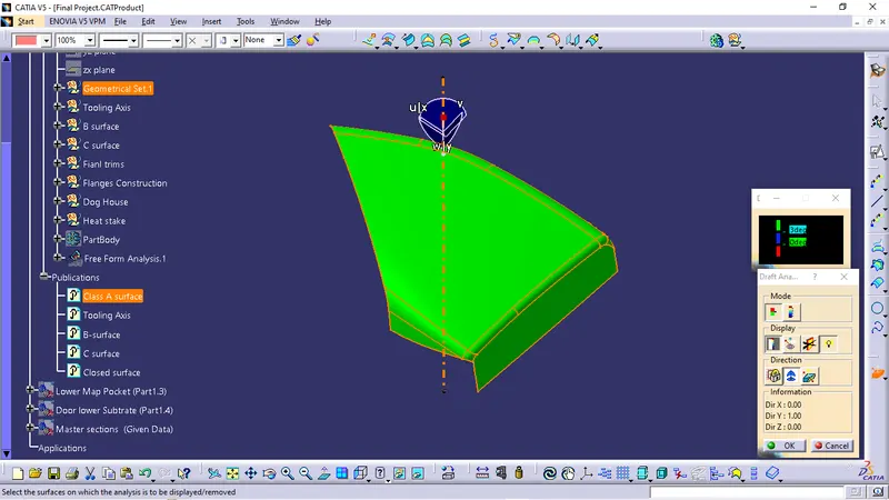
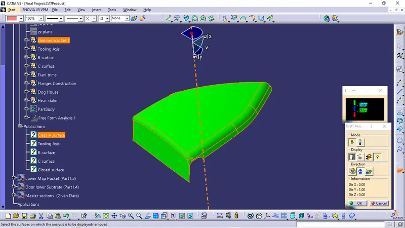
Draft Analysis to Class A surface :
- Draft analysis done to class A surface along tooling direction with 3degree draft angle to check the tooling axis proper or not.
- This should clear the draft analysis for all faces.
- Cleared faces shows in green (Above 3degree).
- Non cleared faces shown in Red (Below 0degree).
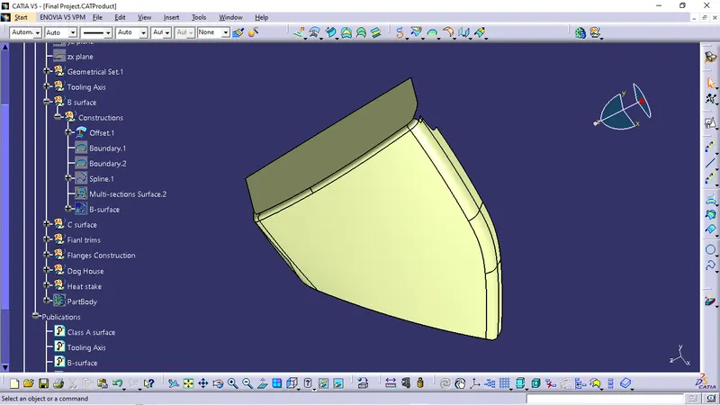
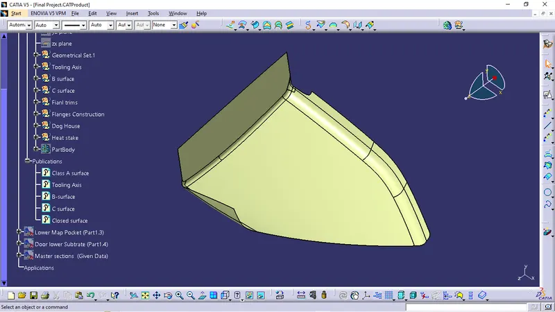
Class B surface:
- Class B surface can be done by offsetting the Class A surface by 2.5mm.(Followed by Master section thickness)
- Observed patches should be recreate and make a proper B surface.
Patches Observed surface :
Proper B surface :
Class C Surface :
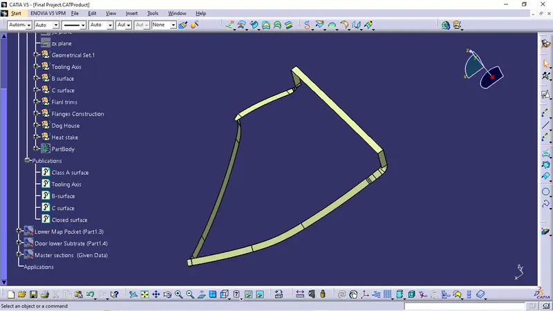
- Class C surface is the surface that joins the Class A and Class B surface.
- This should be done along Class A surface edges until and above the Class B surface.Then only it is possible to trim with Class B surface.
Class A+B+C Joining :
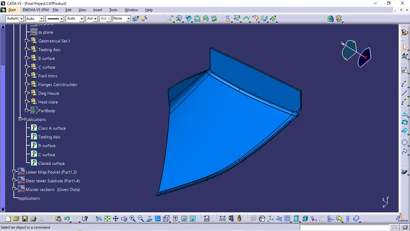
- Class A and Class C can join by using join feature.
- Now Class A+C surface should trim with Class B surface.
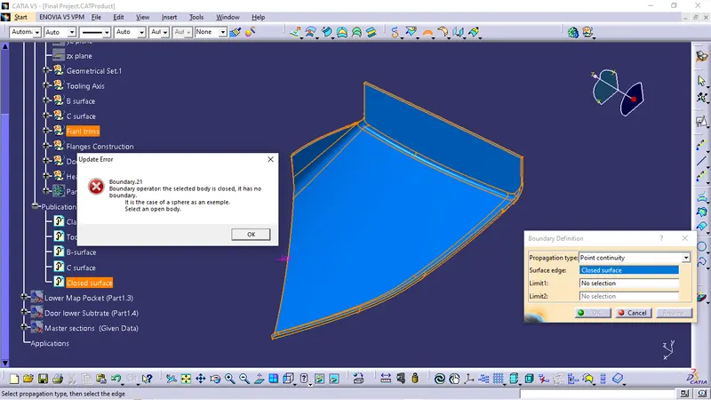
- A proper closed surface to be create.
- We can use boundary option to check weather it is properly closed or not.
- If the surface is properly closed then a error dialouge box appears like below shown.
Converting To Part Body:
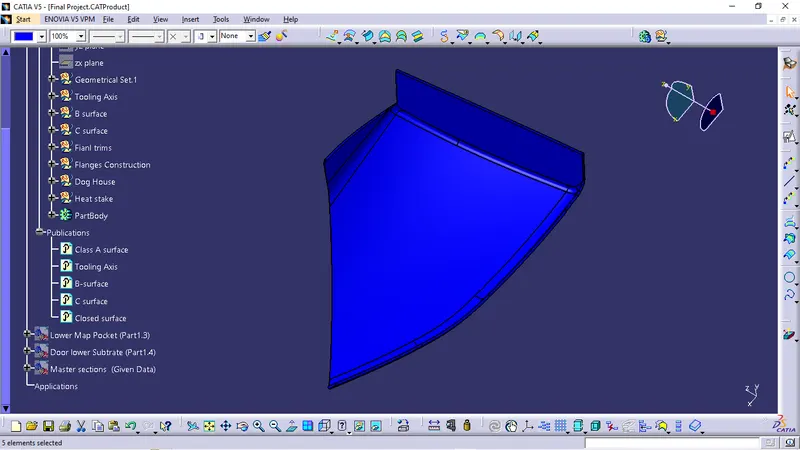
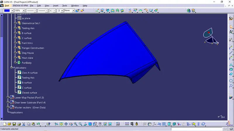
- The above closed surface is now converted in to part solid body by using Close surface feature in Part design workbench.
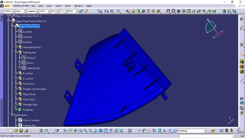
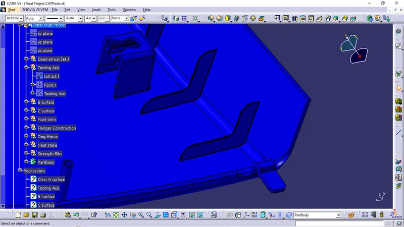
Attachment Features :
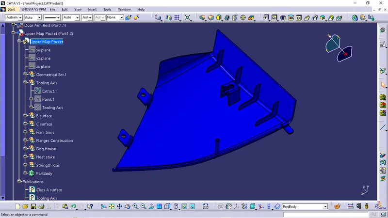
- This features are required to attach one part to another part.
- Like Flanges,Heat stakes,Screw Bosses and Dog houses.
- This is done by following the master section and some are by own.
Engineering Features :
- The engineering features are used to strengthen the part and to produce the part without any deviations.
- By following the standard engineering features the part can be produced without any issues.
- Like Ribs,Locaters etc.,
Draft Analysis :
- Draft analysis done to part body along tooling axis and side core tooling axis with required draft angle. The results are shown below.
Main tooling axis Draft analysis :
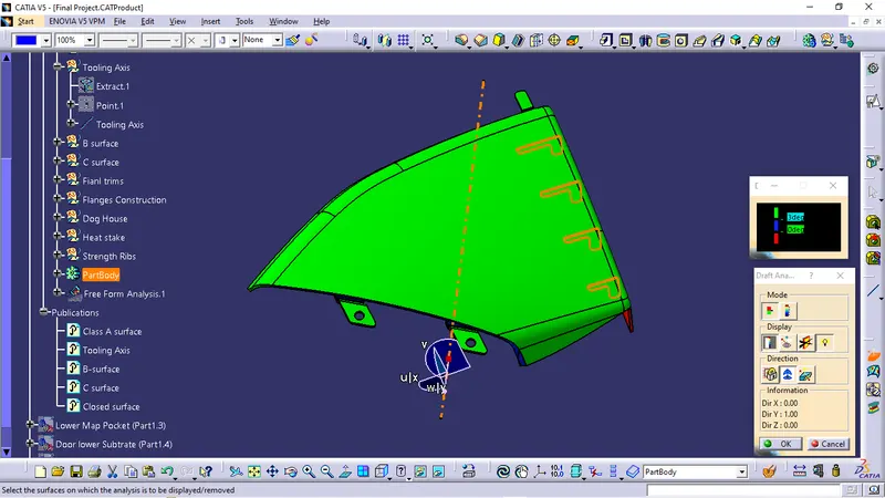
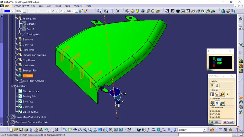
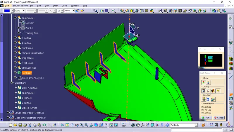
- Some are showing in blue which means it is below 3degree and above 0degree.
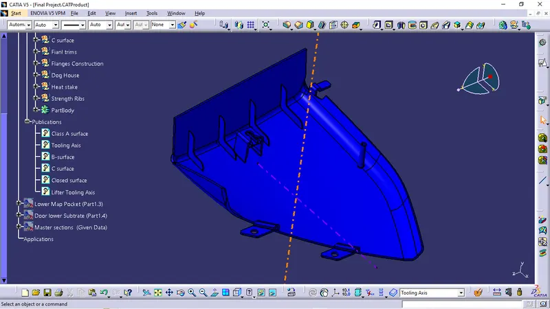
Lifter Tooling axis :
- The Violet center line is Lifter tooling axis.
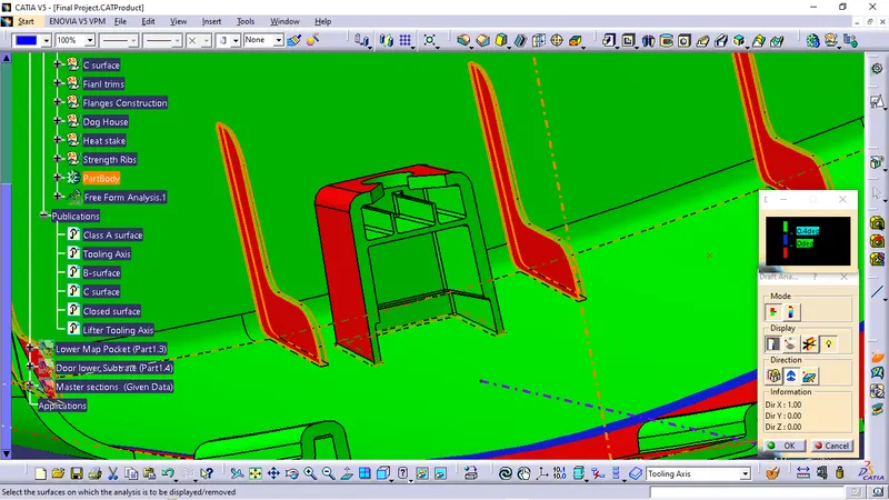
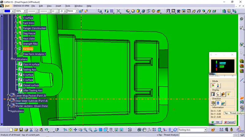
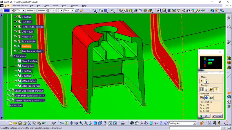
For more details on draft analysis a proper PPT is submitted.
Lower Map Pocket Procedure :
- Class A surface checking for patches.
- Class A surface improvements.
- Tooling Axis creation.
- Draft analysis for Class A surface.
- Class B surface creation.
- Class C surface creation.
- Joining of Class A+C+B.
- Converting to solid body.
- Creation of attachement features.
- Creation of engineering features.
- Draft Analysis to part body.
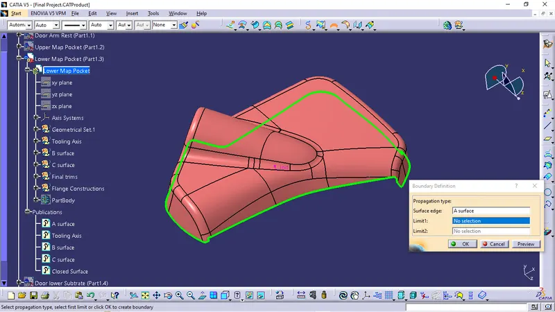
Class A Surface Checking for Patches :
- This can be done using either boundary or join feature.
- Patches are showed in highlighted green colour edes.
Tooling Axis :
- The tooling axis is drawn by using bisecting line option in line feature.
- For bisecting two more line drawn in sketches with reference to intersecting the surface walls.
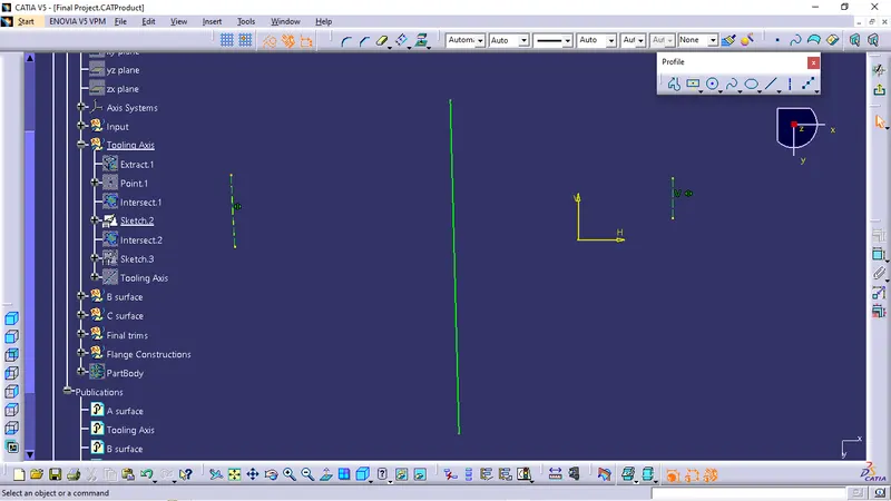
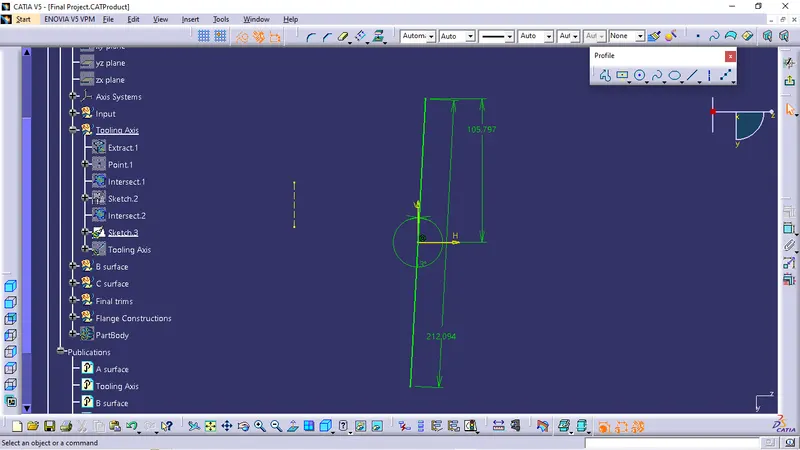
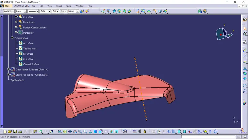
The Orange center line is tooling Axis.
Draft Analysis to Class A surface :
- Draft analysis done to class A surface along tooling direction with 3degree draft angle to check the tooling axis proper or not.
- This should clear the draft analysis for all faces.
- Cleared faces shows in green (Above 3degree).
- Non cleared faces shown in Red (Below 0degree).
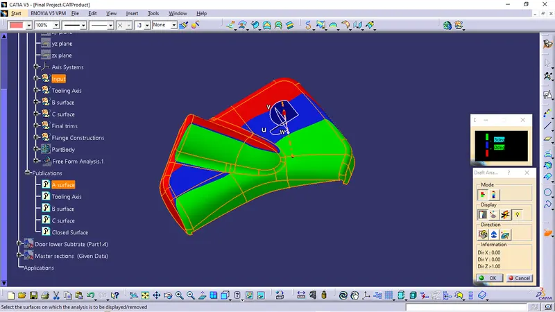
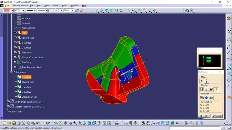
- Some faces are not clearing draft analysis at 3degrees and showing in red which means they are below 0 degree.
- This is due to improper Class A surface.
- For more details on draft analysis the PPT is submitted.Please Refer.
Class B surface:
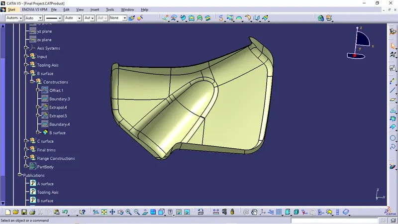
- Class B surface can be done by offsetting the Class A surface by 2.5mm.(Followed by Master section thickness)
- Observed patches should be recreate and make a proper B surface.
Class C Surface :
- Class C surface is the surface that joins the Class A and Class B surface.
- This should be done along Class A surface edges until and above the Class B surface.Then only it is possible to trim with Class B surface.
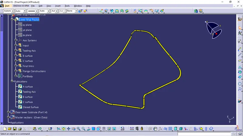
Class A+B+C Joining :
- Class A and Class C can join by using join feature.
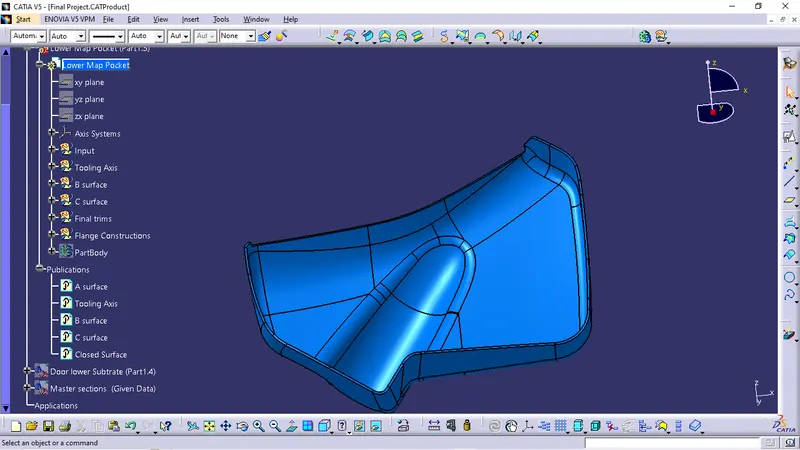
- Now Class A+C surface should trim with Class B surface.
- A proper closed surface to be create.
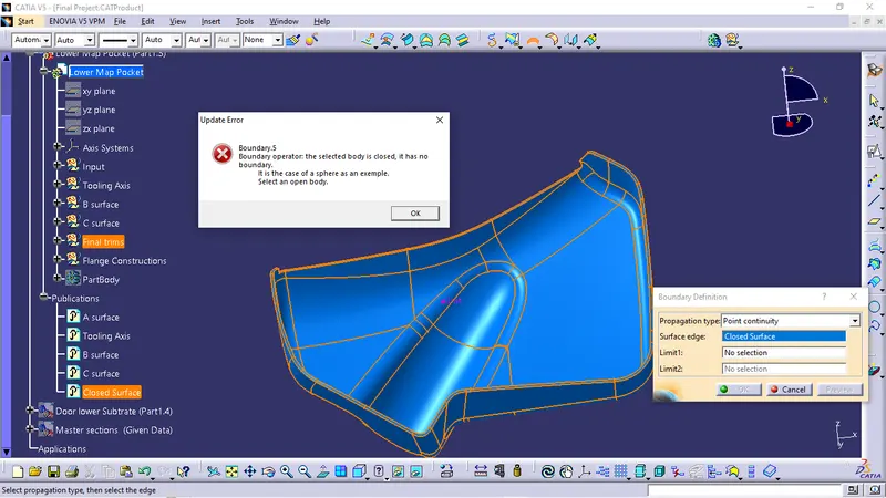
- We can use boundary option to check weather it is properly closed or not.
- If the surface is properly closed then a error dialouge box appears like below shown.
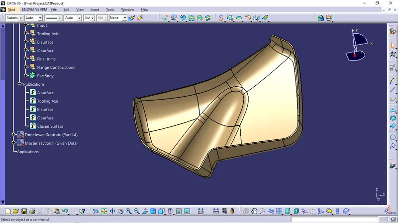
Converting To Part Body:
- The above closed surface is now converted in to part solid body by using Close surface feature in Part design workbench.
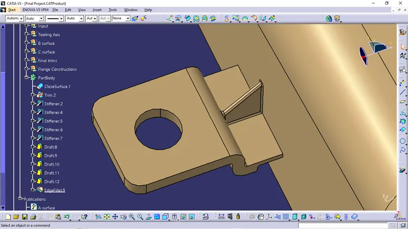
Attachment Features :
- This features are required to attach one part to another part.
- Like Flanges,Heat stakes,Screw Bosses and Dog houses.
- This is done by following the master section and some are by own.
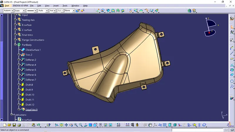
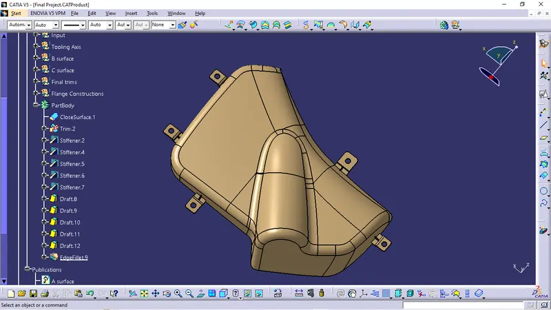
Engineering Features :
- The engineering features are used to strengthen the part and to produce the part without any deviations.
- By following the standard engineering features the part can be produced without any issues.
- Like Stiffners,Ribs,Locaters etc.,
Draft Analysis :
- Draft analysis done to part body along tooling axis and side core tooling axis with required draft angle. The results are shown below.
Main tooling axis Draft analysis :
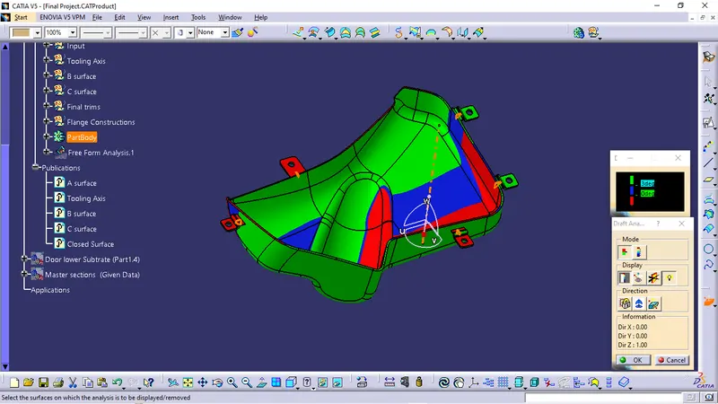
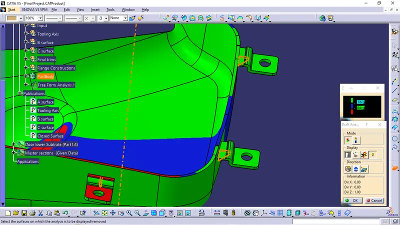
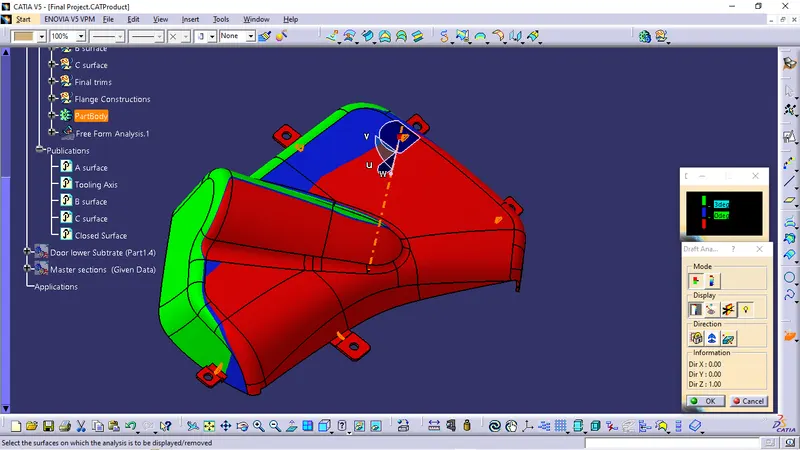
- Some faces are not clearing with main tooling axis due to improper Class A surface.
- Some are showing in blue which means it is below 3degree and above 0degree.
For more details on draft analysis a proper PPT is submitted.
Lower Subtrate Procedure :
- Class A surface checking for patches.
- Class A surface improvements.
- Tooling Axis creation.
- Draft analysis for Class A surface.
- Class B surface creation.
- Class C surface creation.
- Joining of Class A+C+B.
- Converting to solid body.
- Creation of attachement features.
- Creation of engineering features.
- Draft Analysis to part body.
Class A Surface Checking for Patches :
- This can be done using either boundary or join feature.
- Patches are showed in highlighted green colour edes.
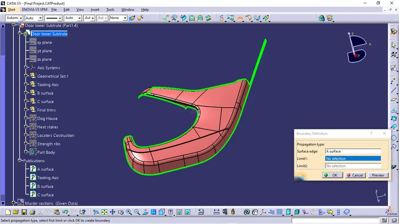
Tooling Axis :
- The tooling axis is drawn by using Point and Direction option in line feature.
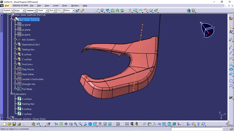
The Orange center line is tooling Axis.
Draft Analysis to Class A surface :
- Draft analysis done to class A surface along tooling direction with 3degree draft angle to check the tooling axis proper or not.
- This should clear the draft analysis for all faces.
- Cleared faces shows in green (Above 3degree).
- Non cleared faces shown in Red (Below 0degree).
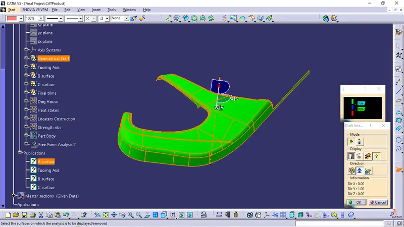
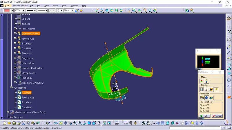
- For more details on draft analysis the PPT is submitted.Please Refer.
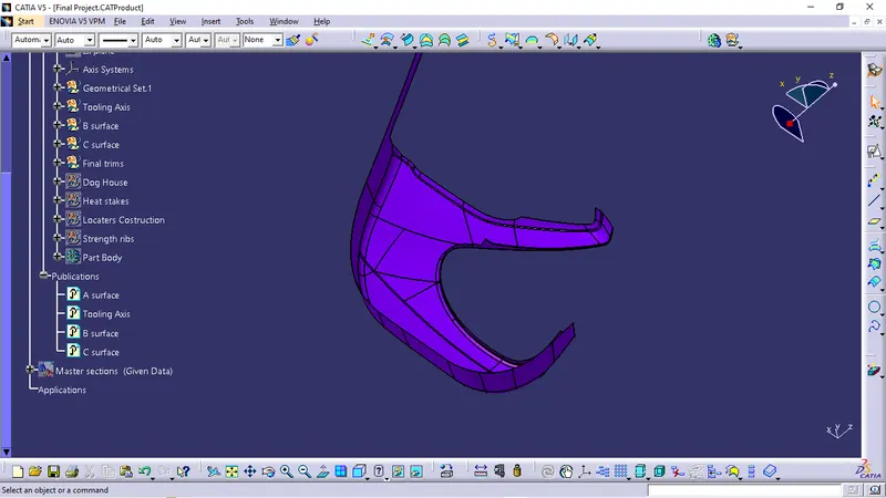
Class B surface:
- Class B surface can be done by offsetting the Class A surface by 2.5mm.(Followed by Master section thickness)
- Observed patches should be recreate and make a proper B surface.
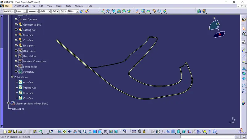
Class C Surface :
- Class C surface is the surface that joins the Class A and Class B surface.
- This should be done along Class A surface edges until and above the Class B surface.Then only it is possible to trim with Class B surface.
Class A+B+C Joining :
- Class A and Class C can join by using join feature.
- Now Class A+C surface should trim with Class B surface.
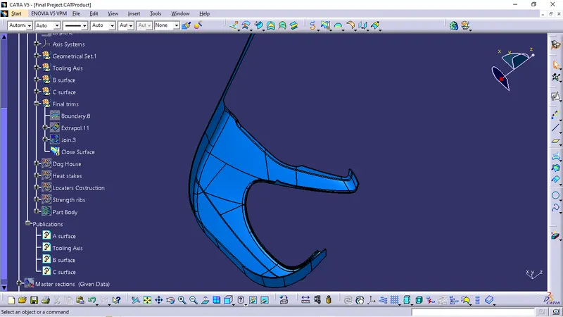
- A proper closed surface to be create.
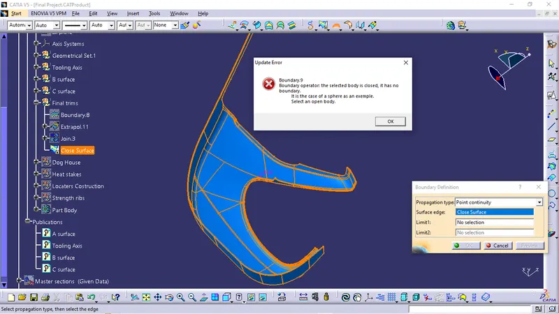
- We can use boundary option to check weather it is properly closed or not.
- If the surface is properly closed then a error dialouge box appears like below shown.
Converting To Part Body:
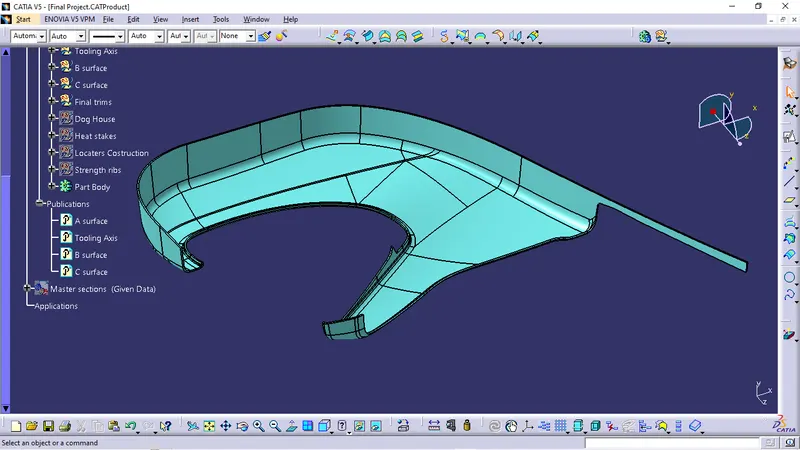
- The above closed surface is now converted in to part solid body by using Close surface feature in Part design workbench.
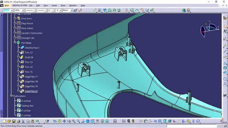
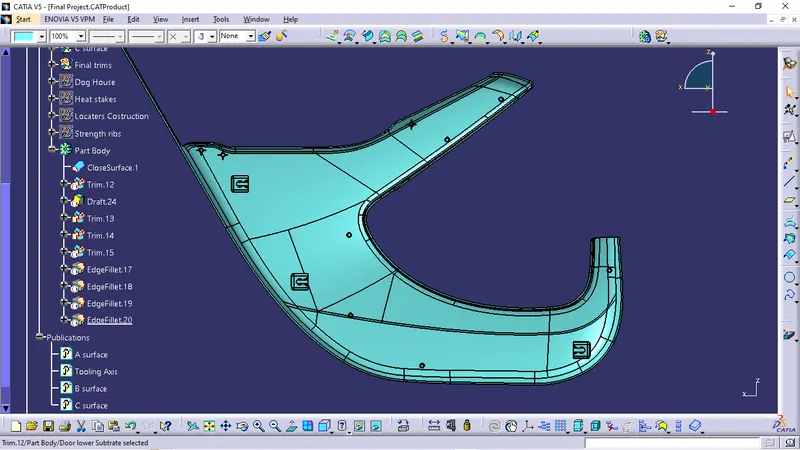
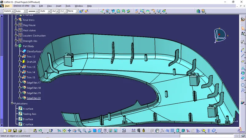
Attachment Features :
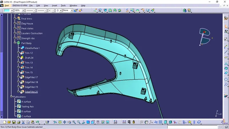
- This features are required to attach one part to another part.
- Like Flanges,Heat stakes,Screw Bosses and Dog houses.
- This is done by following the master section and some are by own.
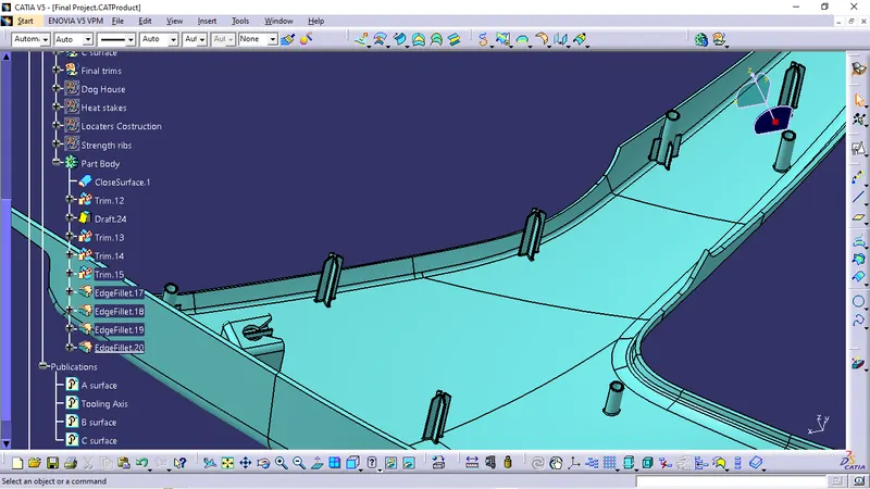
Engineering Features :
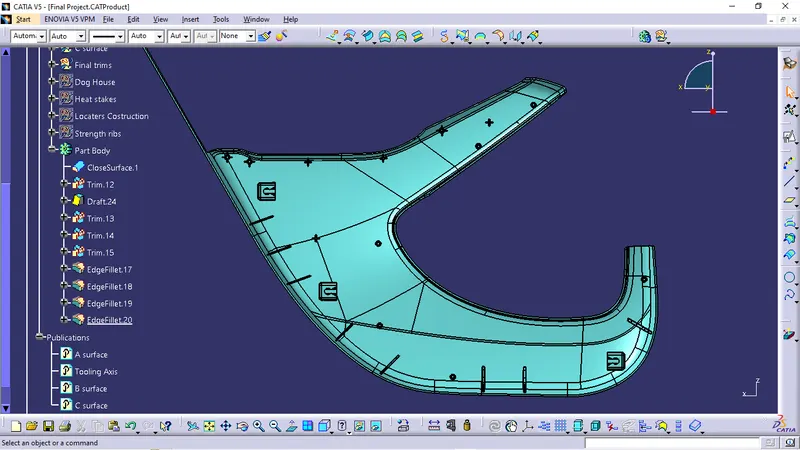
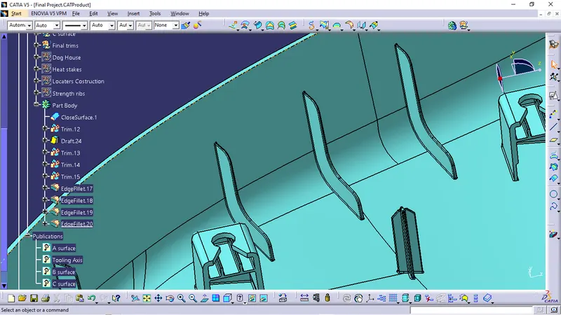
- The engineering features are used to strengthen the part and to produce the part without any deviations.
- By following the standard engineering features the part can be produced without any issues.
- Like Ribs,Locaters etc.,
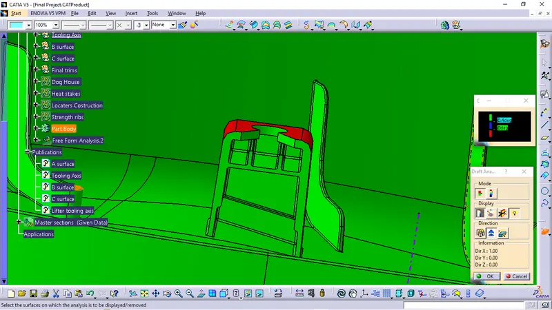
Draft Analysis :
- Draft analysis done to part body along tooling axis and side core tooling axis with required draft angle. The results are shown below.
Main tooling axis Draft analysis :
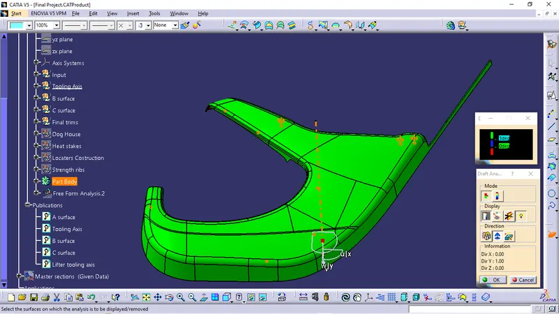
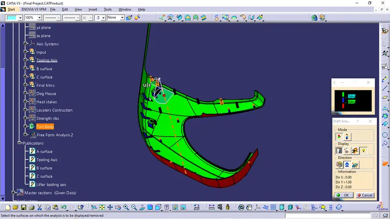
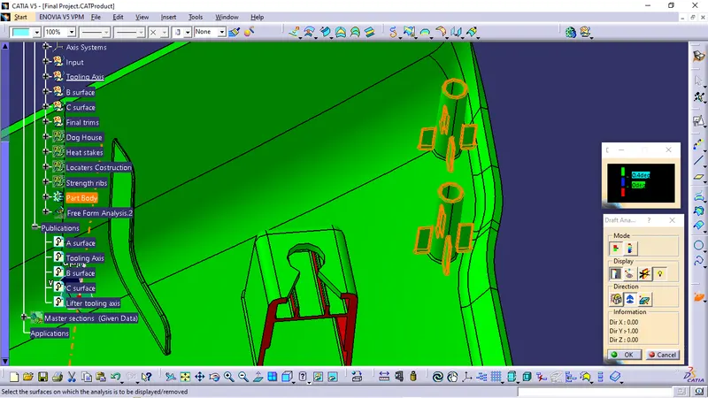
- Some faces are not clearing with main tooling axis due to improper Class A surface.
- Some are showing in blue which means it is below 3degree and above 0degree.
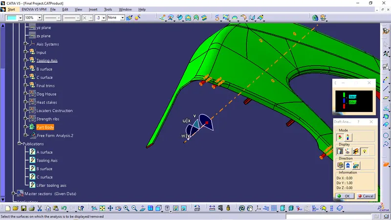
Side Core Tooling axis :
- The Violet center line is Side core tooling axis.
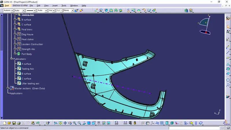
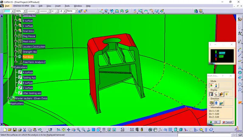
For more details on draft analysis a proper PPT is submitted.
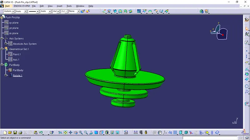
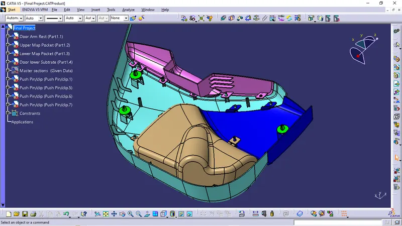
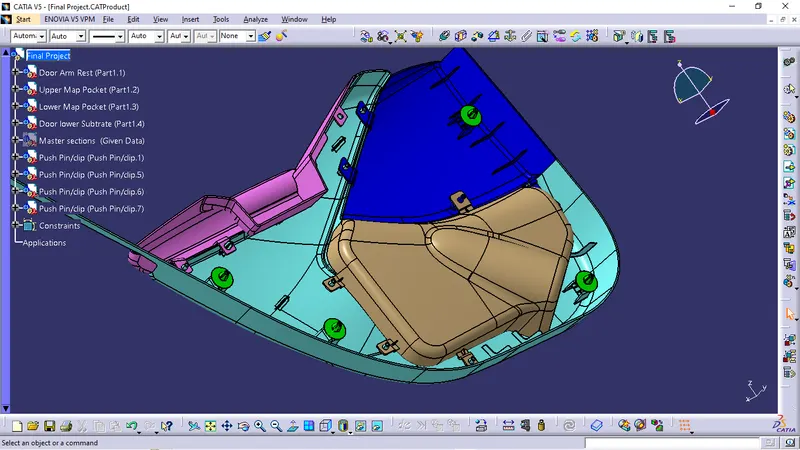
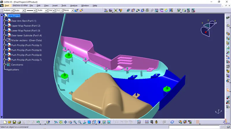
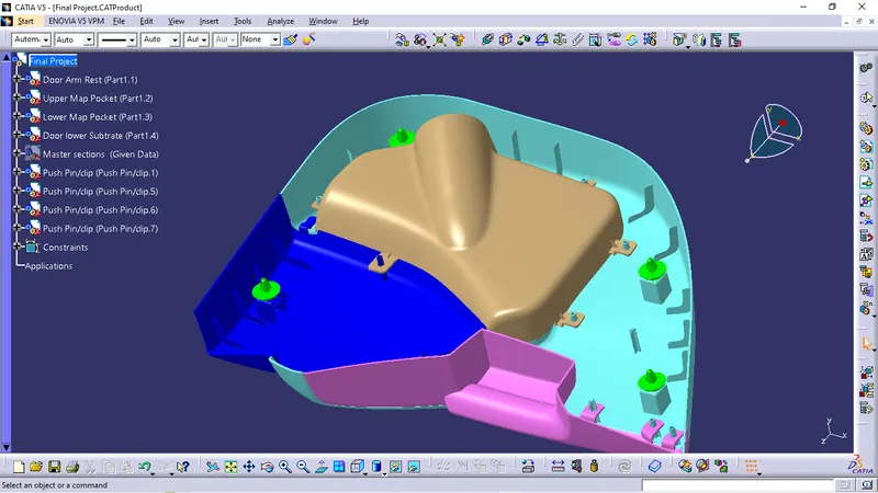
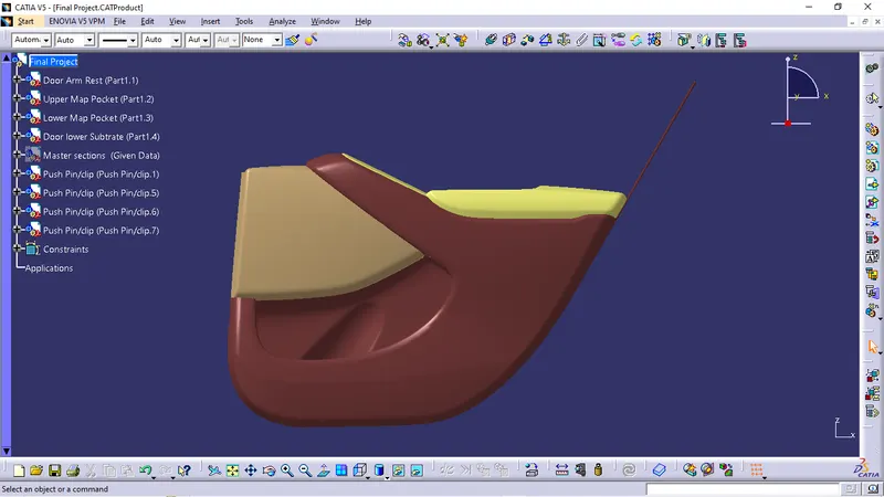
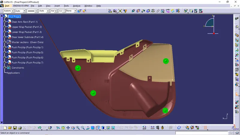
Push Pin Clip :
- This push pin clips are used to asemble the outer sheet metal of door and inner trim panel.
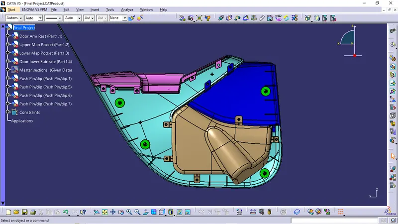
- these are placed on dog houses as shown below.
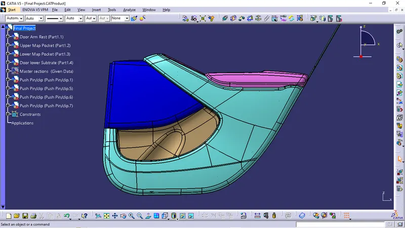
Door Trim Panel Full Assembly :
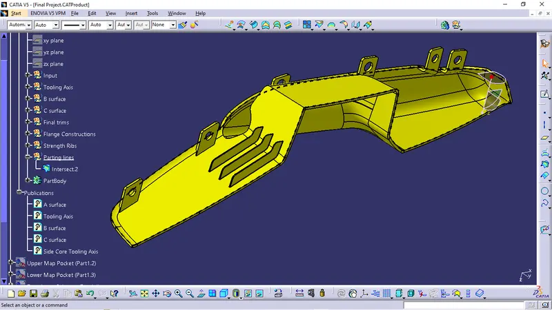
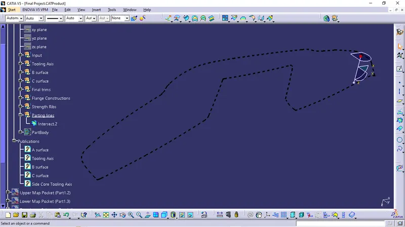
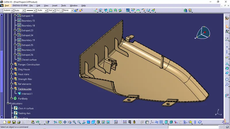
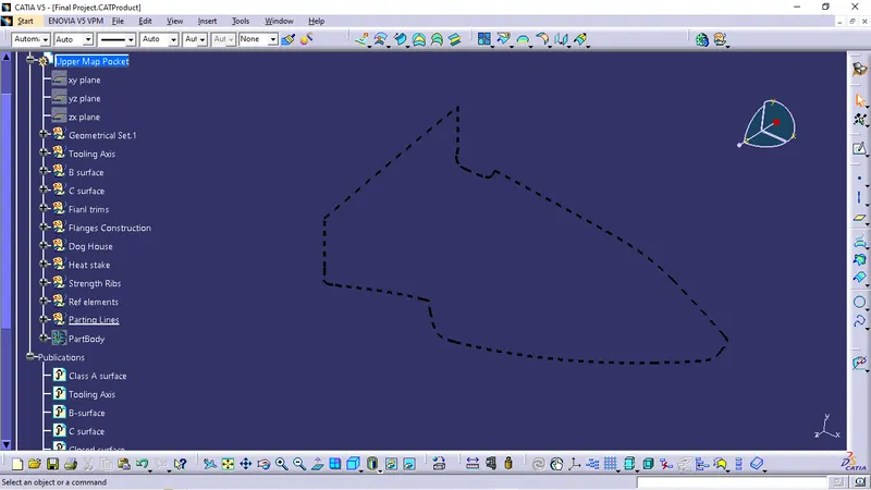
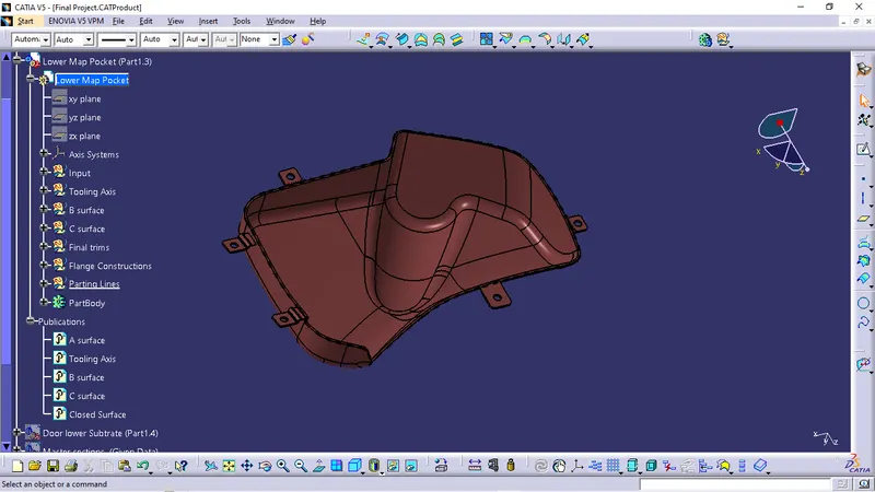
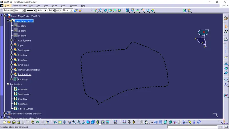
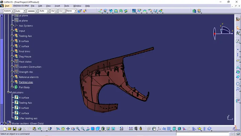
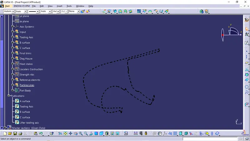
Parting Lines :
Door Arm Rest :
Upper Map Pocket :
Lower Map Pocket :.
Lower Subtrate :
CONCLUSION :
- Design of door trim panel with all engineering and attachment features are created.
- Draft analysis of each part done individually.
- Parting lines done for every part indivdually.
- Assembling of push pin clips also done.