Week 11 - Final project
AIM
To design and development of vehicle interior door trim using Catia V5 with given class A surface along with Master section. Also create the side attachment features as per design rules.
Introduction
The door panel is the interface between the interior of the car and inner working of the door. Generally, the door panel is divided in to parts for easy designing like arm rest, map pocket, lower substrate. These require one of the toughest requirements among the interior parts of the car. This should be designed to with stand the load while being less than 2mm in thickness and also to protect the occupants during collisions.
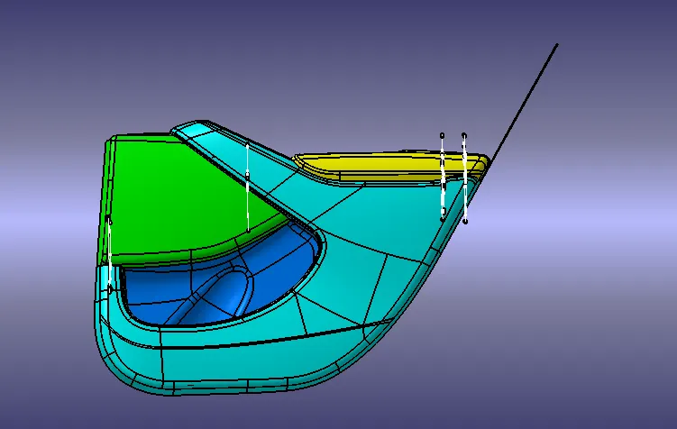
Method followed in creation of the plastic new product design are
- Tooling axis creation
- Class B surface creation
- Class C surface creation
- Closed body creation
- Draft analysis
Procedure of part creation
Interior door trim consists of four components.
1.Lower substrate
2.Upper substrate
3.Map pocket
4.Door arm rest
Class-A Surface
A-class surfaces are those aesthetic/ free form surfaces, which are visible to us (interior/exterior), having an optimal aesthetic shape and high surface quality. Mathematically class-A surfaces are those surfaces which are curvature continuous while providing the simplest mathematical representation needed for the desired shape/form and does not have any undesirable waviness. Products are not only designed considering the functionality but special consideration is given to its form/aesthetics which can bring a desire in one’s mind to own that product. This is only possible with high-class finish and good forms. This is the reason why in design industries Class-A surfaces are given more importance. In automotive design, a class-A surface is any of a set of freeform surfaces of high efficiency and quality.
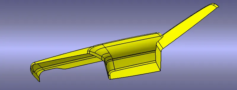
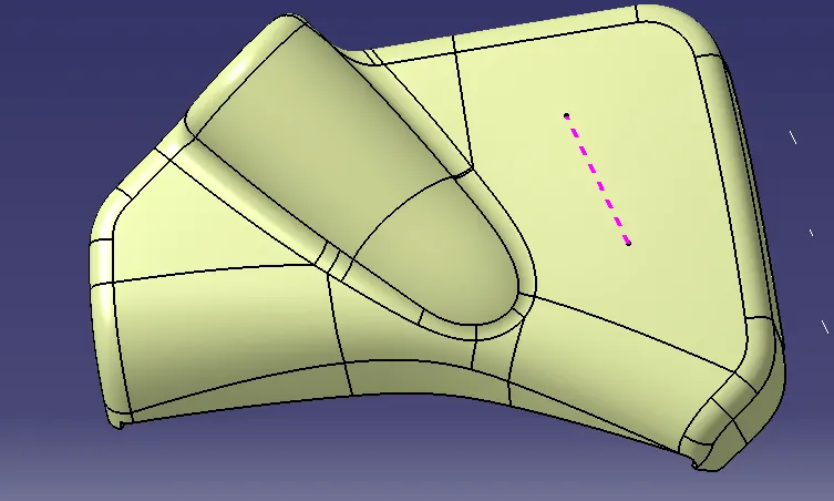
Door arm rest
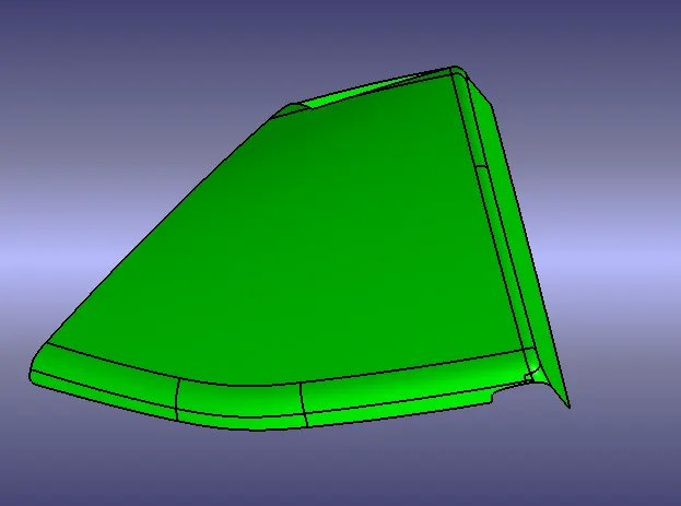
Map pocket
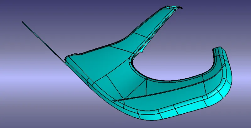
LOWER SUBSTRATE
BOTTOL HOLDER
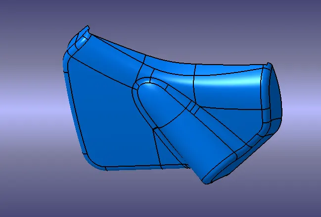
Tooling axis
Tooling axis is nothing but the direction in which the core and cavity opens and closes. Design engineer works on it to analyse the Class A surface and finds out the best possible tooling direction keeping in mind all the draft angle is with respect to the tooling axis so that the component can be easily ejected from the moulds.
Conditions to check tooling axis
- Check all the boundary whether it has connected or not.
- Check the model visually & choose the best tooling direction which should be easy for draft.
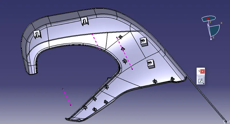
Create tooling axis to the lower substrate
Whether checking thre part simple way to draw line in axis direction.
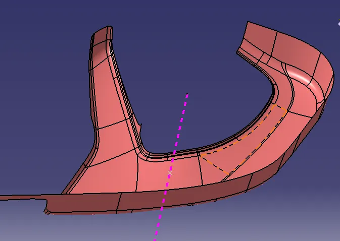
Tooling axis creation for Door rest arm
Whether analysis the door rest arm class a surface some of part sould be in inverse direction so create tooling axis in two diraction.
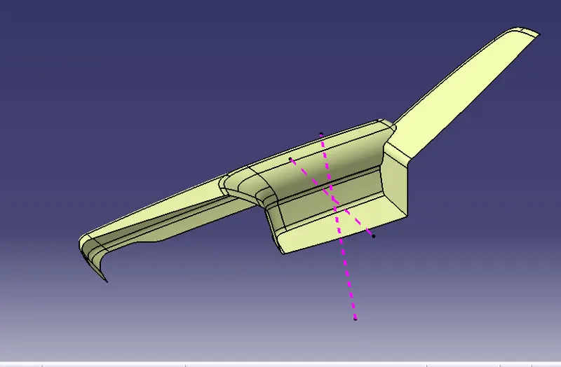
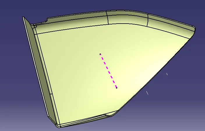
Tooling axis creation for map pocket
Map pocket tooling axis created to the axis direction.
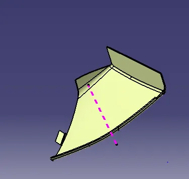
Tooling Axis creation for Bottle holder
same as well as for map pocket axis direction
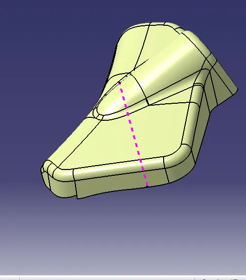
CREATION OF CLASS B SURFACE
- Insert a new gemeotrical set.Measure the value of thickness in master section.The value is 2.5mm
- Offset the class A surface to 2.5mm.
- Check all the sub elements are formed if not try to fix it locally
Creation Bottle holder B surface
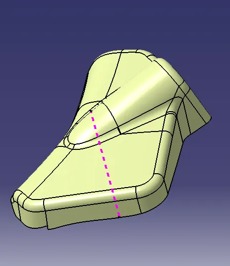
Creation of b surface for map pocket
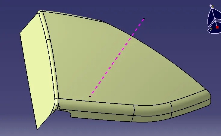
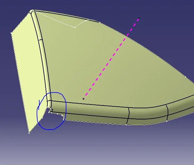
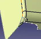
To work with locally multi section solid then join the the surfaces
Creation of B surface of lower substrate
Offset to the A surface for 2.5 mm
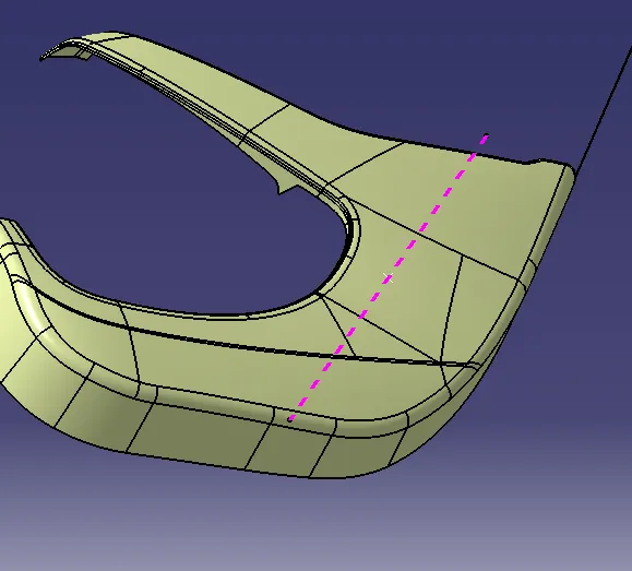
B surface creation for Door arm rest
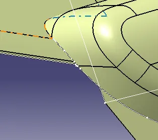
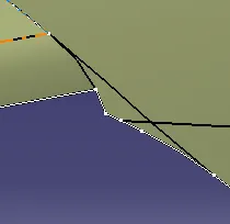
when analysing class surface some portion are small cap found to increase the merging distane to avoid the gap also spilt the shrape edge to class a surface
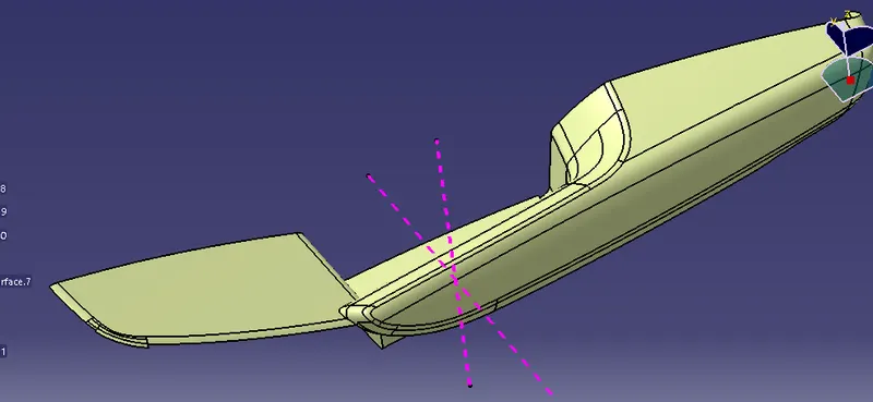
CREATION OF CLASS C SURFACE
- Analyse the class A once where the sweep is easier to create towards tooling direction
- Create a boundary using limitation points whereever possible for sweep
- to create a sweep with reference to surface of input
C surface for Door arm rest
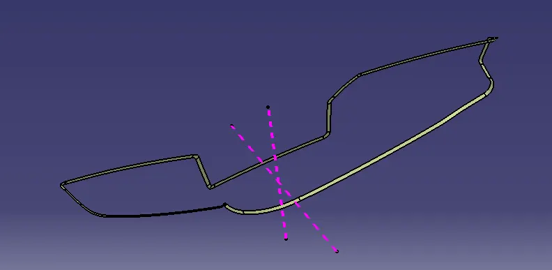
Creation Of C surface for Lower substrate
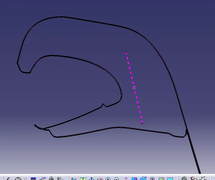
C surface for Map pocket
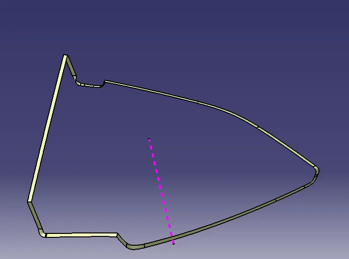
C surface for Bottle Holder
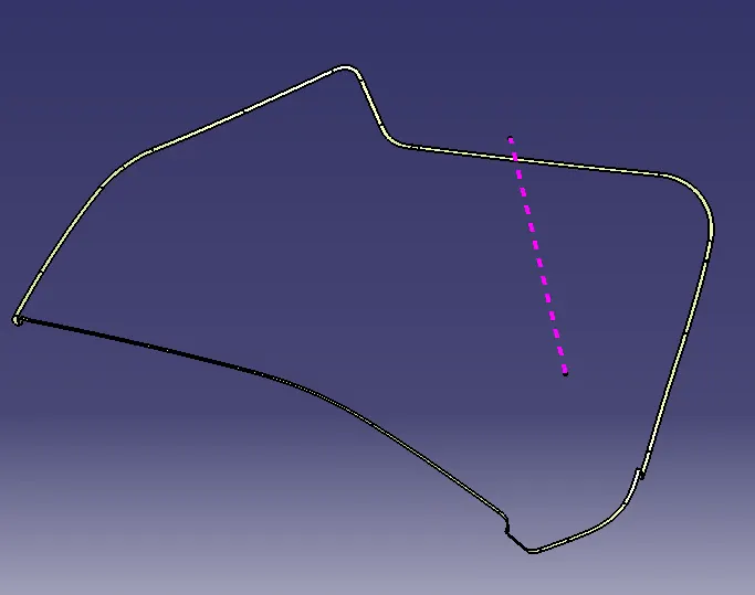
Close surface
After Creation of B and C surface then join A AND C surface trim the B surface then check whether any boundry found in closed surface
After join and trimining go to part workbance to close surface command add material
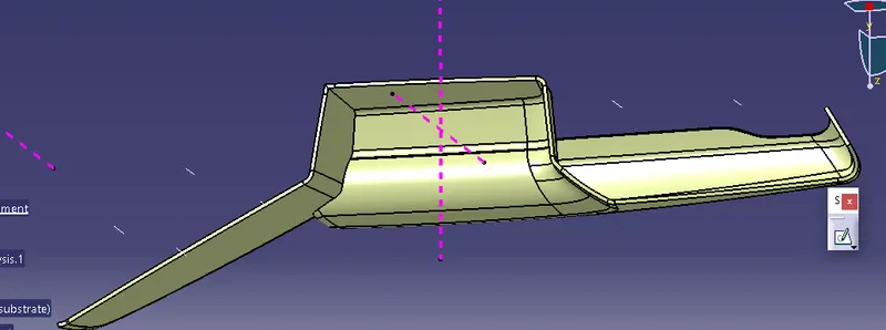
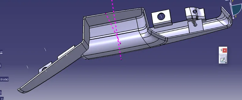
Lower substrate
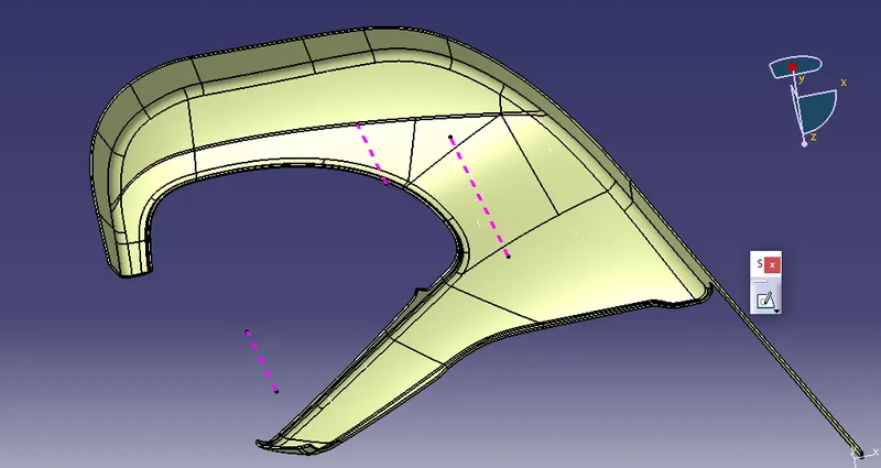
Map pocket
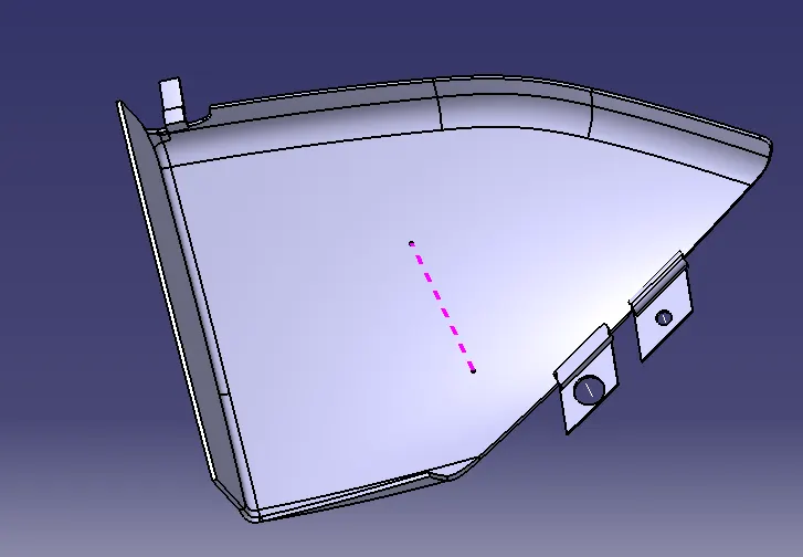
Bottle Holder
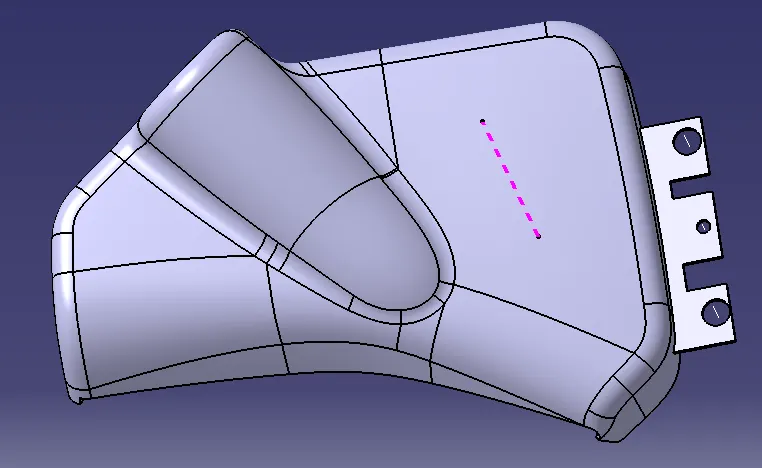
Creation of Attachment Feature to the Door Trim B surface
Dog house creation
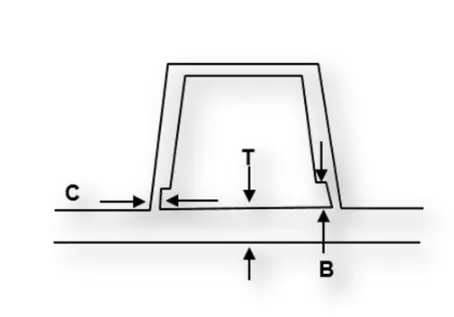
Dog house is an engineering feature used in plastic trim design. Dog houses are used as supporting feature. Sometimes other engineering features like snaps; locators etc. are mounded on them to increase their strength. Dog houses are subjected to draft analysis to prevent breakage of the component during ejection from mould cavity. Dog house and other engineering components are built on B-surface
Dog house rule
B=4mm
t=2.5mm
C=0.4 * t=1mm
- Extract the sweep and offset to b=4mm and c=1mm on all directions like the below
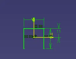
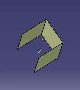
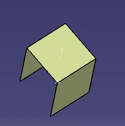
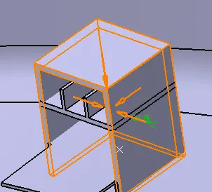
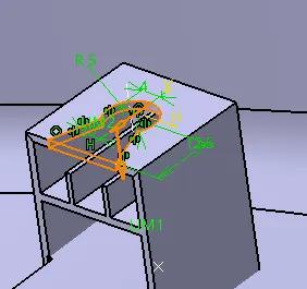
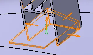
After creating dog house to perform drafting 0.5 deg to all surface and fillet to share edge 0.3 mm
HEAT STAKES
Heatstakes is known as thermoplastic staking is the process of joining two dissimilar metals together
- Extract the surface that we going to create heat stake
- Use positiioned sketch and draw a heat stakes sketch
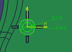
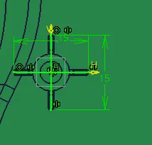
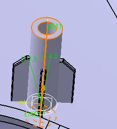
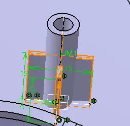
Then chamfer 3mm to the ribs and perform a drafting 0.5 mm also uniontrim to screw boss
Locators
Locator are control the part allinment
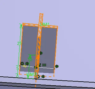
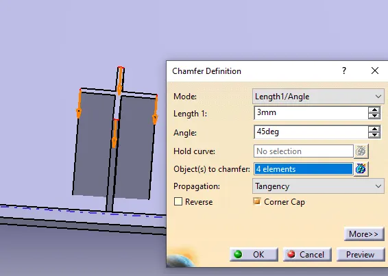
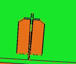
Then drafting in 0.5 mm and fillet to all faces in.3 mm
After creating locator and heat stake to union trim with lower substrate
FLANGE
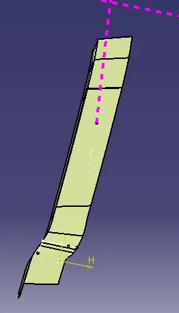
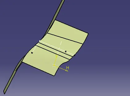
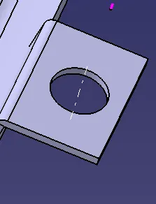
Create a flange for attachment of heatstakes and locators at lower substrate
Draft analysis
his type of analysis is performed based on colour ranges identifying zones on the analysed component where the deviation from the draft direction at any point, corresponds to specified values. This rule of thumb applies to parts with mold depths of up to 2 inches. At this size, draft as low as 1½ degrees will allow for an easy, non-damaging release from the mold when the expected shrinkage of the thermoplastic material occurs.
It’s also important to remember that draft angles are just one component of an effectively designed injection molded piece. Design for manufacture is one of the easiest ways to improve the quality and efficiency of your injection molding process, and it never hurts to stay up to speed on all injection molding best practices.
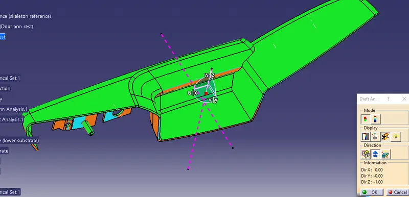
Once compass is locked in the axis, directly click on the surface it will appear quality of draft surface whether, it is pass or failed. Here the draft angle is given as 3 degree. Hence we achieved green colour on top surface. Hence it accepts the draft angle for the surface, so we build good quality component.
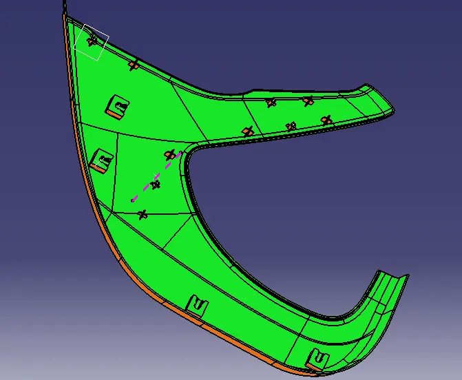
Now we check colour variant scale to ensure the maximum and minimum area draft angle is achieved by displaying by green, red and blue colour respectively. If the surface appears red in colour while analysing it is not accepted.
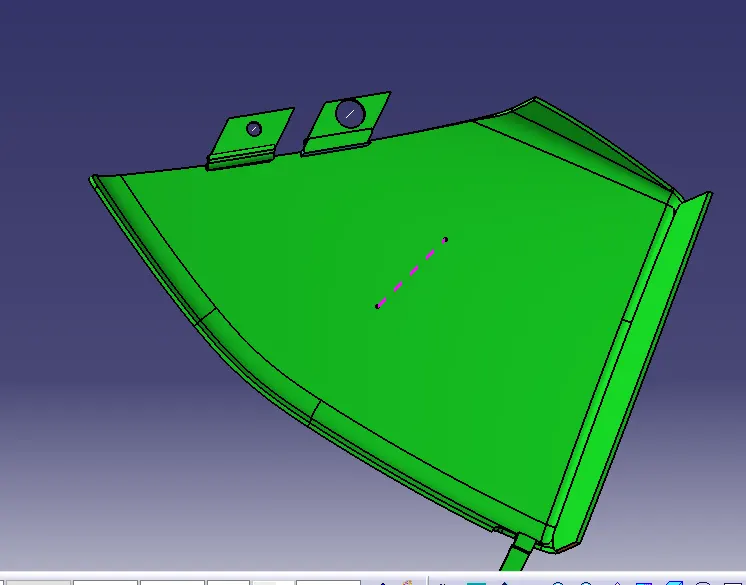
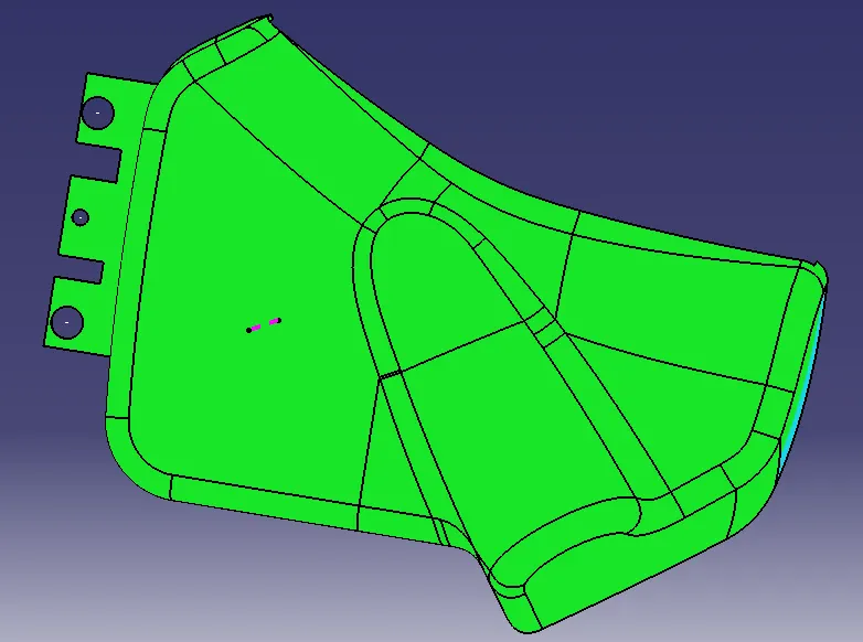
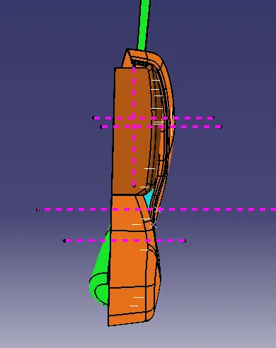
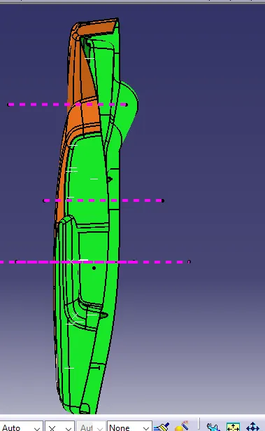
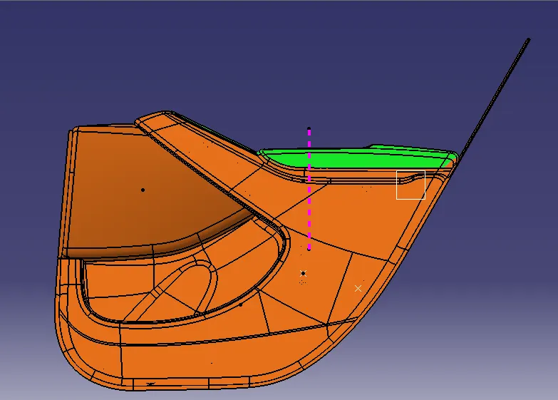
Some views of door panel
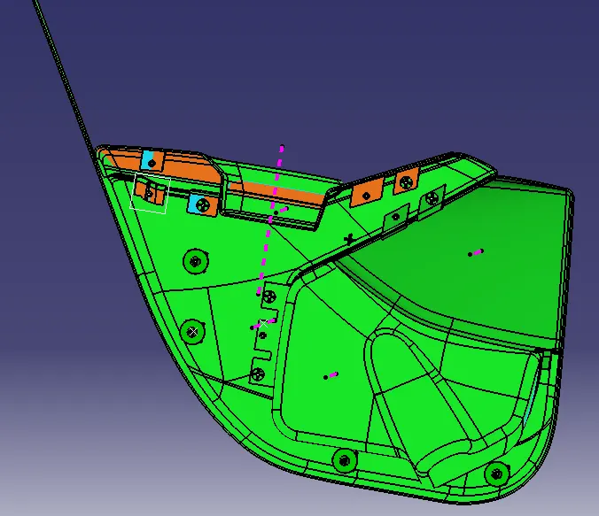
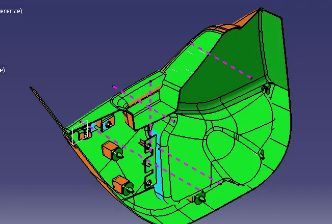
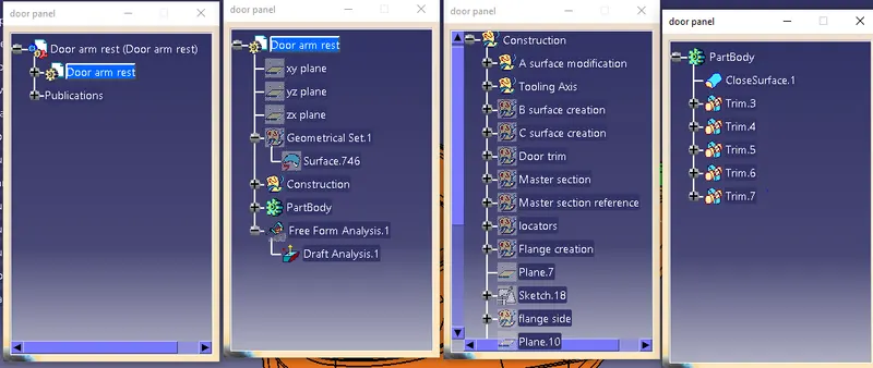
Model tree
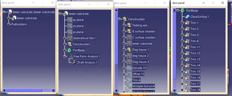
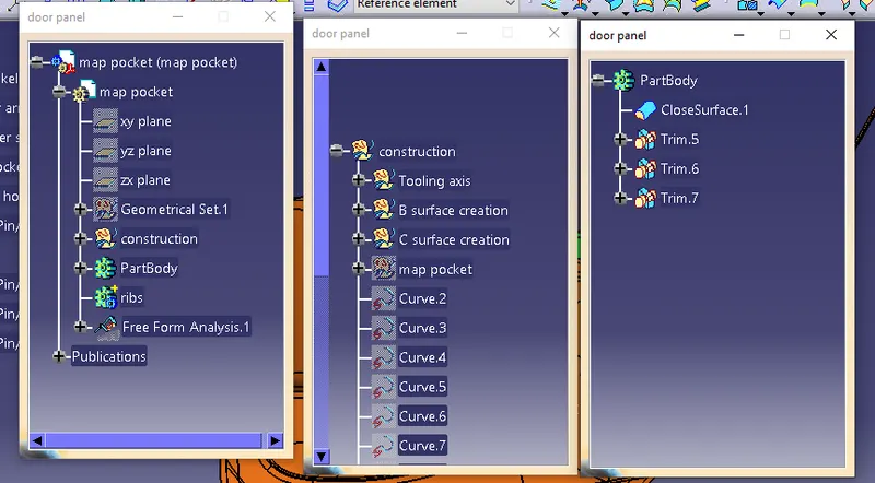
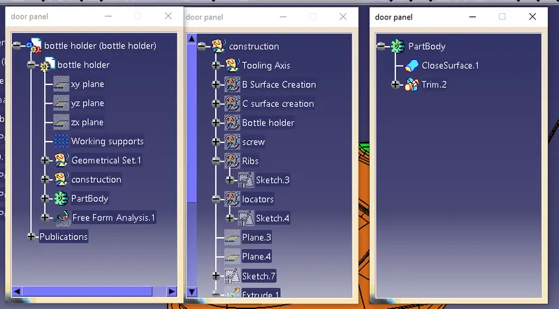
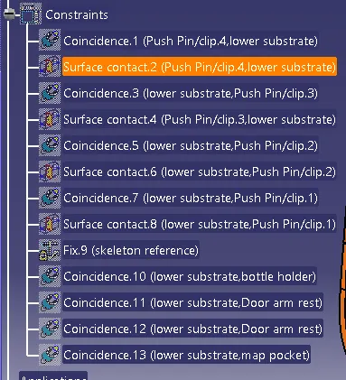
Conclusion:
Creation of the car interior door trim is designed using the given class A surface as the input and Class B and C surface created with the help of Class A surface. By using the given master section attachment features I.e. Heat stakes, Flanges, Dog House and Push Clips are created using the design rules. The draft analysis has been performed to analysis the draft of the component to manufacture easily applying draft to the surface by 3 degree and 0.5 degree to the attachment features.