Week 11 - Final project
AIM: To design the car door inner panel with reference to given Class-A surface by using given mastersection, creating attachment features and performing draft analysis to check the manufacturing feasibility of the component by using software CATIA V5.
Objective: The project deals with the explanation of method followed to develop door trim inner panel. In this with the given Class-A surface, Class-B surface and Class-C surface were created along with the tooling axis. Other attachment features were also created for assembly of the different components of door trim.
Methodology:
The methodology of the project is explained here:
1. Class-A suface was extracted from the given surface.
2. Tooling Axis were created of the individual component.
3. Class-B and Class-C surface were created with the OEM guidelines.
4. Formed Solid body from the closed surface.
5. Engineering features were created for attachment.
6. Draft analyses of each component was performed to check the manufacturing feasibility.
Introduction:
The inner door panel is an aesthetic and functional component in a car, it is the interface between the car interior and the inner working of door. Inner door panel usually consists of armrest, map pocket, bottle holder, handle bar, other switches, upper and lower substrate, storage compartments, convenience (puddle) lights and locking mechanism. Nowdays door panel is made of plastic material like polypropylene, ABS etc. which helps in making lightweight and complicated shapes of door panels.
The manufacuring Process of plastic door panel is called Injection molding. In this manufacturing process the heated molten plastic material is injected into the mould between core and cavity and cooled down to form a solid plastic component.
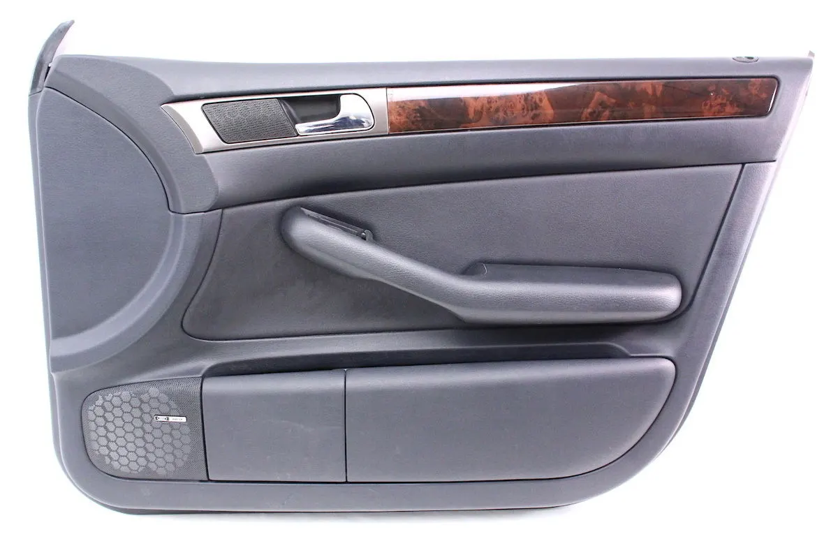
PROCEDURE
Given CLASS-A surface with Mastersection
Components included in door panel
Map pocket
Bottle holder
Lower substrate
Armrest
Map Pocket
Class-A surface of Map Pocket
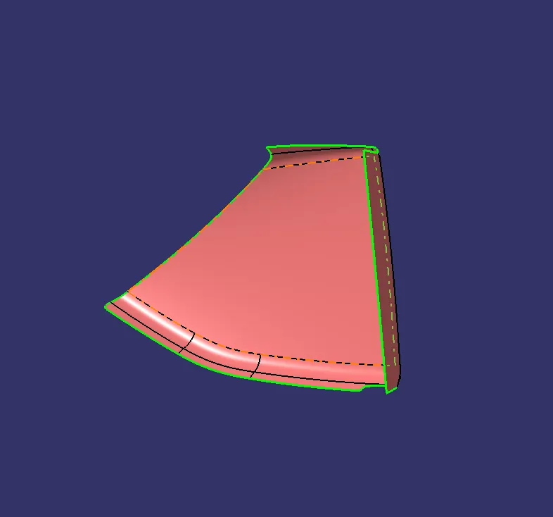
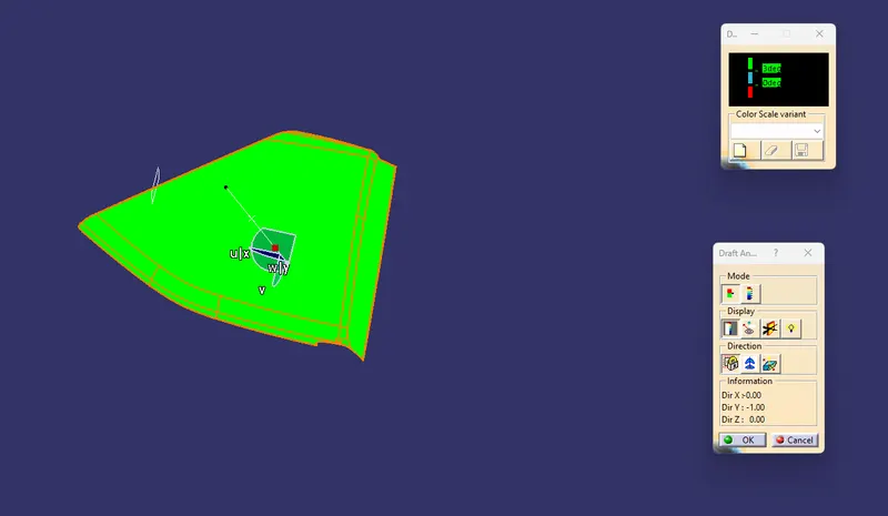
Here, to check the Class-A surface manufacturing feasibiliy as a plastic product Draft analysis was performed on it at 3 degrees.
Draft Analysis: It is performed to check the manufacturing feasibilty of a component or part, in plastic manufacturing process we generally provide 3 degrees draft and 0.5 degree draft in critical conditions. To perform draft analysis first tooling axis was created by taking a point on surface and line was created in the direction in which part will form easily with provided draft.
Map Pocket Class-A surface Draft analysis along Tooling Direction
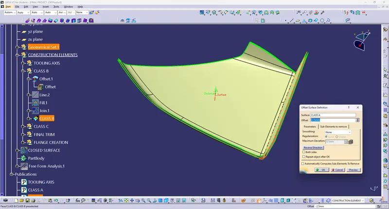
Map Pocket Class-B Surface Creation
To create Class-B surface of map pocket, class-A surface was offset at a distance of 2.5mm
Map Pocket Class-C Surface Creation
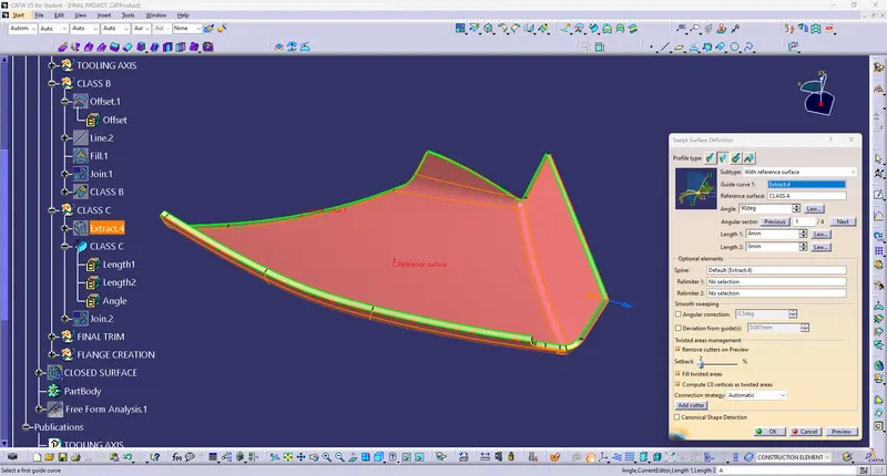
Class-C surface was swept from the boundary of the Class-A surface. Class-C surface was swept with 3 degrees along tooling direction.
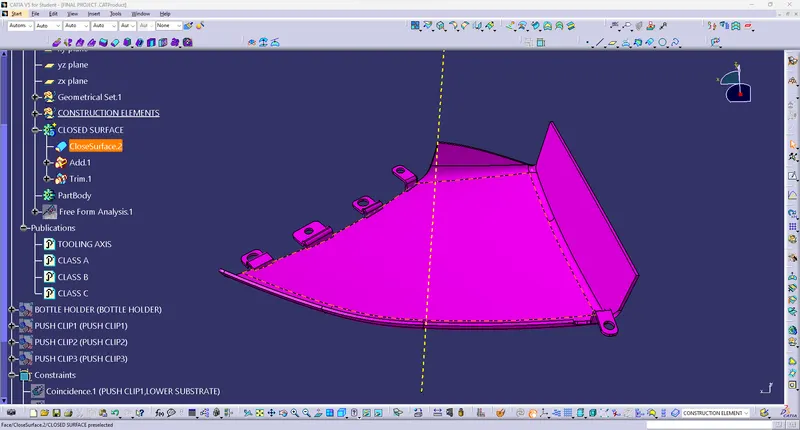
After creating Class-B and Class- C surfaces, both surfaces wer timmed with Class- A surface to form a closed surface of map pocket.
Map Pocket Closed surface-
Closed surface draft analysis for analyzing Class-B and Class-C surface
Then Map Pocket clo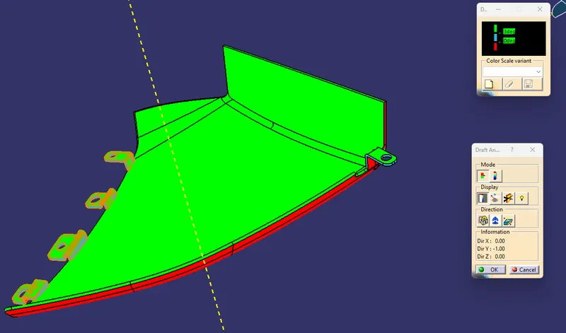 sed surface was converted as a solid body with the use of feature called closed body in part workbench. Other engineering features like Flanges, Doghouse, created on the closed body of map pocket with consideration of 0.5 degree draft for easy manufacturing of the component.
Draft Analysis of attachment features at 0.5 degree.
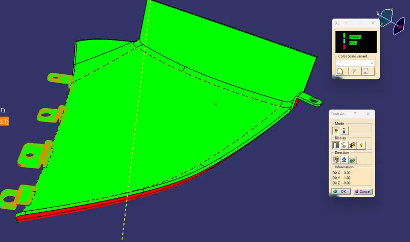
BOTTLE HOLDER
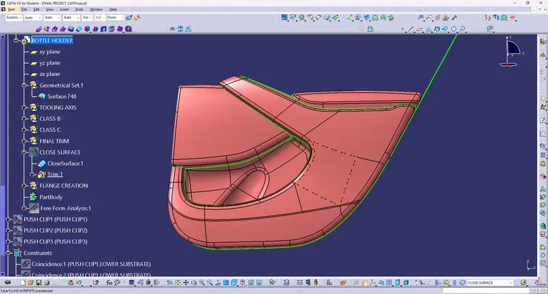
Class-A Surface of bottle holder
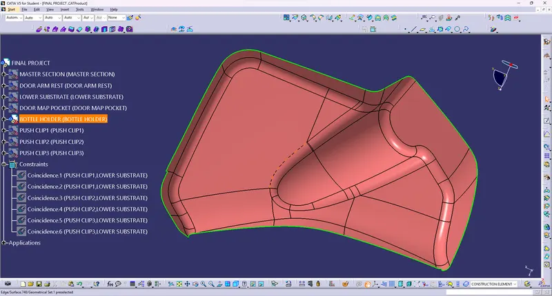
Draft Analysis performed on Class-A surface along Tooling Direction
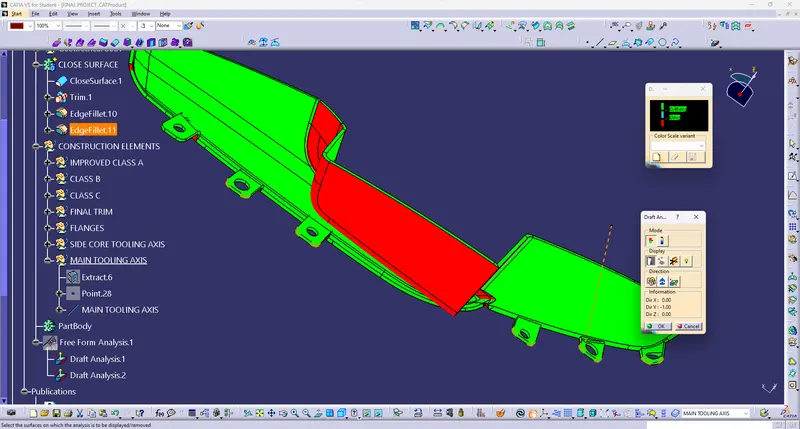
In this part one tooling axis was not able to clear the draft of the component, so side sore axis was provided to form the component. This issue must be discussed with other designers like NPD CAD team or Class-A modeler because using side core can be expensive way to manufacture a plastic component. So, if it possible to make changes in design, should be done which helps in easy and low cost manufacturing of component.
Main Tooling Axis of Bottle holder
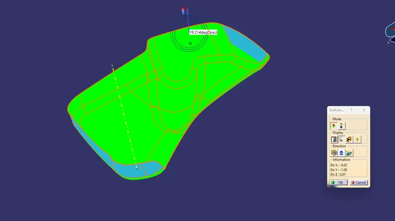
SOME AREA IS NOT CLEARED-
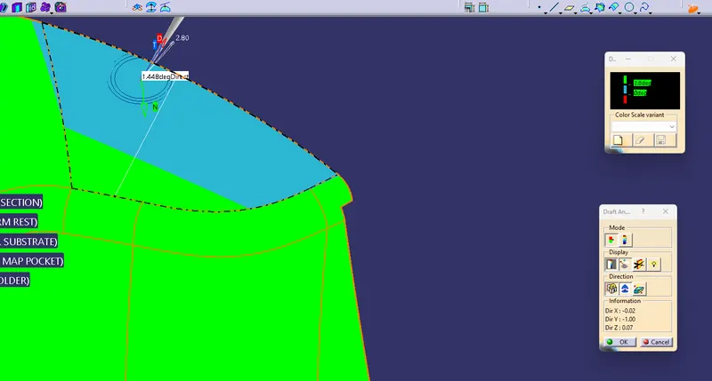
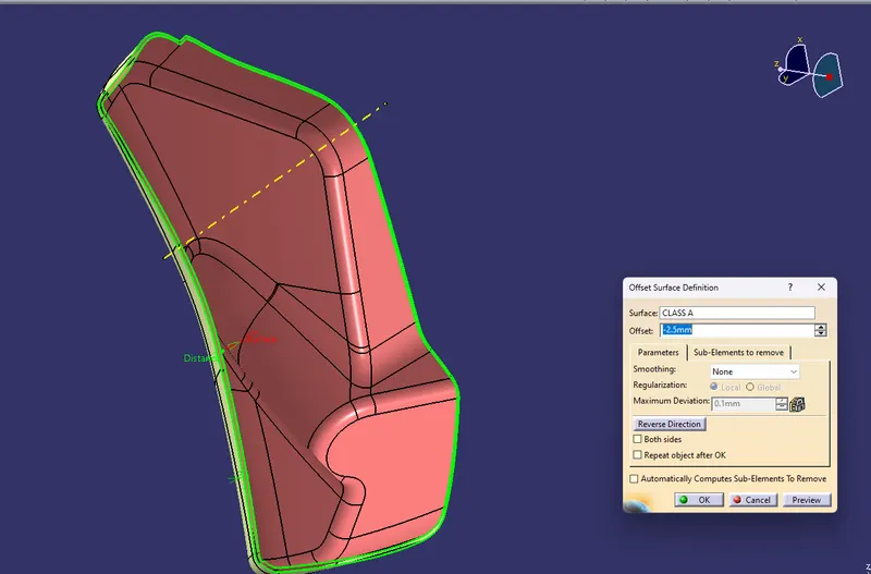
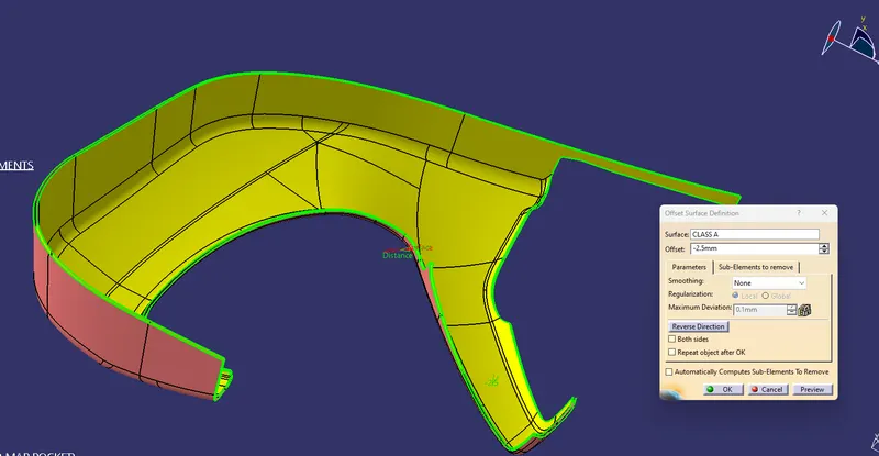
Class-B surface created by offset of 2.5 mm of Class-A
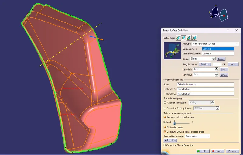
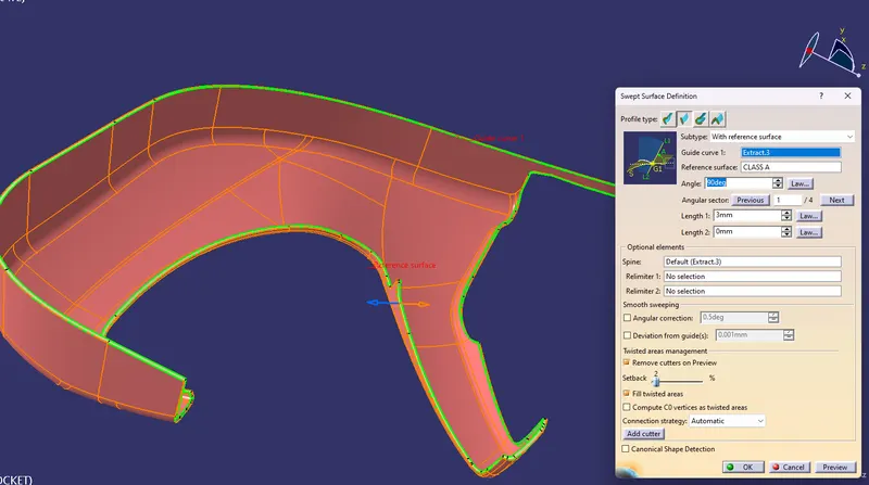
Class-C surface was swept from the Class-A surface At 90 deg
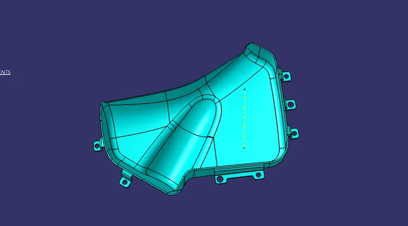
Closed Surface of bottle holder which is formed by trimming the Class-A, Class-B and Class-C surface.
Draft Analysis for Close Surface
Main Tooling Axis Draft Analysis
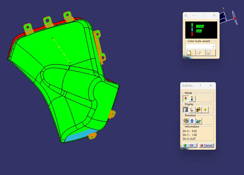
Draft Analysis of attachments features with 0.5 degree draft
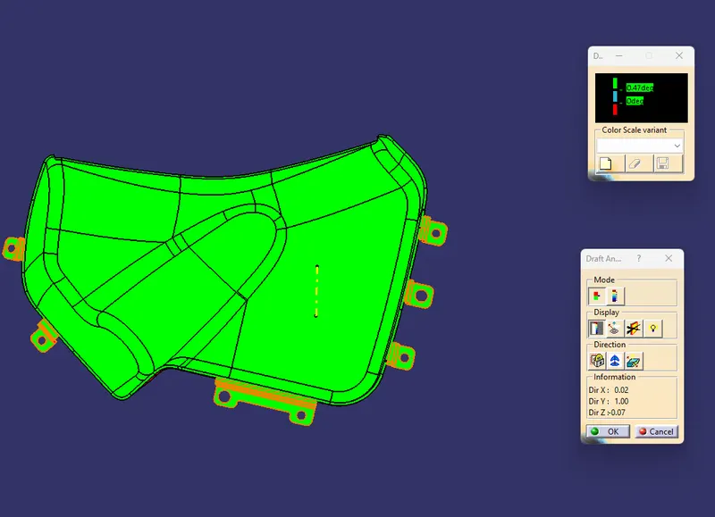
LOWER SUBSTRATE
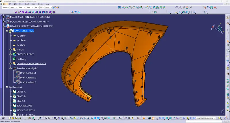
Class-A surface of Lower substrate
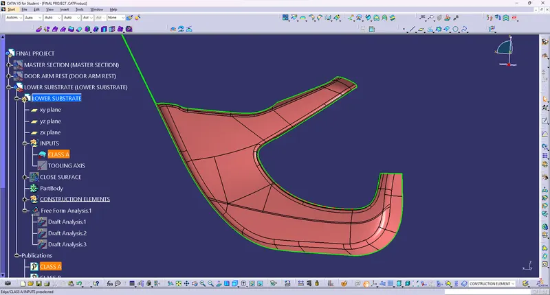
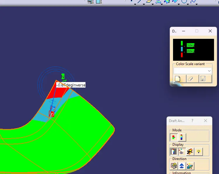
Draft Analysis on Class-A surface with 3 degrees along Tooling Direction
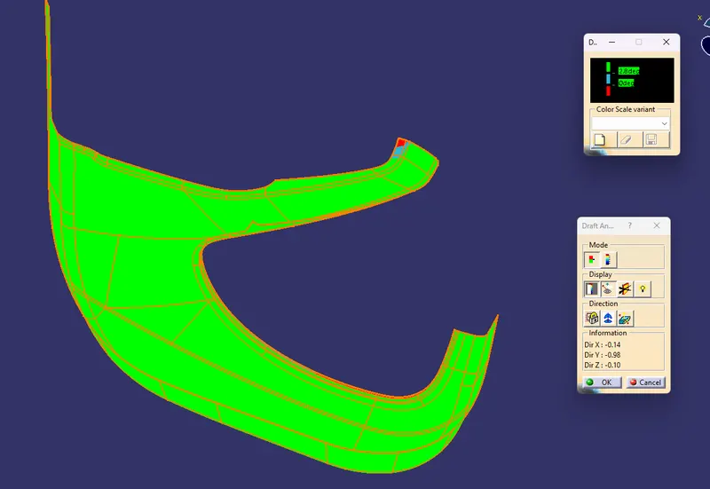
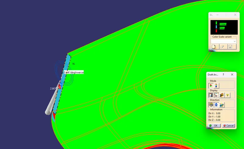
Some areas n ot cleared
Class-B surface offset at 2.5 mm from class-A
Class-C surface swept from Class-A boundary with 90deg surface
Lower substrate Closed surface
Draft Aalysis of Close surface
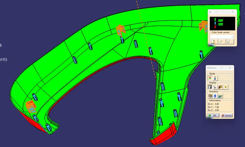
Lower Substrate Closed body with attachments features like heat stakes, Locators, Doghouse, with 0.5 degrees draft
Draft Analysis of attachment features
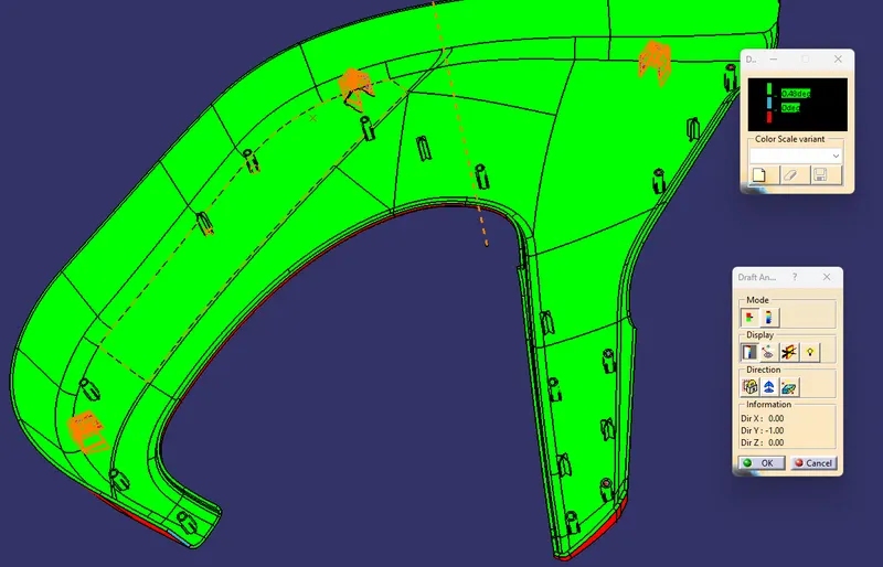
Draft Analysis of DogHouse Tooling Axis
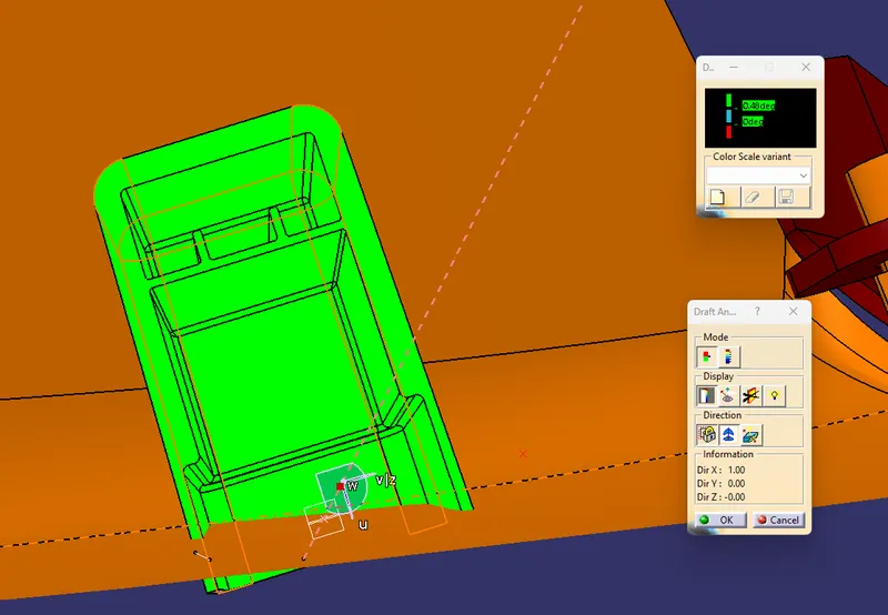
Attachment features
DOGHOUSE- Doghouse is an engineering feature used in the plastic trim design which helps to remove sink marks formed on Class-A surface while creating attachment feature on Class-B surface. Doghouse is a supporting feature, other features like locators, heat stakes, pushpins are mounted on top of doghouse for fixing and assembly purpose. Doghouses are subjected to draft analysis to prevent breakage of the component during ejection from the mould.
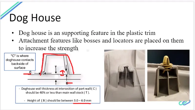
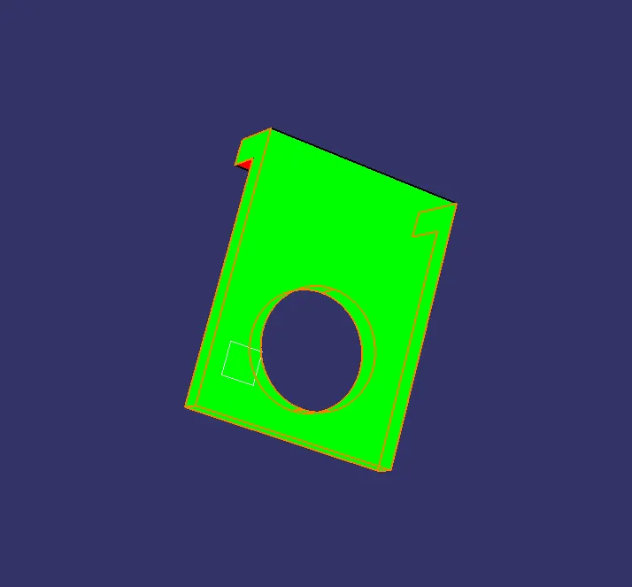
Flanges- Flanges are the joining features that help to assemble different components. The mastersection was used to make flanges. After creating one flange axis to axis sytem was used to translate the flanges. The draft of 0.5 is given to the flanges. The gap between flanges should be 60-100 mm. Boolean operations were used to add attachment features into closed body.
DRAFT ON FLANGE
PUSH PINS- Push pins are used for joining one component to another . These are basically attached to the doghouse.
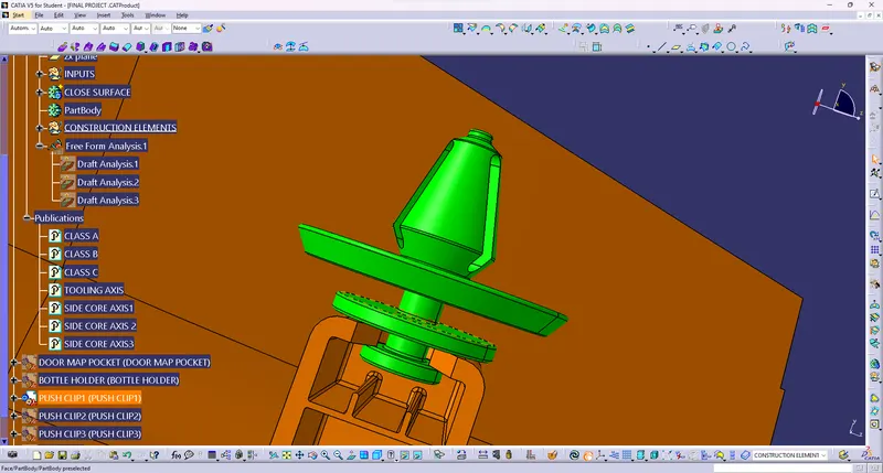
HEAT STAKES- Heat stakes also known as thermoplastic staking, it is process of joining two dissimilar materials together. In heat staking, local heating and cooling is used to raise the temperature of plastic components and allow plastic reforming to be carried out. This reforming can be used in a wide variety of applications.
Applications range from staking plastic bosses for assembly of car door panels to joining PCBs to plastic housings. Banefits of his technique includes; no vibration damage, no particulates, the ability to stake metalized coated application and the capability to stake in difficult to access or restricted areas.
The progressive melting of plastic under continuous pressure forms the head. When staking the right combinations of heat and pressure for the applications is critical.
The advantages of heat staking are as follows:
- Simplications of the machinery
- Reduced cost of machinery.
- Multiple fastening point.
- Allows higher density of welds compared to hot air, cold form or ultrasonic welding.
Locators- Locators provide easy alignment to the parts which are mating with each other.
The design rules of ribs
- Rib thickness should be 0.4 times of thickness of the part.
- The walls of rib should be drafted with 0.5 degrees draft.
- Top height of ribs should be at least 5 times part thickness
- Thickness of rib at tip should be equal or less than 0.75mm.
- Maximun fillet vale should be 0.25mm Radius..
ARMREST
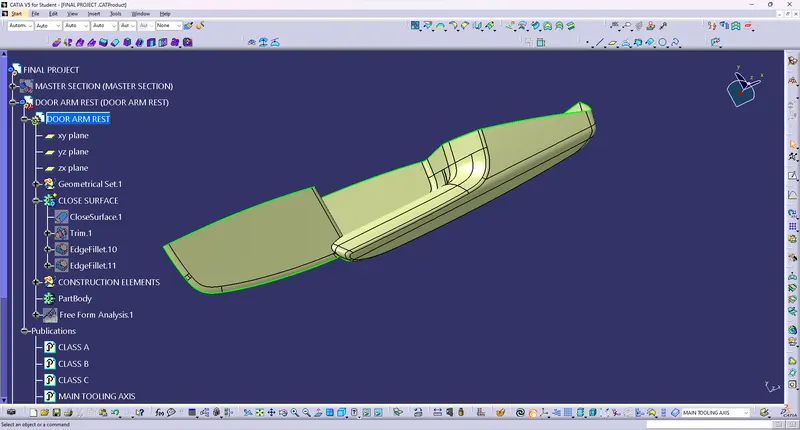
Armrest was not able to clear in a single tooling direction so it was splitted into two parts for easy manufacturing.
Draft Analysis of Class-A surface
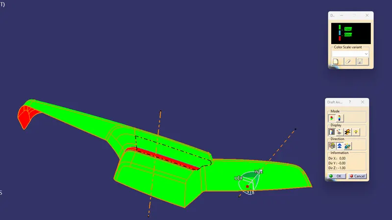
SIDE CORE DRAFT
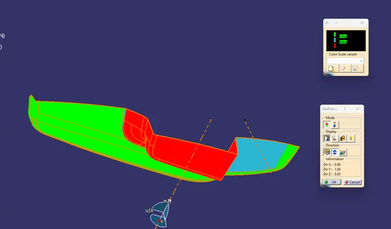
Class-B surface offset at 2.5 mm from Class-A
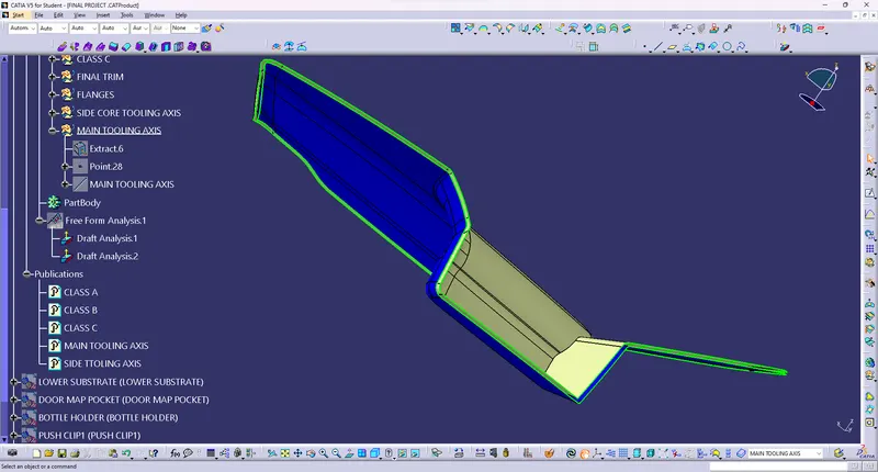
Class-C swept from Surface at 90 deg
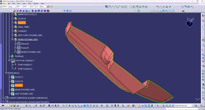
Armrest Closed Surface
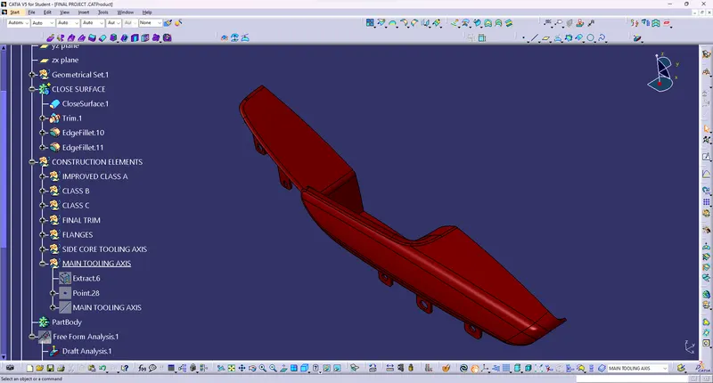
Draft Analysis of Armrest Closed surface
Draft Analysis Of attachment features
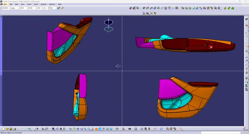
Final Door Trim Engineering Features Different View
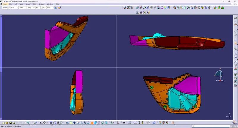
MASTER SECTION MATCH
MASTER SECTION FOR ARM AND LOWER SUBSTRATE-
here for matching the master section there is soft touch material in master section , so i offseted the class a to 1mm
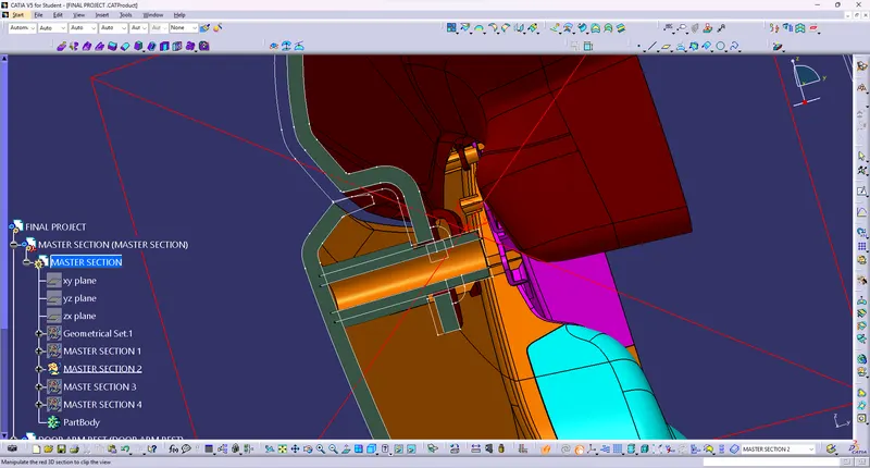
MASTER SECTION FOR MAP POCKET AND LOWER SUBSTRATE
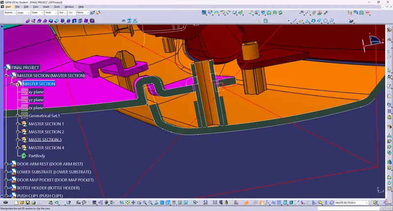
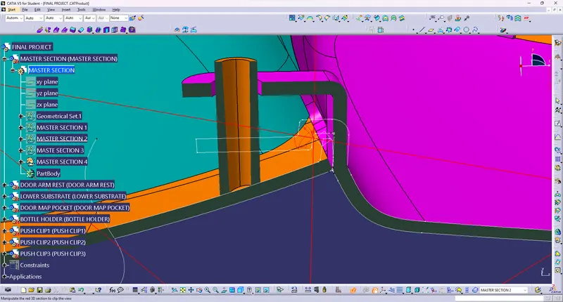
MASTER SECTION FOR MAP POCKET AND LOWER SUBSTRATE2
Here i made mistake created the the flange as per the hieght didnt refers the master section
Conclusion
Door Trim was made with OEM guidelines using Part Workbench and Generative Shape Design Workbench using CATIA V5.