Week 11 - Final project
AIM - By following the design rules and OEM standards create the door trim panel of CAD model considering the inputs given to me
ABSTRACT - The project deals with the explanation of steps and procedures followed while developing the Door Trim Panel of a car using CATIA V5. Using the class A surface, I was able to create the tooling axis, class B surface, class C surface, and after forming the solid body from that I was able to create the flanges and the B side features such as Heat stakes, four-way locators, Dog house, push pins, etc. And finally, the draft analysis is also done on the components to check the manufacturability of the components.
INTRODUCTION - The door panel will usually match the rest of the vehicle's interior. Door panels were formerly made of cardboard with an upholstered interior finish of vinyl, leather, cloth, carpet, or other materials for the decorative trim. Modern cars typically have door cards made of plastic, most often using injection molding, as well as incorporating other decorative materials.
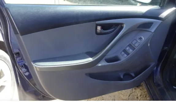
The steps that I followed for this project is mentioned below:
1) Extracting the class A surface from the input which is given
2) Class A surface check and performed draft analysis
3) Tooling axis creation
4) Creation of class B surface from class A
5) Creation of class C surface from class A
6) Create a solid body and performed the draft analysis on the solid body
7) Creatd the Engineering features like heat stake, locators, doghouse
8) Create the flanges
9) Draft analysis of the component with Engineering features.
PROCEDURE - Here the input which is given to me is below:
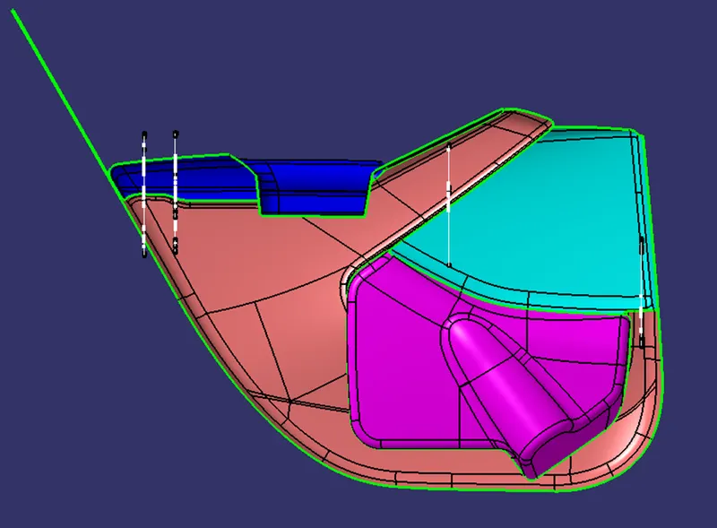
In the above fig., you can see that the surfaces along with the master section are given to me.
MASTER SECTION - Master section are the guides for a design that shapes the component after technical styling of class A surface. The Master section is parameterized model of the vehicle body that outlines the guidelines for the NPD team.
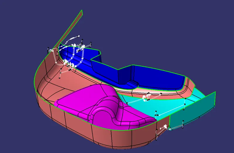
so here I have to create four parts that are mentioned below:
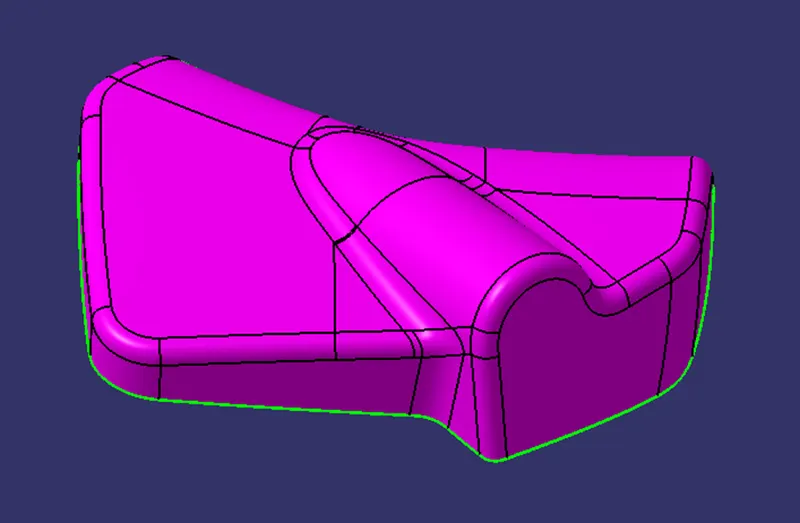
- Lower Substrate
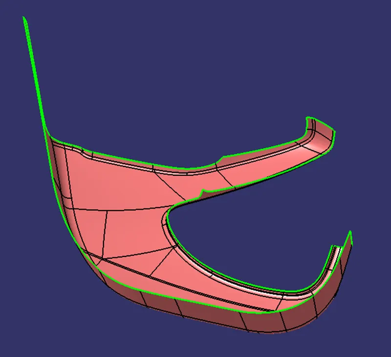
- Map Pocket
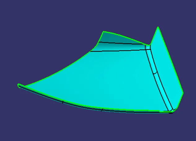
- Door Armrest
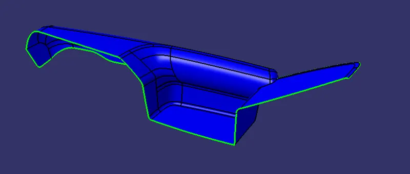
- Bottle Holder
Then I have to create the attachment features that are required for the assembly of the parts.
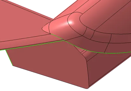
While checking the surfaces Door Arm Rest has an open boundary as below
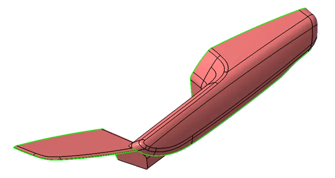
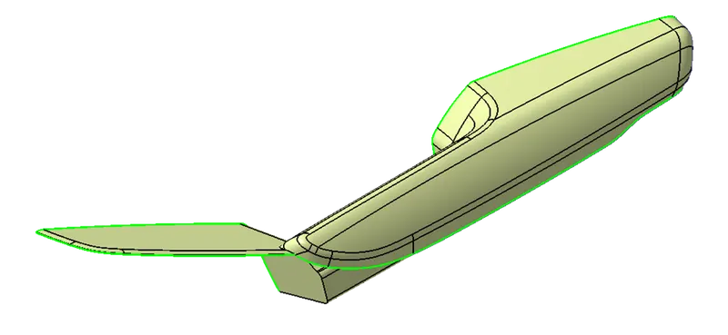
For creating closed boundary of this door arm rest, I have used join command with 0.05mm. Joined surface as shown below
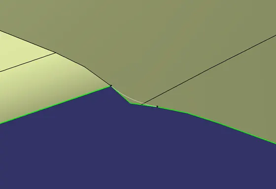
But the class A surface is not proper as shown below, so I split it with using a spline command for clear surface.
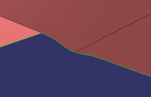
Improved class A surface
TOOLING AXIS - The tooling axis is defined as the direction in which the mold opens or core and cavity opens and closes. The selection of the correct tooling axis is important to ensure the component is taken out perfectly and also the cost of the component should be less.
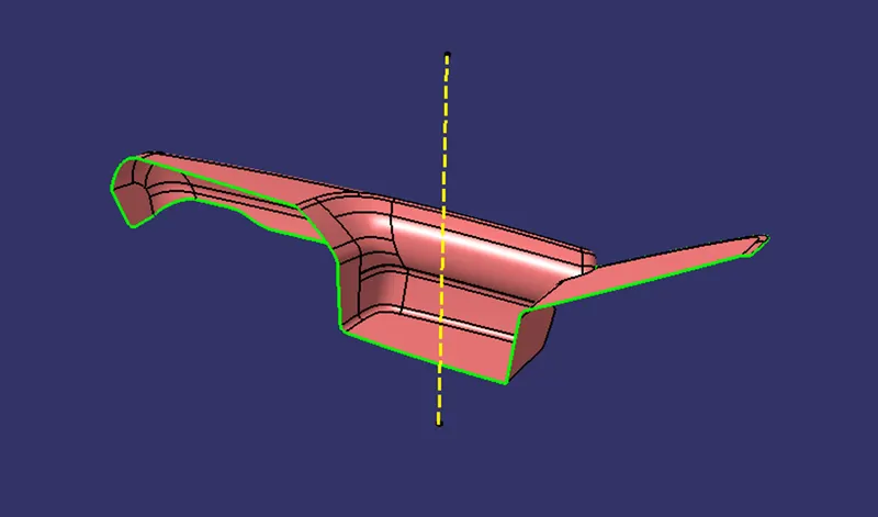
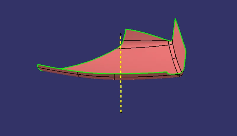
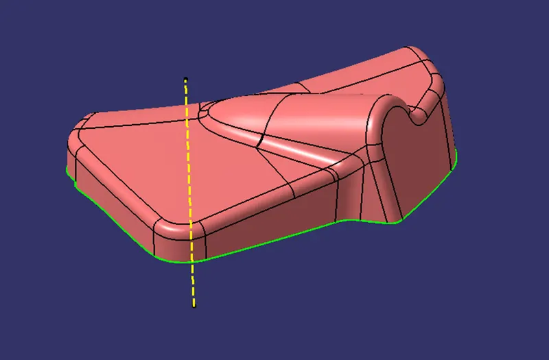
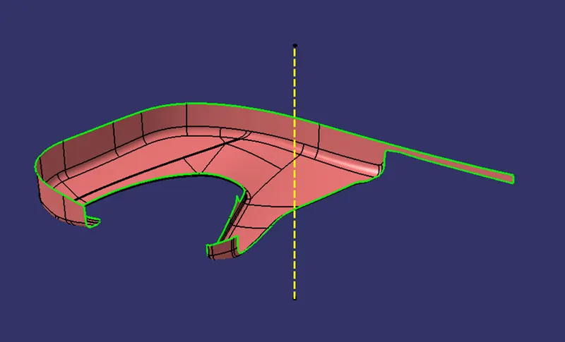
I will analyze the model and see from which direction I can see the whole model. so here the direction I have chosen for the tooling axis is along y-direction because along y-direction the whole model is visible properly. The tooling axis is shown below:
Door Arm Rest-
Map Pocket-
Bottle Holder-
Lower Substrate-
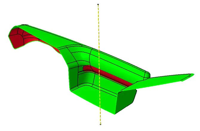
After creating the tooling axis I have done the draft analysis on the each part.
DRAFT ANALYSIS - Draft analysis is a technique to analyze whether the component created is manufacturable or not based on the draft conditions applied. So here I will provide the direction in which the component should be ejected to get the easy removal. My direction will be the tooling axis that I have created.
The minimum draft value for the Automotive plastic component is 3 degree
Door arm Rest-
Map Pocket-
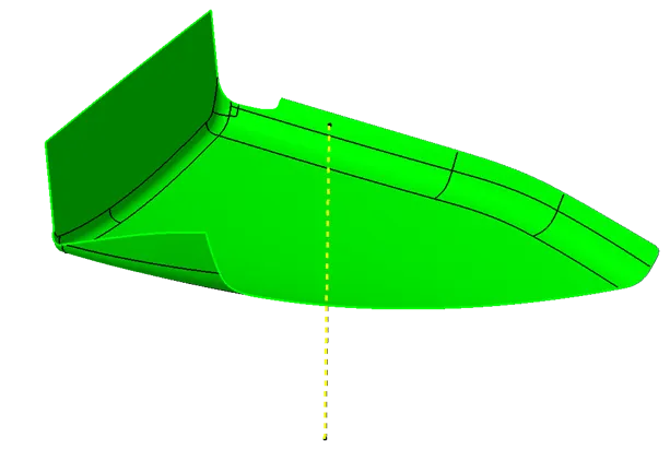
Bottle Holder-
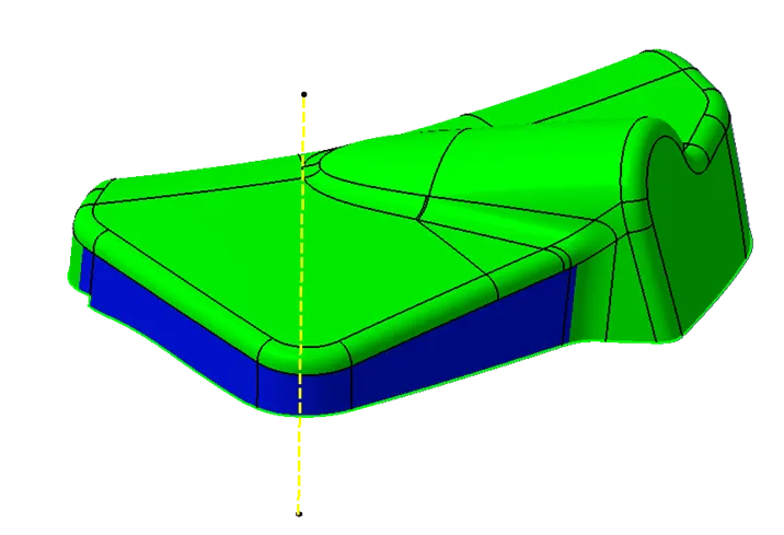
Lower Substrate-
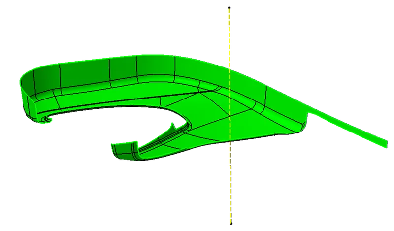
Draft Analysis Dialogue Box-
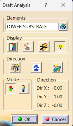
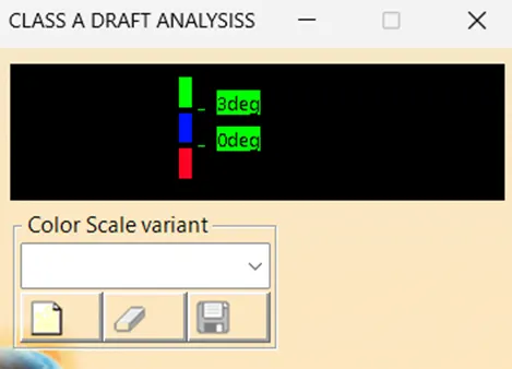
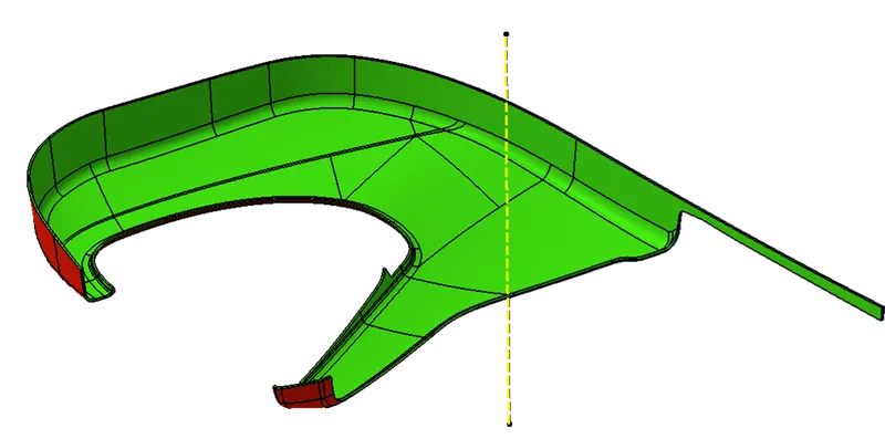
The color scale shown above denotes the following:
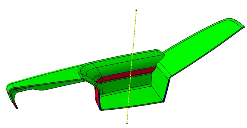
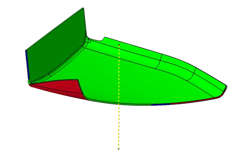
The Green color indicates that the draft provided is above 3 degrees.
The Blue color indicates that the draft provided is between o and 2.9 degrees.
The Red color indicates that the draft provided is negative.
CLASS B SURFACE - It is a surface that gives thickness from a class A surface. All the supporting features of the component will be formed on the B surface only. so we can say that Class B is an engineering surface and Class A is an aesthetic surface.
For creating the class B surface I have offset the Class A surface to 2.5 mm which is the thickness of the part according to the master section that is given as the input. After offsetting the class A surface to 2.5 mm I have extrapolated the class B surface up to the extent to which it can be trimmed later with the class C surface.
CLASS C SURFACE -
Class C surface is defined as the surface which connects the CLASS A and CLASS B SURFACE along the tooling direction. The tooling direction here will be my tooling axis.
For creating Class C I have extracted the boundaries of the class A surface and swept the extract along the draft direction. giving a 3 degrees draft.
In some of the portion I have used the reference surface option in sweeping for the portion that does not require a sweep with draft direction.
Then I have joined the sweeps that I created and if some sweep is extending I have trimmed it according to my requirement to get the class C surface. After creating the class C surface I have joined it with the class A surface.
Then after creating I have made sure that I have a close surface. so for validating that I have to use the boundary option and clicked on the surface I got an error which proves that I have a closed surface.
DRAFT ANALYSIS OF CLOSED BODY -
1. Door Arm Rest-
2. Map Pocket
3.Bottle Holder
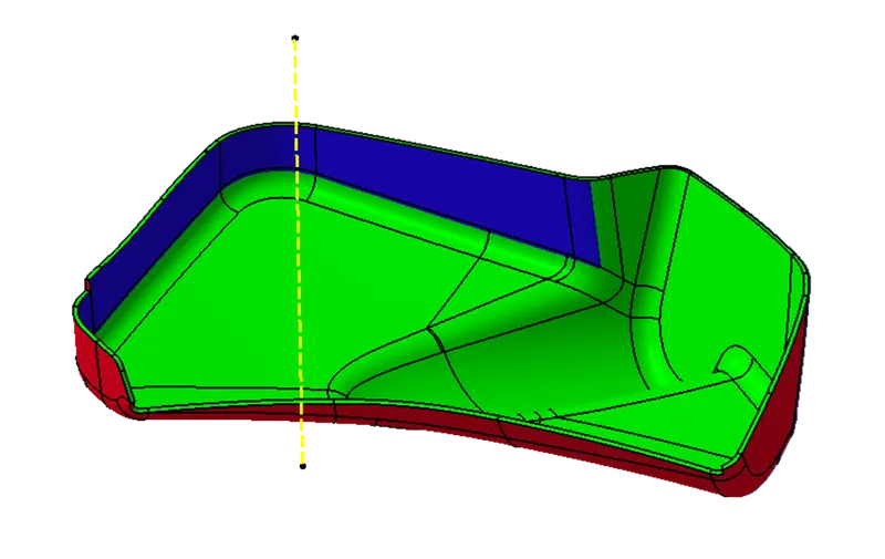
4.Lower Substrate
B SIDE FEATURES -
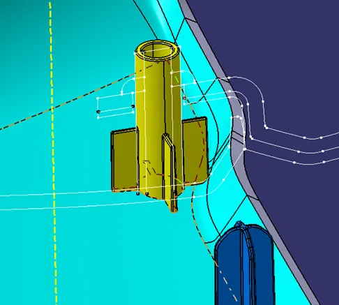
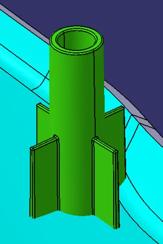
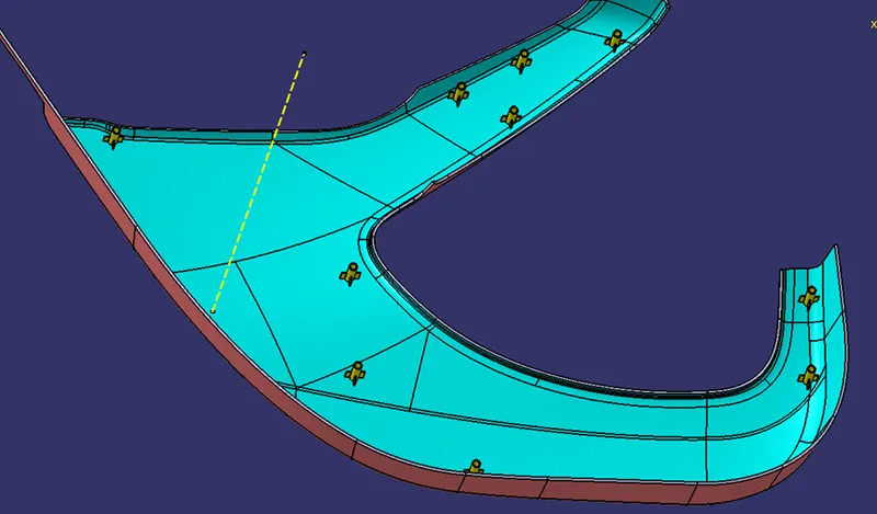
HEAT STAKE & RIB CREATION -
Heat staking also known as thermoplastic staking is the process of joining two dissimilar materials together. In heat staking, we use local heating and cooling to raise the temperature of plastic components and allow plastic reforming to be carried out. This reforming can be used in a wide variety of applications.
Applications range from staking plastic bosses for assembly of car door panels to joining PCBs to plastic housings. Benefits of this technique include; no vibration damage, no particulates, the ability to stake metalized coated applications, and the capability to stake in difficult to access or restricted areas.
The progressive melting of plastic under continuous pressure forms the head. When staking the right combination of heat and pressure for the application is critical.
The advantages of Heat staking are as follows:
1) simplification of the machinery
2) Reduced cost of machinery
3)Multiple fastening points
4) Allows higher density of welds compared to hot air cold form or ultrasonic welding.
1.We will take a reference from master section for sketching a heat stake, and isolate them.
2.That sketch will use for pad till master section height, after that will provide a 0.5 degree draft both inside and outside wall.
3.After that will create a rib sketch and pad it with thick and neutral fiber to 1mm, and this rib will be trimmed with heat stake
4.0.25mm fillet will be provide on overall heat stake and rib.
5.By using parallel curve we provide points repetition command with 60mm distance.
6.After that we simply translate the whole body of heat stake and rib from point to point method.
LOCATOR CREATION -
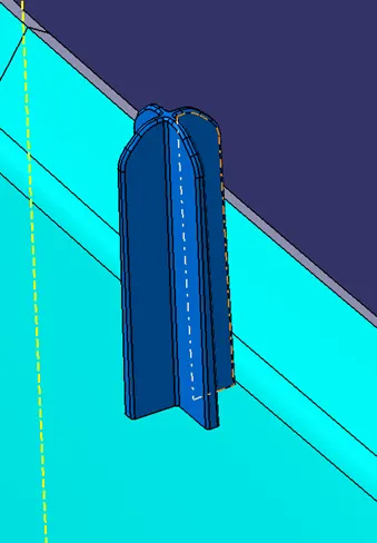
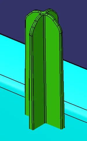
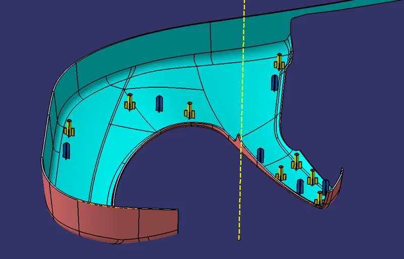
1.Locater we provide for correct position on the injection machine, to ensure proper alignment between molds
2.Locator can easily drawn by sketch and pad it, and provide a 0.5 degree draft also.
3.After that we provide a chamfer of 2.5mm and also fillet that faces, finally we provide overall fillet of 0.25mm
4.By simply adding a point on class B surface we will translate a locator.
5.Generally two locater will be enough for provide an proper alignment
DOG HOUSE CREATION -
Dog house is an engineering feature used in the plastic trim design. Doghouses are used as supporting features. Sometimes other engineering features like snaps; locators, etc. are mounded on them to increase their strength.
Dog houses are subjected to draft analysis to prevent breakage of the component during ejection from the mold cavity. Dog house and other engineering components are built on B-surface.
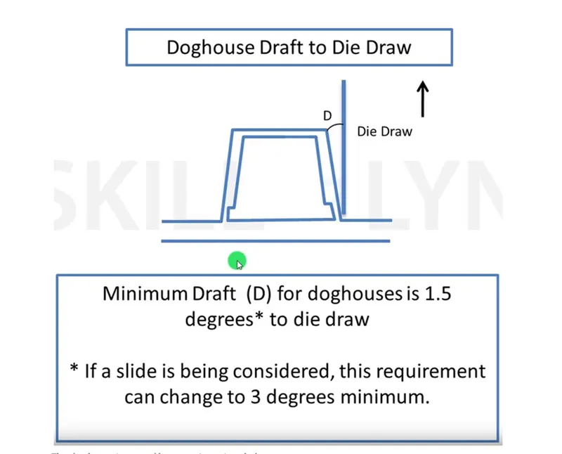
1.Dog houses are used as supporting feature. Dog house are created to avoid sink marks on class A surface
2.On front side of dog house at least 60-80mm surface need to be free, there is no other plastic feature created, because of lifter movement.
3.We will take a reference of dog house creation from below drawing.
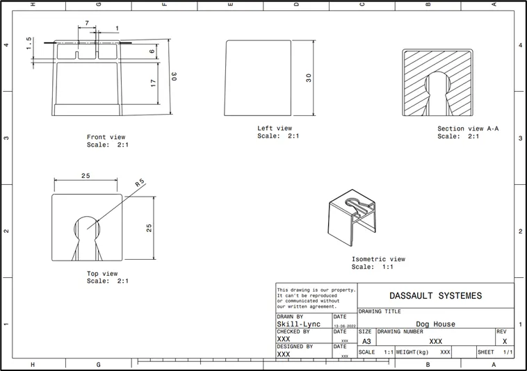
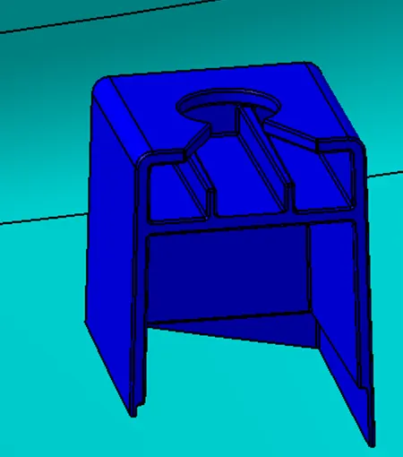
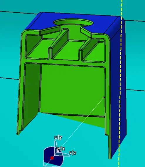
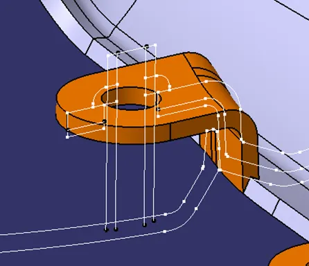
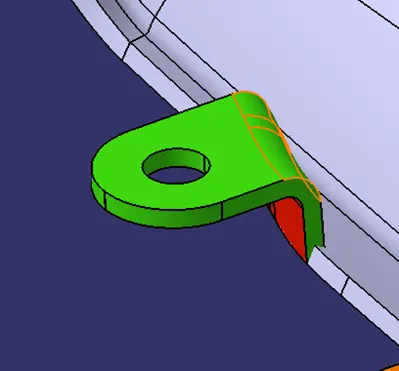
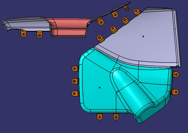
FLANGES CREATION-
1.Flanges are created for part fixation, it will be mount on heat stake and above portion of heat stake will melted, that will be stuck on flange and part gets fixed.
2.We will take a reference from master section for sketching a Flange, and taken reference from master section will be isolated.
3.We will use a class C surface for reference, and create a sweep along with it, after that will be trimmed with surface.
4.For an inner hole will draw a sketch and extrude it simply split it in part workbench
5.We provide a 0.5 degree draft on outer edges and inner hole and provide fillets.
PUSH-PIN FITMENT -
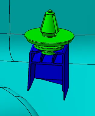
Push pins are used for joining one component to another. These are basically attached to the dog house.
Before adding to dog house i have created axis along with Y-direction and created a center axis on push-pin
After thay by using coincident constrain i have assembled the push pin in dog house.
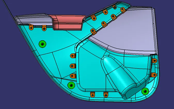
Now the part creation and the attachment feature creation are done.
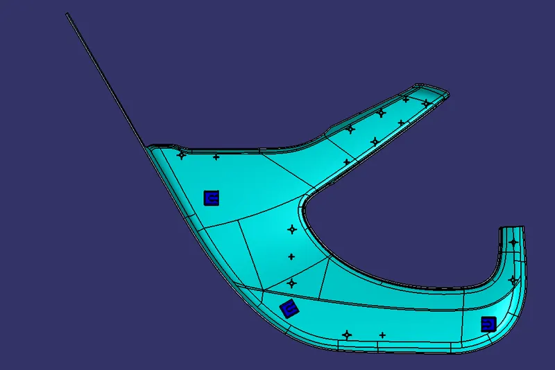
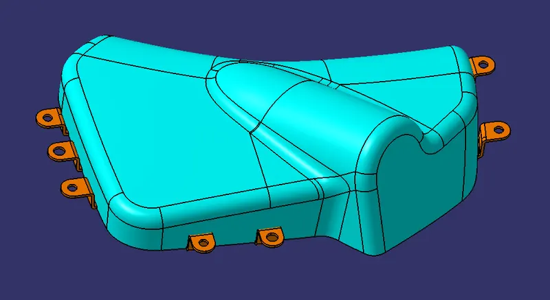
RESULT - The draft analysis of individual part is shown below:
1) Lower substrate
2) Bottle Holder
3) Map pocket
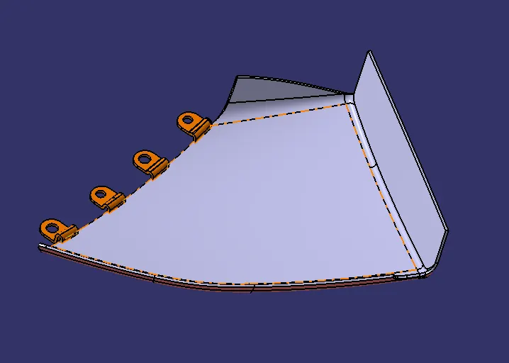
4) Door Armrest
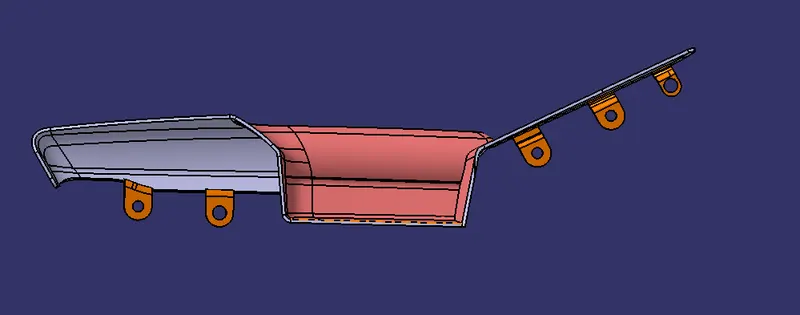
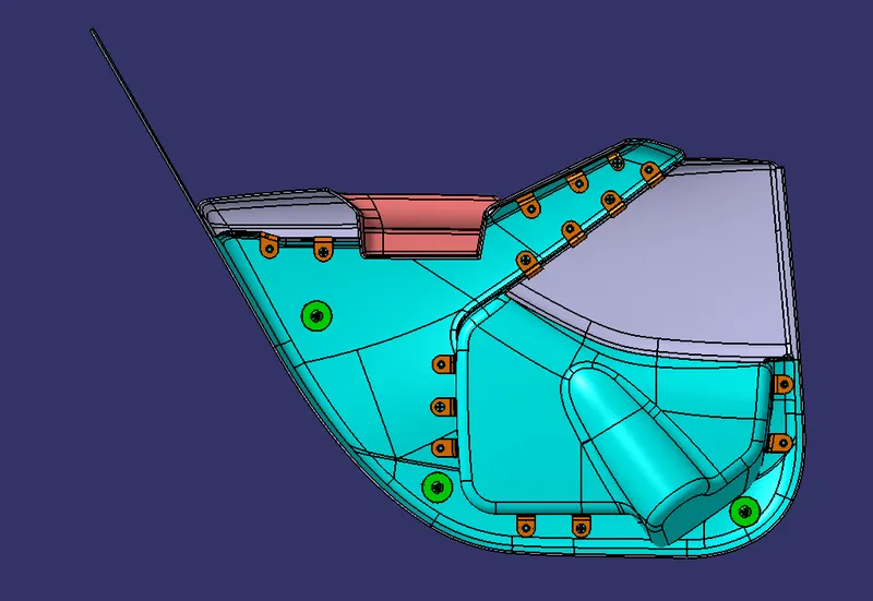
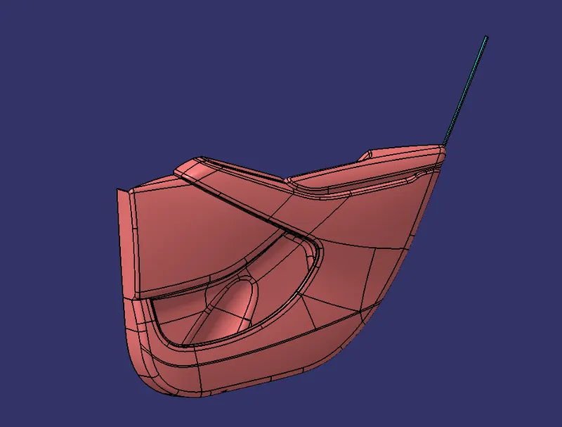
The final CAD model of the Door Trim panel is shown below:
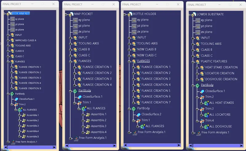
The tree structure of the CAD model is shown below:
CONCLUSION - This concludes the creation of the Door Trim Panel along with engineering features using the master section given as the input.