CATIA-Week 8.2- Switch Bezel Design
AIM:
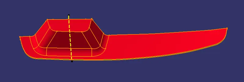
Create the Switch Bezel Plastic component using given class-A surface, create a tooling direction and perform draft analysis on the model.
OBJECTIVE :
- To ensure that the model fulfils the draft angle criteria.
- To make a tooling axis, use the bisecting approach.
- Draft analysis must be performed on the provided Class A surface.
- To create the necessary Class B and Class C surfaces.
- Using the Close Surface feature, create a solid body from a surface.
CLASS A SURFACE :
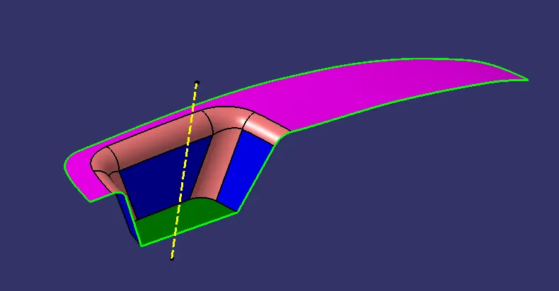
- Class A surfaces are those surfaces which are curvature continuous while providing the simplest mathematical representation needed for the desired shape and does not have any undesirable waviness.
- The Class A surface is the used to begin the design of a product.
- All the further intricacies of the component are created based on the Class A surface.
CLASS B SURFACE :
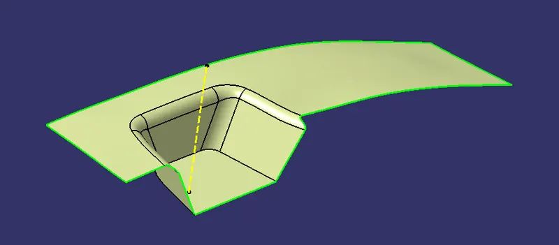
- The Class B surface is created from the Class A surface , keeping the thickness of the component in check.
- The Class B surface resembles an offsetted surface from the Class A.
CLASS C SURFACE :
- The Class C surface is used to bind the Class A and Class B surface together inorder to form a closed surface.
PROCEDURE :
Creating Tooling Axis
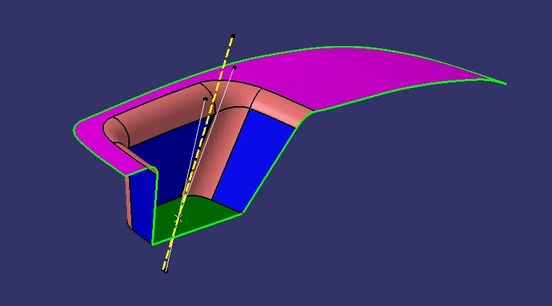
- Initially the given Class-A surface was imported and checked for any discrepencies in the boundary.
- The base surface of the component was extracted.
- Two sketches were created based on the adjacent sides of the Class A surface.
- Finally a Tooling axis was created from these two reference lines using Bisecting option.
Creating Class B Surface
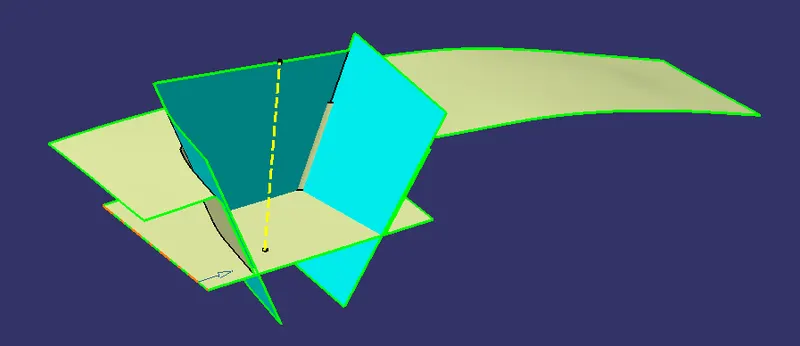
- The B surface was created from three seperate sets of surfaces which was finally trimmed together to form a single surface.
- The required surfaces were obtained from the Class A surface using Extract command.
- These surfaces were further expanded using Untrim and Extrapolate commands.
- The protuding surfaces were trimmed using the Trim command and a proper continuous surface was obtained.
- These surfaces were offsetted according to the required thickness of the component.
- The required fillets were provided to complete the Class B surface.
Creating Class C Surface
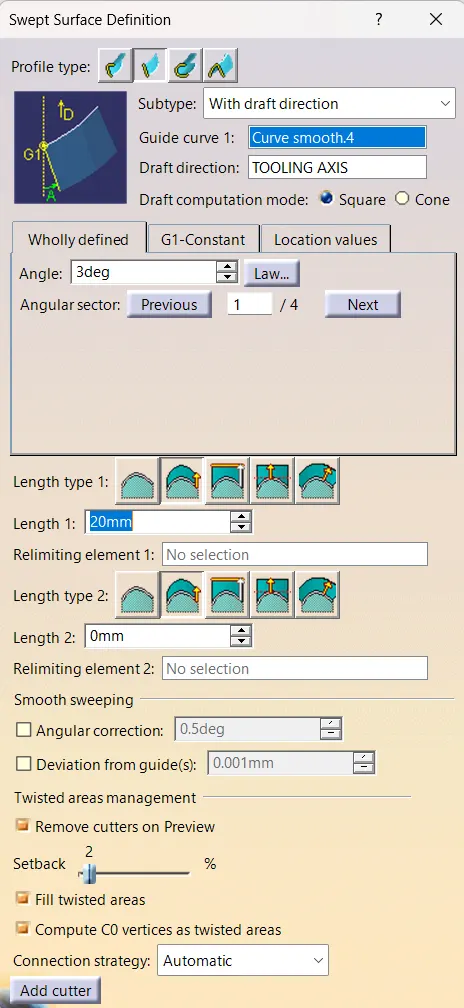
- The Class C surface connects the Class A and Class B surface.
- Initially the outline of the Class A surface was obtained using the Boundary command.
- The Curve smooth feature were used to enhance the the obtained surfaces.
- The the Sweep command was used along With draft direction, with a draft angle of 3 degree.
- The Curve smooth feature were used to enhance the the obtained surfaces.
- The required portions were Extrapolated and Trimmed.
Creating Solid Body
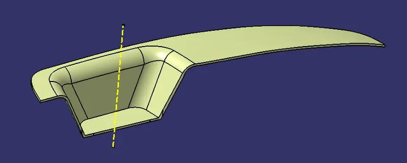
- Finally the Class A, B and C surfaces were trimmed together to form a closed surface.
- Using the surface created the solid component was obtained using the Close surface feature present in the part workbench.
- The Tooling axis, Class A, B and C surfaces were published.
Draft Analysis
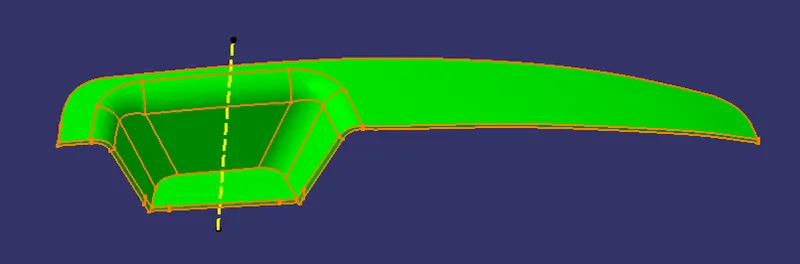
- The Drafting analysis was performed using the Feature Draft Analysis command.
- Using this command the compass was set on the main tooling axis and the Draft angle was changed to 2.9 degree.
MODEL RESULTS :
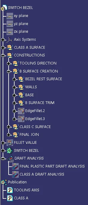
Feature Tree
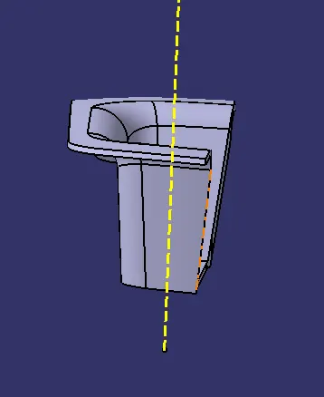
Front view
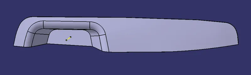
Top view
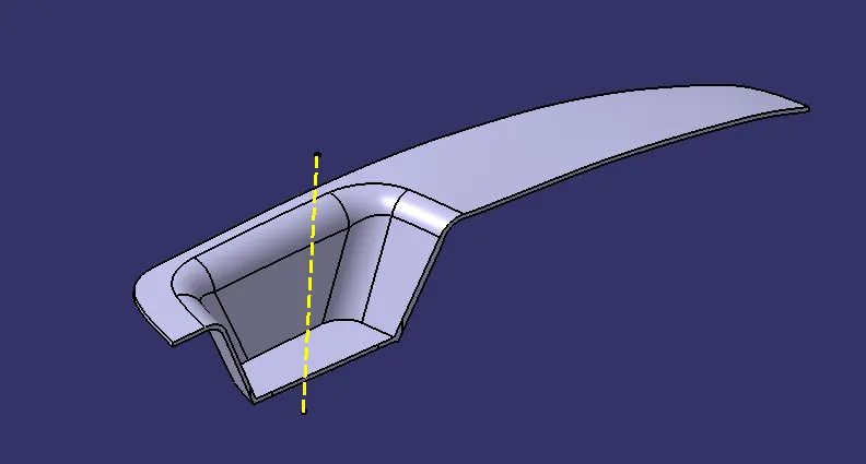
Side view
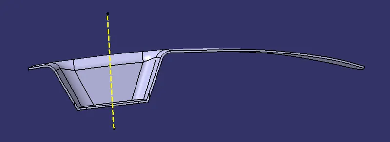
Isometric view
CONCLUSION :
- The creation of Tooling axis and Draft analysis were performed.
- The solid component was created from the surface geometry.
- The necessary screenshots and files were attached.