Week 11 - Final project
OBJECTIVE :
The Objective of the project is to development of vehicle interior door trim panel by using CATIA V5 With given class-A surface along with the master seection. Also Create the side attachment feature as per design rules.
INTRODUCTION :
The door panel is the interface between the interior of the car and inner working of the door. Generally, the door panel is divided into parts for easy designing like arm rest, map pocket, Lower substrate. These require one of the toughest requirements amoung the interior parts of the car. This should be designed to with stand the load while being less than 2mm thickness and also to protect the occupants during collisions.
Class-A Surfaces :-
In automotive design a Class-A surface in any of a set of from surface of high efficiency and quality. Although strictly its nothing more than saying have curvature alignement to ideal aesthetical reflection quality, many people interpret class-A surface to have G2 or even G3 curvature continuity to one another. Class-A surface is creating by using computer Aided digital applications. Class-A surface modellers are also called digital sculptors in the industry.
Class-B Surface :-
Class B surface are Engineering Surfaces which are invisible to the eyes or often on the back side of the Class A surface. It is mainly the thickness of the component or Class A. These surfaces need to be designed as per the Class A surface i.e., the continuity, thickness of the component, functionality etc should be maintained. These surfaces include the main engineering features such as Screw bosses, Ribs, Snaps, Stiffeners and fixations. B surfaces also do not contain any aesthetic styling content and textures since it is not visible to eyes.
Class- C Surface :-
Class C surfaces are connectors between Class A and Class B surfaces. This surface connects both A and B surfaces along the tooling Axis. It contains the draft as per the design. It is basically the thickened surface between both A and B surface.
Tooling Axis:
Tooling Axis is the direction in which the Mold opens and closes. Part Drafts are generally given along this axis.
3) DESIGN METHODOLOGY OF DOOR TRIM PANEL :
TOOLING AXIS CREATION
CLASS B CREATION
CLASS C CREATION
CLOSED BODY CREATION
DRAFT ANALYSIS
4) PROCEDURE OF DOOR TRIM PANEL :
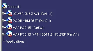
The door panel is divided into four parts for easly to design. There are,
- Lower substrate
- Door Arm Rest
- Map Pocket.
- Map Pocket With Bottle Holder.
A) Door Arm Rest :-
Step 1: Design Check (Pre Check) on received Class A :-
- After receiving the Class-A for the connectivity of the surfaces on it.
- Use boundary operation and disassemble.
- Check for discontinuous Surface.
- The check is over if any discontinuities do not arise.
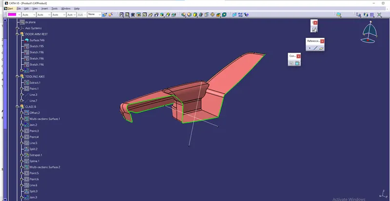
Step 2: Determine the tooling Axis :-
- Identify faces which can potentially create problems while manufacturing.
- Surfaces at angles along a desired Tooling Axis.
- Extract a plain surface and create a point on its center for Axis system creation.
Step 3: Draft Analysis on Class-A and Possible Creation of Side Tooling Axis :-
- Change View Mode Customization to Material mode.
- Go to INSERT--->ANALYSIS--->FEATURE DRAFT ANALYSIS and move the compass to the moving Axis.
- Change the range to 3°. Apply the settings as shown in below image.
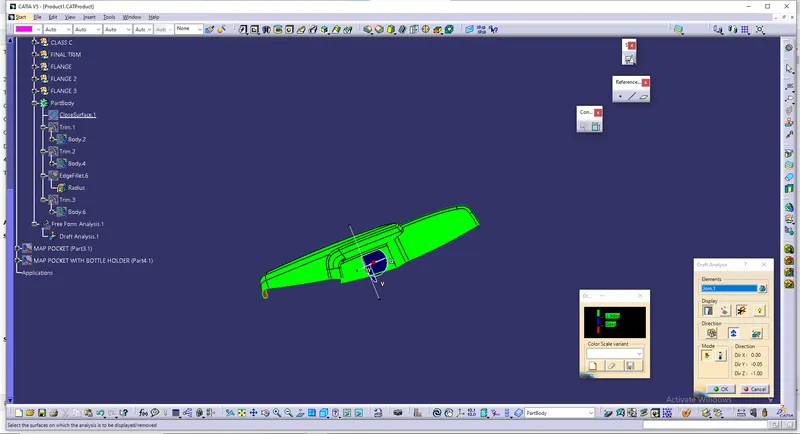
- The input Class A also has walls having negative angle to the tooling axis.
- This can be an issue while manufacturing the component as it would be very difficult to draw from the molds.
- So, this design needs to consider Various Side Tooling Options.
- Here also we can see that some faces are not clearing draft analysis and it is due to the improper class A surface and we have to imform our styling team to modify the class A surface.
Step 4: Class-B Surface Creation :-
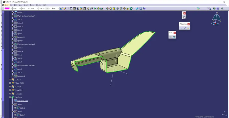
This can be done by offseting the class-A surface and by reparing the patches that are forrmed while offsetting the class-A surface.
- First offset the class-A surface
- We can observe it has created patches at two stages.
- So we have to repair them by using multi section surface command.
- Name the developed repaired surface ass Class-B Surface and make it publish.
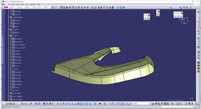
Step 5: Class-C Surface Creation :-
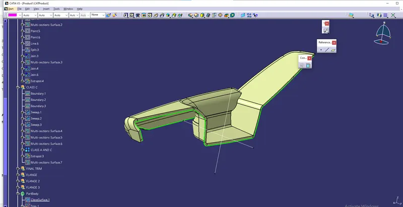
- Extract Class A boundary and convert to Smooth Curve.
- Sweep the curve to the Class A.
- Sweep value should be greater than the Thickness required for part.
- The obtained sweep is shown in Figure.
- Join the Class A Surface with the Class C surface to create a single surface entity.
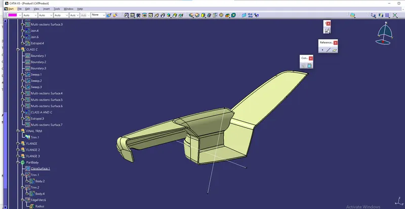
Step 6: Enclosed Surface Creation :-
- Trim the obtained surface with Class B surface.
- Make Slight Adjustments by extrapolating small values and trimming to obtain a final Enclosed Surface.
- The final Enclosed Surface Obtained is shown in Figure.
Closed Surface :-
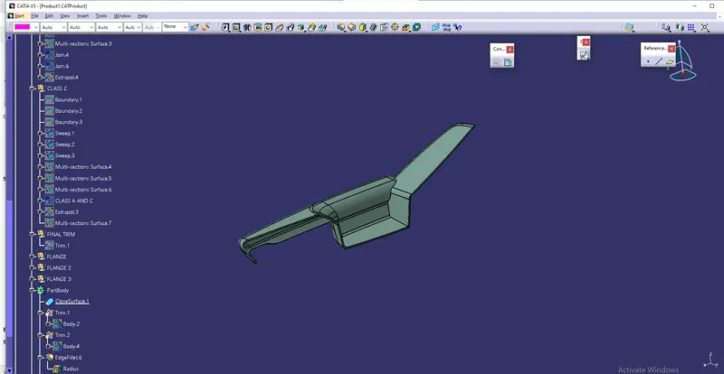
Make the final trim to solid part using close surface.
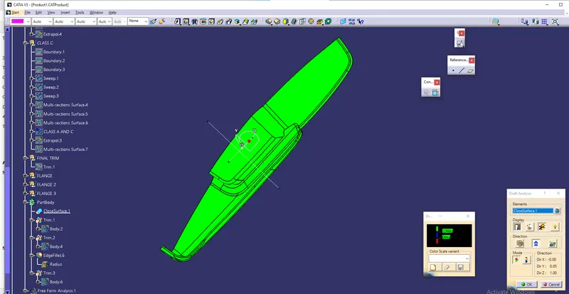
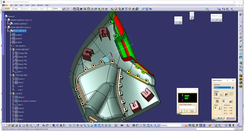
Step 7: Perform Draft Analysis on Final Enclosed Surface:
- Change View Mode Customization to Material mode.
- Go to INSERT---> ANALYSIS---> FEATURE DRAFT ANALYSIS and move the compass to the Main Tooling Axis.
- Change the range to 3°. Apply the settings as shown if Figure.
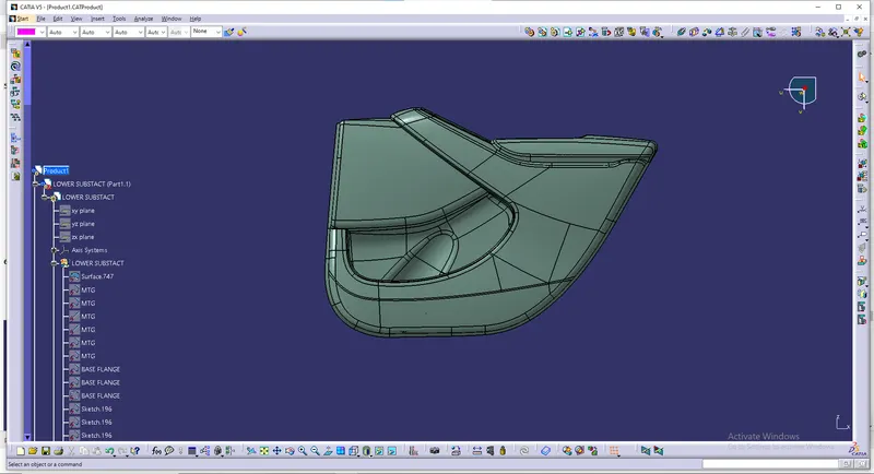
B) Lower Substrate :-
Step 1: Design Check (Pre Check) on received Class A :-
- After receiving the Class-A for the connectivity of the surfaces on it.
- Use boundary operation and disassemble.
- Check for discontinuous Surface.
- The check is over if any discontinuities do not arise.
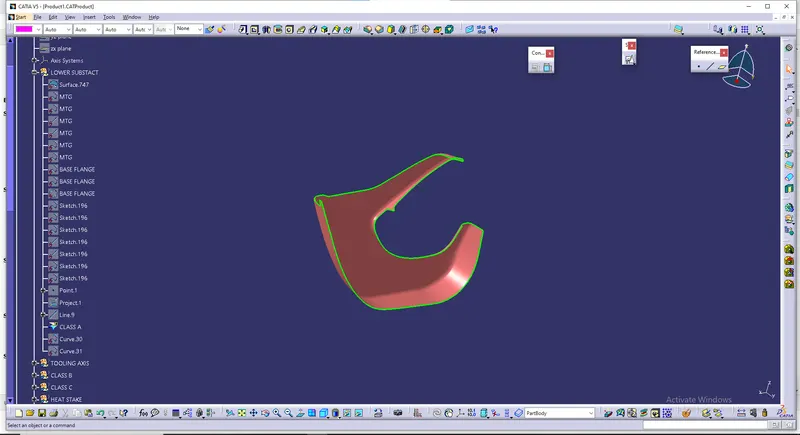
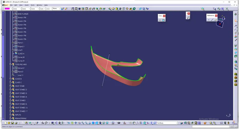
Step 2: Determine the tooling Axis :-
- Identify faces which can potentially create problems while manufacturing.
- Surfaces at angles along a desired Tooling Axis.
- Extract a plain surface and create a point on its center.
- Create the intersection by using the plane.
- Create the bisecting line for tooling axis by taking dummy tooling axis.
Step 3: Draft Analysis on Class-A :-
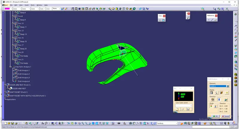
- Change View Mode Customization to Material mode.
- Go to INSERT--->ANALYSIS--->FEATURE DRAFT ANALYSIS and move the compass to the moving Axis.
- Change the range to 3°. Apply the settings as shown in below image.
Step 4: Class-B Surface Creation :-
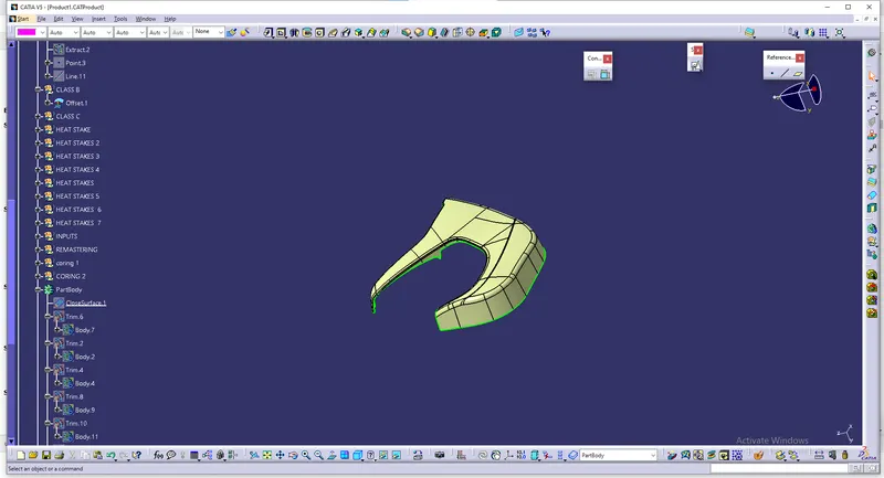
- The creation of class-B surface can be done by smiply offsetting the class-A surface to the required distance and required direction.
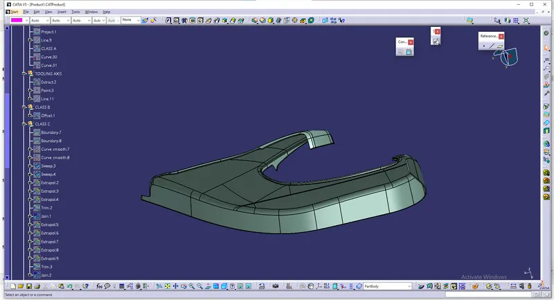
Step 5: Class-C Surface Creation :-
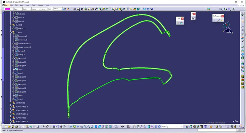
- Extract Class A boundary and convert to Smooth Curve.
- Sweep the curve to the Class A.
- Sweep value should be greater than the Thickness required for part.
- The obtained sweep is shown in Figure.
- Join the Class A Surface with the Class C surface to create a single surface entity.
Step 6: Enclosed Surface Creation :-
- Trim the obtained surface with Class B surface.
- Make Slight Adjustments by extrapolating small values and trimming to obtain a final Enclosed Surface.
- The final Enclosed Surface Obtained is shown in Figure.
Closed Surface :-
Make the final trim to solid part using close surface.
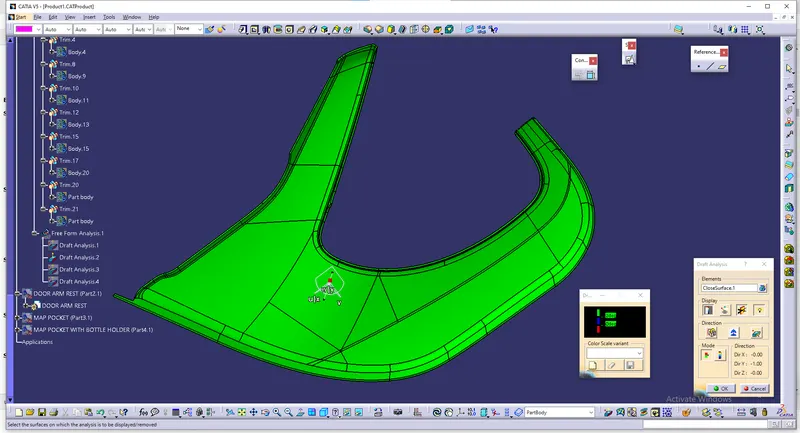
Step 7: Perform Draft Analysis on Final Enclosed Surface:
- Change View Mode Customization to Material mode.
- Go to INSERT---> ANALYSIS---> FEATURE DRAFT ANALYSIS and move the compass to the Main Tooling Axis.
- Change the range to 3°. Apply the settings as shown if Figure.
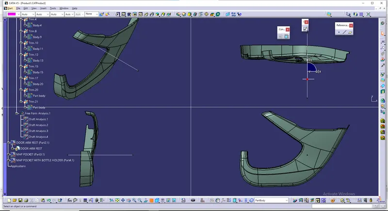
Views of Lower Substrate :
C) Outer Map Pocket :-
Step 1: Design Check (Pre Check) on received Class A :-
- After receiving the Class-A for the connectivity of the surfaces on it.
- Use boundary operation and disassemble.
- Check for discontinuous Surface.
- The check is over if any discontinuities do not arise.
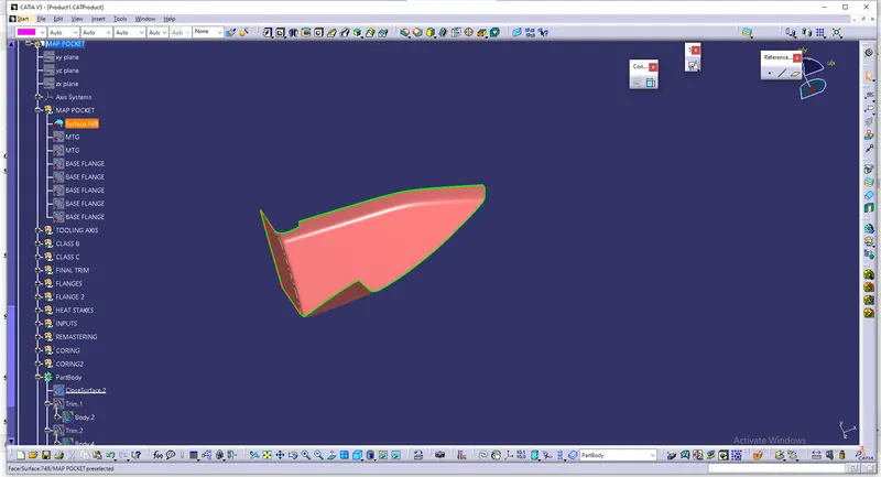
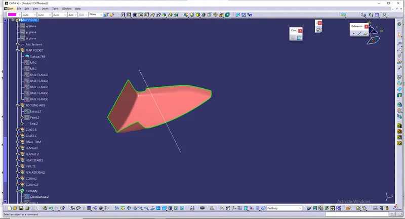
Step 2: Determine the tooling Axis :-
- Identify faces which can potentially create problems while manufacturing.
- Surfaces at angles along a desired Tooling Axis.
- Extract a plain surface and create a point on its center for Axis system creation.
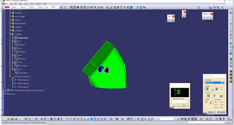
Step 3: Draft Analysis on Class-A :-
- Change View Mode Customization to Material mode.
- Go to INSERT--->ANALYSIS--->FEATURE DRAFT ANALYSIS and move the compass to the moving Axis.
- Change the range to 3°. Apply the settings as shown in below image.
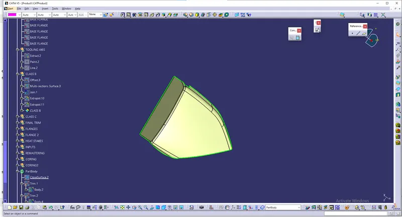
Step 4: Class-B Surface Creation :-
- The creation of class-B surface can be done by smiply offsetting the class-A surface to the required distance and required direction.
Step 5: Class-C Surface Creation :-
- Extract Class A boundary and convert to Smooth Curve.
- Sweep the curve to the Class A.
- Sweep value should be greater than the Thickness required for part.
- The obtained sweep is shown in Figure.
- Join the Class A Surface with the Class C surface to create a single surface entity.
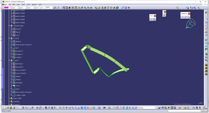
Step 6: Enclosed Surface Creation :-
- Trim the obtained surface with Class B surface.
- Make Slight Adjustments by extrapolating small values and trimming to obtain a final Enclosed Surface.
- The final Enclosed Surface Obtained is shown in Figure.
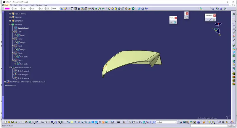
Closed Surface :-
Make the final trim to solid part using close surface.
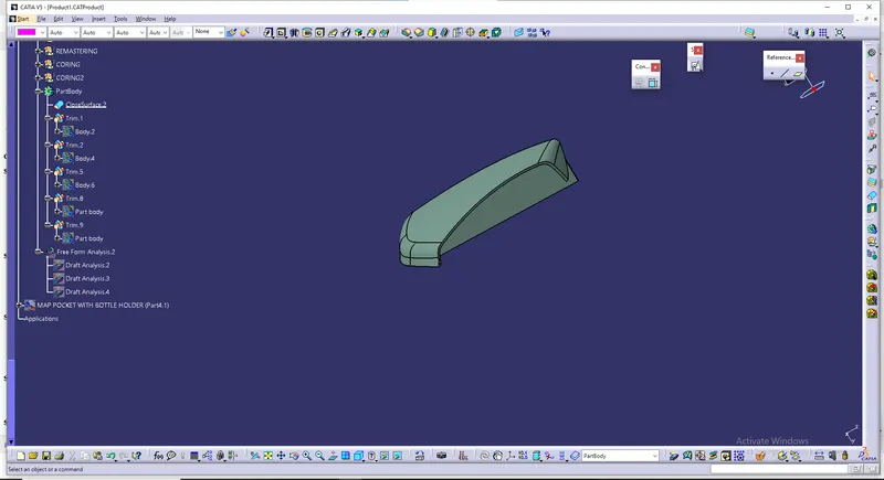
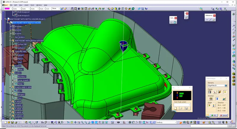
Step 7: Perform Draft Analysis on Final Enclosed Surface:
- Change View Mode Customization to Material mode.
- Go to INSERT---> ANALYSIS---> FEATURE DRAFT ANALYSIS and move the compass to the Main Tooling Axis.
- Change the range to 3°. Apply the settings as shown if Figure.
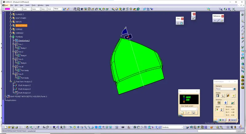
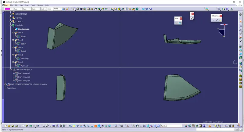
Views of Outer Map Pocket :
D) Inner Map Panel :
Step 1: Design Check (Pre Check) on received Class A :-
- After receiving the Class-A for the connectivity of the surfaces on it.
- Use boundary operation and disassemble.
- Check for discontinuous Surface.
- The check is over if any discontinuities do not arise.
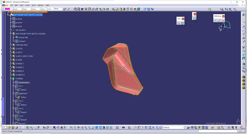
Step 2: Determine the tooling Axis :-
- Identify faces which can potentially create problems while manufacturing.
- Surfaces at angles along a desired Tooling Axis.
- Extract a plain surface and create a point on its center.
- Create the intersection by using the plane.
- Create the bisecting line for tooling axis by taking dummy tooling axis.
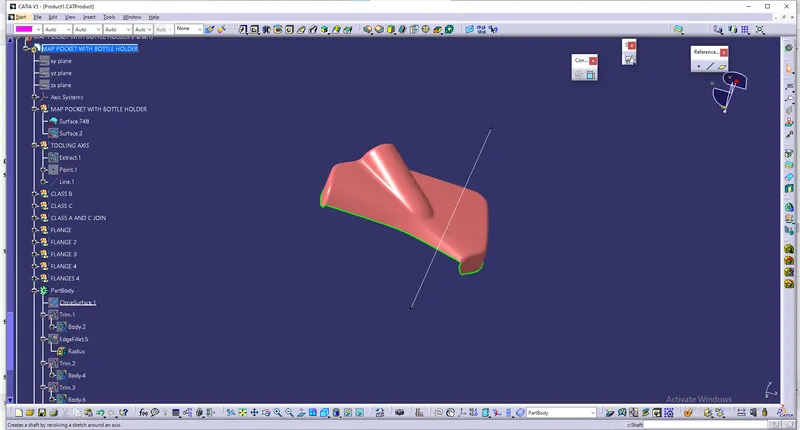
Step 3: Draft Analysis on Class-A :-
- Change View Mode Customization to Material mode.
- Go to INSERT--->ANALYSIS--->FEATURE DRAFT ANALYSIS and move the compass to the moving Axis.
- Change the range to 3°. Apply the settings as shown in below image.
Step 4: Class-B Surface Creation :-
- The creation of class-B surface can be done by smiply offsetting the class-A surface to the required distance and required direction.
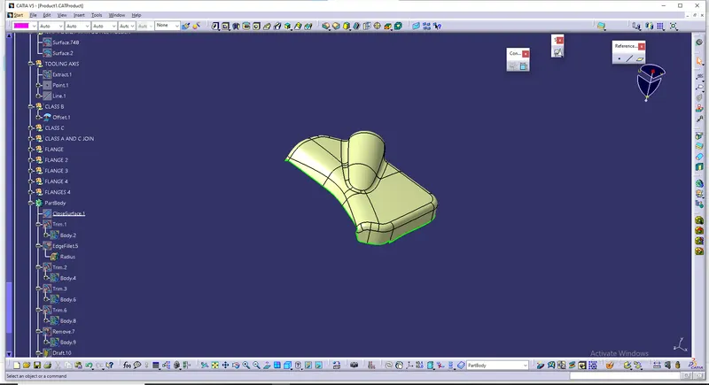
Step 5: Class-C Surface Creation :-
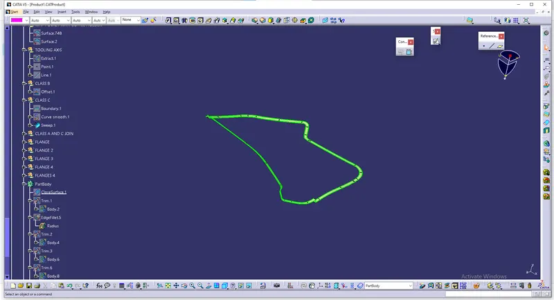
- Extract Class A boundary and convert to Smooth Curve.
- Sweep the curve to the Class A.
- Sweep value should be greater than the Thickness required for part.
- The obtained sweep is shown in Figure.
- Join the Class A Surface with the Class C surface to create a single surface entity.
Step 6: Enclosed Surface Creation :-
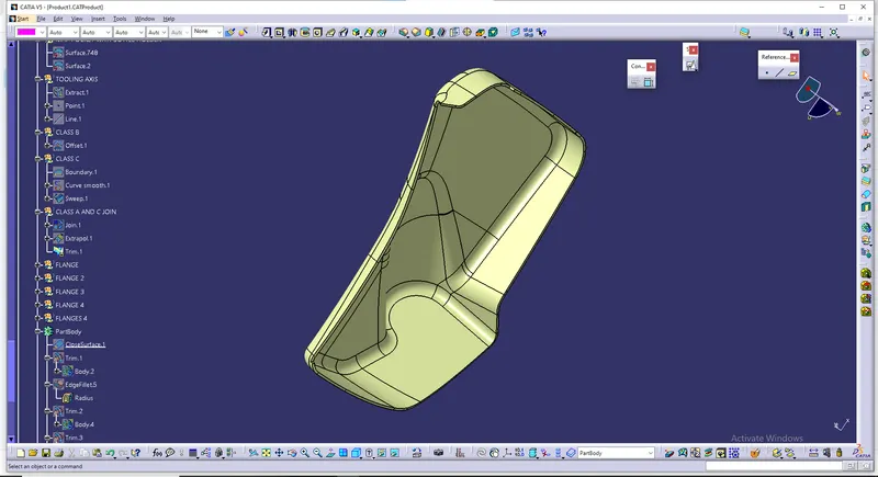
- Trim the obtained surface with Class B surface.
- Make Slight Adjustments by extrapolating small values and trimming to obtain a final Enclosed Surface.
- The final Enclosed Surface Obtained is shown in Figure.
Closed Surface :-
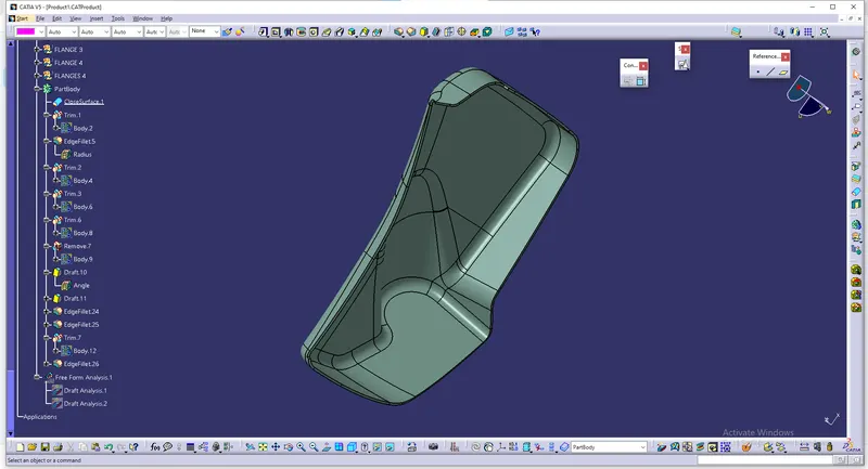
Make the final trim to solid part using close surface.
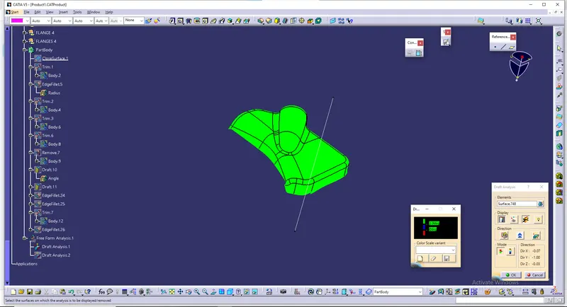
Step 7: Perform Draft Analysis on Final Enclosed Surface:
- Change View Mode Customization to Material mode.
- Go to INSERT---> ANALYSIS---> FEATURE DRAFT ANALYSIS and move the compass to the Main Tooling Axis.
- Change the range to 3°. Apply the settings as shown if Figure.
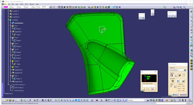
Views of Inner Map Pocket :
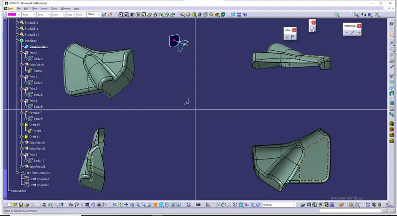
5) VIEWS OF DOOR TRIM PANEL ASSEMBLY :
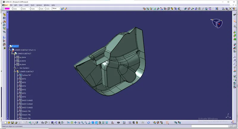
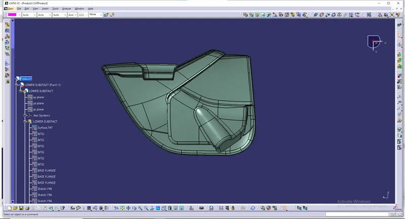
6) DESIGN OF B-SIDE FEATURES :
FLANGES - Flanges are the elements that are needed to join different components together. So here I have to make flanges on the door armrest and the map pocket. Following the master section, given as the input basically the measurements and location of the flange. I have created the flanges. First I have created the flange on the outer map pocket. For creating the flanges I have taken extraction of the curve and made a point on that curve then created one plane on that point followed by creating a sketch on that plane taking the point created as the origin.
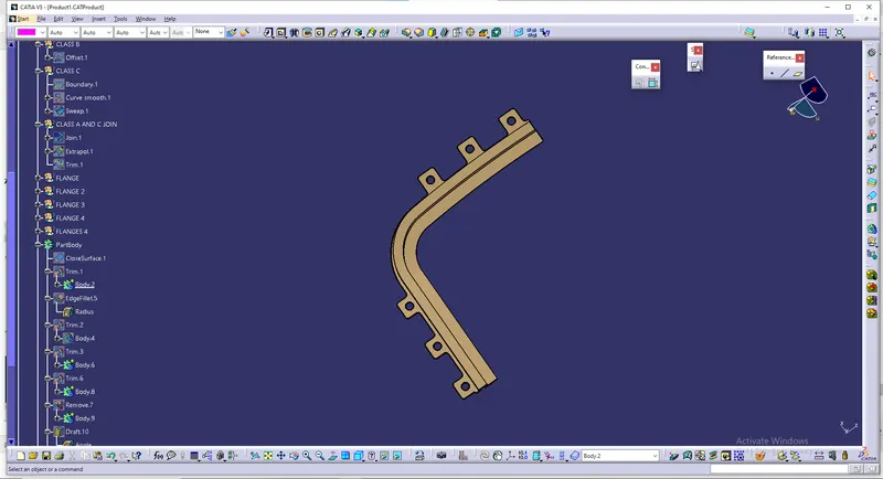
Then I have provided the draft and fillets to the flange. The fillets value can be taken from the master section master if given or u can provide a minimum fillet of 1 mm. coming to the draft value here for the outer map pocket I have provided 3 degrees and but if the flange size is less than u can provide a minimum draft of 0.5 degrees. After providing the draft and fillets the flange looks like this:
Then I have copied the flange body and paste it on the main part body using the as result with a link option in paste special.
After pasting I have translated the flange using the point-to-point translation feature keeping in mind the spacing rule that is the gap between two flanges should be 60 - 100 mm. Then after the translation, I have used the union trim boolean operation to make one single body.
The same thing I did for the other parts also that is extracted the curves in which the flange is required then I made a point and plane then sketched on it to create flanges later provided drafts and fillets.
The flanges of the inner map pocket are shown below for this part I have given 0.5 degrees draft to the flanges.The flanges of the Door Armrest are shown below for this part also the draft is 0.5 degrees:After creating the flanges I have created the dog house.
Heat staking - Heat staking also known as thermoplastic staking is the process of joining two dissimilar materials together. In heat staking, we use local heating and cooling to raise the temperature of plastic components and allow plastic reforming to be carried out. This reforming can be used in a wide variety of applications.
Applications range from staking plastic bosses for assembly of car door panels to joining PCBs to plastic housings. Benefits of this technique include; no vibration damage, no particulates, the ability to stake metalized coated applications, and the capability to stake in difficult to access or restricted areas.
The progressive melting of plastic under continuous pressure forms the head. When staking the right combination of heat and pressure for the application is critical.
The advantages of Heat staking are as follows:
1) simplification of the machinery
2) Reduced cost of machinery
3)Multiple fastening points
4) Allows higher density of welds compared to hot air cold form or ultrasonic welding.
Before creating the heat stakes I have created the holes on all the flanges that I created earlier. For the hole, I have created one point on the upper face of the flange and created a sketch on it.
Then I have extruded the sketch and split it from the outer map pocket to get the hole.
Then for creating the heat stakes I have offset the extrude created to 0.5 mm because the heat stake should maintain a distance of 0.5 mm from the hole. The offset is shown below:
Then I have thickened the offset surface to get the solid body. The thickness value was 2mm and provide a draft of 0.5 mm.
here one thing we need to check the distance of the upper face of the heat stake from the flange surface it should be close to 7mm according to the master section given. So in my case, it was 7 mm which is correct.
Then I have done a similar thing for creating multiple heat stakes for the flanges and translated it using the point-to-point translation. Then at last I have used the union trim boolean operation to make it a single body. 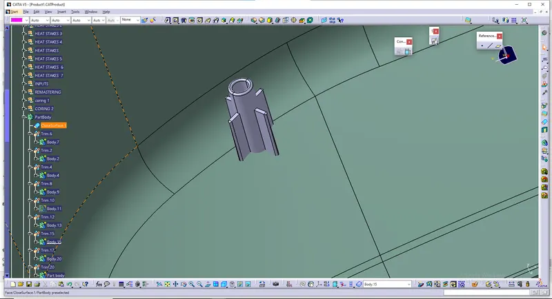
DOG HOUSE:
REMASTERING OF DOG HOUSE:
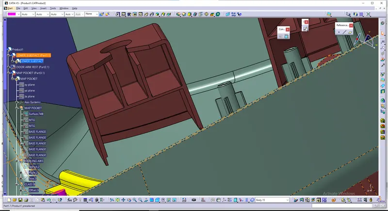
I've remastered the doghouse and placed whereever required
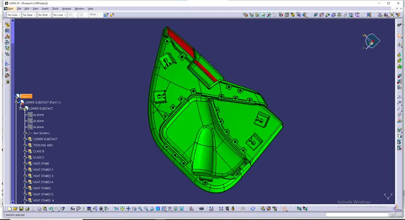
7) Views of the final assembly of Door Trim Panel :
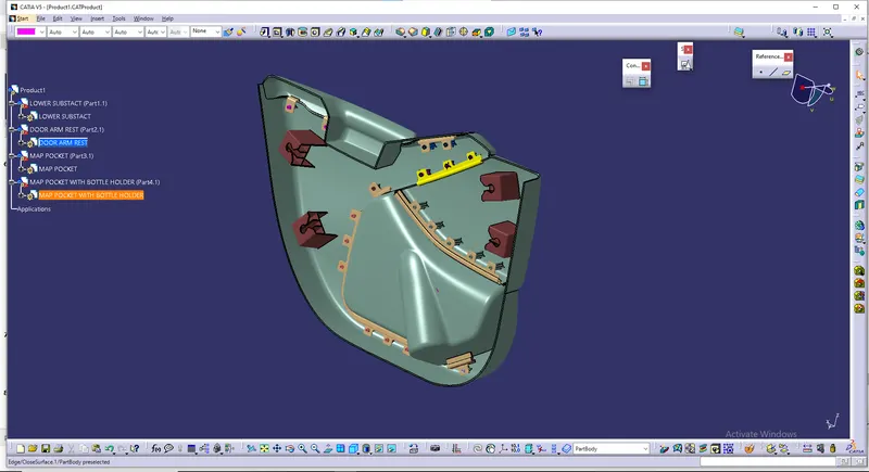
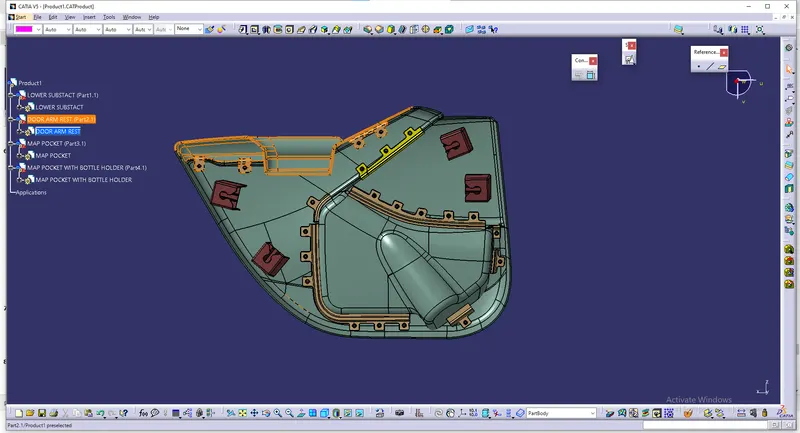
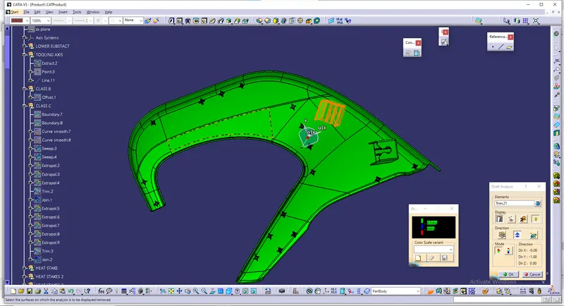
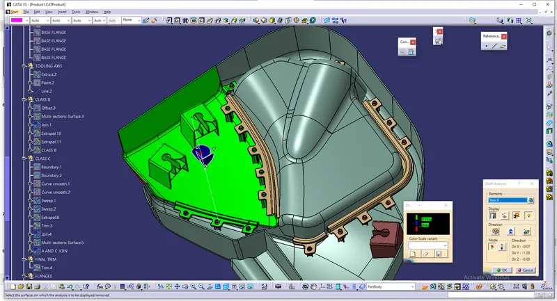
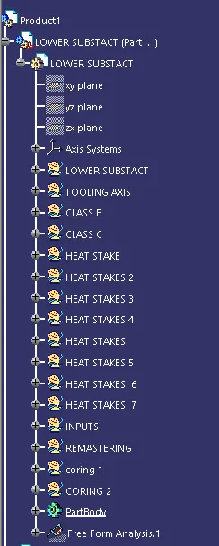
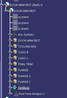
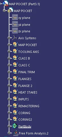
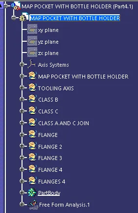
8) Tree Structure :
THERMOSET PLASTIC:
I refer Acrylonitrile Butadiene Styrene (ABS) plastic.
Acrylonitrile Butadiene Styrene (ABS) plastic, is an opaque thermoplastic. It is an amorphous polymer comprised of three monomers, acrylonitrile, butadiene and styrene. ABS is most commonly polymerised through the emulsification process or the expert art of combining multiple products that don’t typically combine into a single product.
When the three monomers are combined, the acrylonitrile develops a polar attraction with the other two components, resulting in a tough and highly durable finished product. The different amounts so f each monomer can be added to the process to further vary the finished product.
The versatility of ABS plastic properties contributes largely to its popularity across several industry sectors. From computer keyboard keys to LEGO, products made from ABS can be found all around the world in multiple domestic, commercial and specialist settings.
Acrylonitrile Butadiene Styrene (ABS):
The acrylonitrile in ABS plastic provides chemical and thermal stability, while the butadiene adds toughness and strength. The styrene gives the finished polymer a nice, glossy finish. ABS has a low melting point, which enables its easy use in the injection moulding process and 3D printing. It also has high tensile strength and is very resistant to physical impacts and chemical corrosion, which allow the finished plastic to withstand heavy use and adverse environmental conditions.
ABS can be easily moulded, sanded and shaped, while its glossy surface finish is highly compatible with a wider range of paints and glues. ABS plastics takes colour easily, allowing finished products to be dyed in exact shades to meet precise project specifications.
Injection moulding process:
Injection moulding is a manufacturing process for producing parts by injecting molten material into a mould, or mold. Injection moulding can be performed with a host of materials mainly including metals (for which the process is called die-casting), glasses,
An Injection moulding mechine:
Injection moulding uses a special-purpose machine that has three parts: the injection unit, the mould and the clamp. Parts to be injection-moulded must be very carefully designed to facilitate the moulding process; the material used for the part, the desired shape and features of the part, the material of the mould, and the properties of the moulding machine must all be taken into account. The versatility of injection moulding is facilitated by this breadth of design considerations and possibilities.
9) CONCLUSION :
Class-B and Class-C Surfaces are created to the given Class-A surfaces. The design of B-side features is done and they are assembled successfully. A detailed report has been prepared and all the part bodies and assembly has been attached to the challenges successfully.