Week 8 - Challenge 2 - Switch Bezel Design
DESIGN AND DRAFT ANALYSIS OF SWITCH BEZEL
OBJECTIVE
The objective of the project is to design the switch bezel and to do a draft analysis for it by creating the required tooling direction with the help of Bisecting method.
MATERIAL USED:-
Material Supplier / Toolmaker: BASF Corp. / Michael Tool & Mold (Windsor) Ltd.
Material / Process: Ultramid A3L PA 6/6 / injection molding
PA6/6
Nylon 6/6 is very easy to modify with fillers, fibers, internal lubricants, and impact modifiers. With the use of fiber reinforcements, the physical strength of nylon 6/6 can be improved five times that of the base resin. The stiffness of nylon 6/6 can be improved up to 10 times. With impact modifiers, the ductility of nylon 6/6 is comparable to polycarbonate. The use of internal lubricants improves on the already excellent wear resistance and friction properties on nylon 6/6. Its versatility allows it to be used in almost any application that requires high physical strength, ductility, heat resistance and chemical resistance
Introduction:
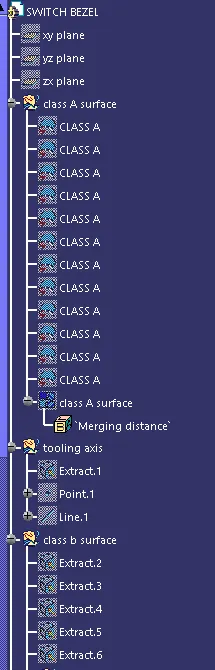
CLASS-A SURFACE: the class-A surface is used in the automotive design industry. it describes the final production surface data for the aesthetic parts.
CLASS-B SURFACE: the class-B surface is the second surface that has a certain thickness from the class-A surface. this surface contains engineering aspects of a model. These must be smooth and "error-free" as well but are not held to the standards that class A surfaces are.
CLASS-C SURFACE: The Class C finish allows more imperfections than Class A or B. Class C is often specified for interior surfaces not readily visible, surfaces that will be covered by another part when assembled, or surfaces.
Design methodology:
Insert the class A surface of the switch bezel in CATIA software.
Determining the tooling axis for the switch bezel
Creation of class B surface.
Creation of class c surface.
Join the switch bezel's class A, class B, and class c surfaces and ensure all the surfaces are closed surfaces.
Use the Close Surface feature to make a solid body from the surface.
finally, Perform the Draft analysis on the switch bezel final plastic component.
DESIGN CONSIDERATION
- Class – A surface should be aesthetically smooth and good.
- Class – B surface should have all the supporting features like ribs.
- Parting Line should coincide with the B surface since flashing couldn’t affect the aesthetic of Class – A.
- Class – C surface should also pass the draft analysis.
PROCEDURE FOR CREATING THE SWITCH BEZEL
- First, the given styling surface is checked for any irregularities and if found any then it is corrected by using Trim, Extrapolate, Split and Join commands.
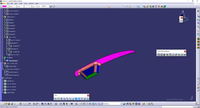
- The below image shows that the Class – A surface is clean and no irregularities present, so let's move on to the next step.
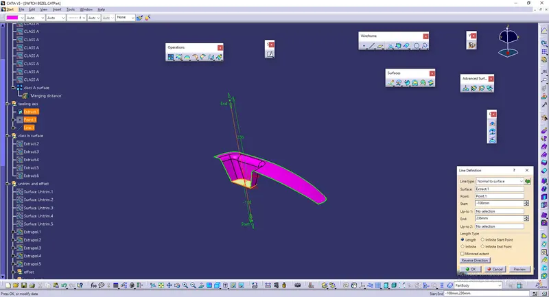
CREATION OF TOOLING DIRECTION
- Considering the Ejection from the cavity of the mould after manufacturing the interior trim (switch bezel) must have the nominal 3-degree draft angle.
- Hence the tooling direction is created by considering the above factor and bisecting method is used.
- The base surface of the class – A was extracted and a point at the centre is created and an axis system was inserted to the point with the current feature is disabled.
- Then, using project intersection along yz plane is created and the two inclined lines were drawn inside the positioned sketch.
- Then bisecting lines with the two inclined lines were drawn.
- Now the same procedure is done along the xz plane but on one side we don’t have inclined lines so the centre point is used to extrude a line along the z-direction and gave a measurement of 5 degrees (Tentatively).
- With these two lines from sketches 1 and 2, the bisecting line is crated and published as Tooling Axis(tooling direction).
CREATION OF CLASS – B SURFACE
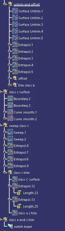
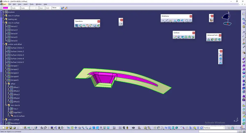
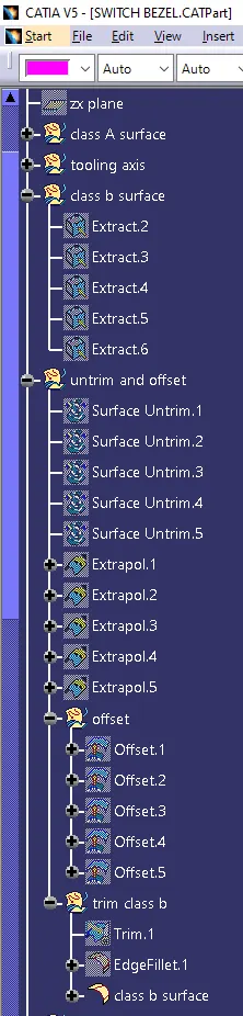
- For creating the class-B surface the required surface except the offset surface have been extracted and then untrimmed all the surface.
- Then all the surfaces have been extrapolated to get intersections between them.
- Since the thickness of the Switch bezel is 2.5mm the B-Surface was offset to 2.5 mm and the required trim operations must be carried out.
- Finally, the required corners have been filleted to 12.5mm (15mm-2.5mm). [ 15mm - fillet value of the A-surface, 2.5mm – Thickness of the component ]
CREATION OF CLASS – C SURFACE
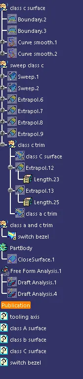
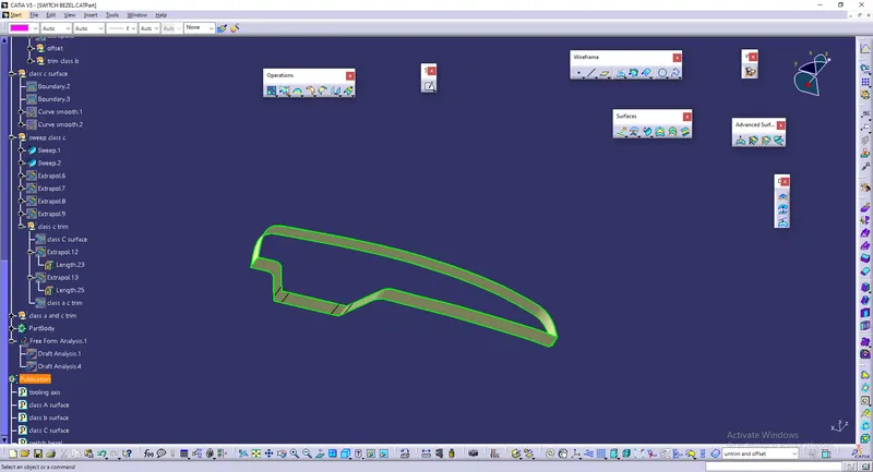
- The required outer edges of the A-Surface were extracted using Multiple Extract. Then for avoiding the patches the curve is smoothened using the Curve Smooth option.
- Then by using the sweep command the surface was created with the following feature controls,
- Profile type – Line
- Subtype – With Draft Direction
- Guide Curve – Smooth Curve
- Draft Direction – Tooling Axis
- Draft Computation Mode – Square
- Angle – 3 Degree
- Angle Sector – Positive Downward (1)
- Length – 20mm
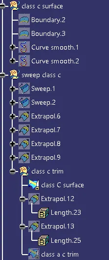
- Then by using extrapolate command the edges were intersected between the surface corners which eases the trimming operation.
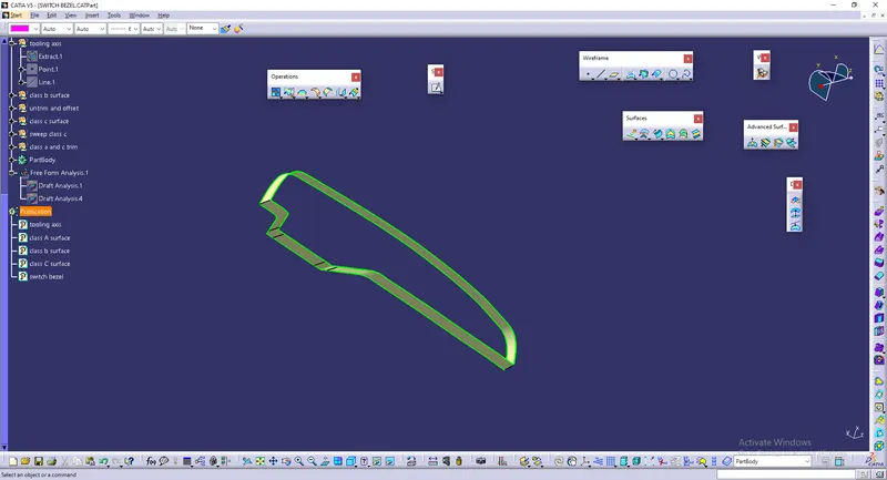
- Now the required portion of the C – surface were trimmed out.
CREATION OF CLOSED SURFACE
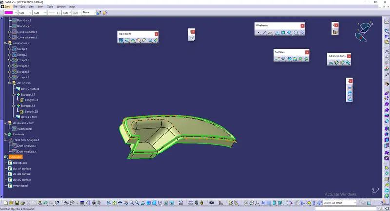
- Now the class – A and Class- C surfaces were joined together by removing the gaps in-between them with the help of extrapolation(tangent continuity) and Trim surface.
- Then the exact surface of the Switch bezel was trimmed from the above-resulted trim surface with the class-B surface.
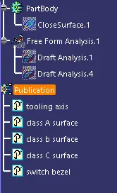
- Then, by defining the part body by using the Closed Surface command
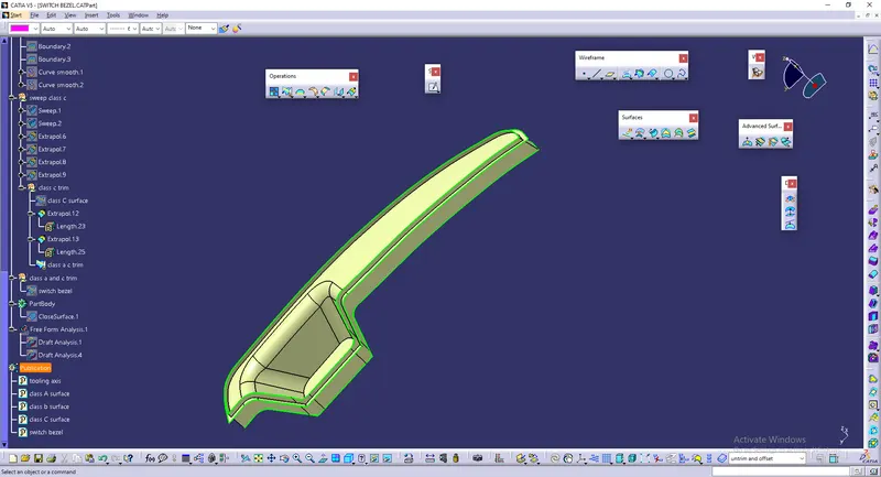 in Part Design, the component's solid body is created.
PROCEDURE FOR DRAFT ANALYSIS
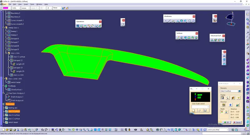
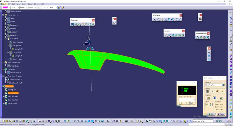
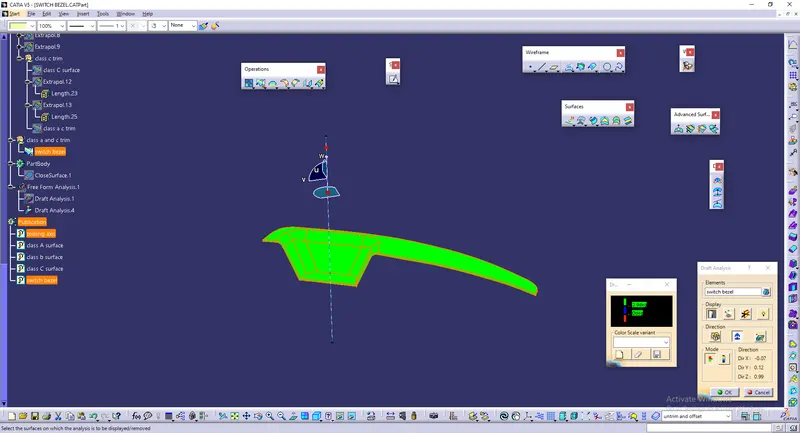
- First the class – A surface is checked before creating the Class –B&C surface and finally the solid body must be analysed. Both can be done by following the below procedures.
- By changing the view mode to custom view parameters – Material mode then the feature draft analysis is enabled.
- Then the compass was activated and placed with the tooling axis by dragging the red pointer and then locked it.
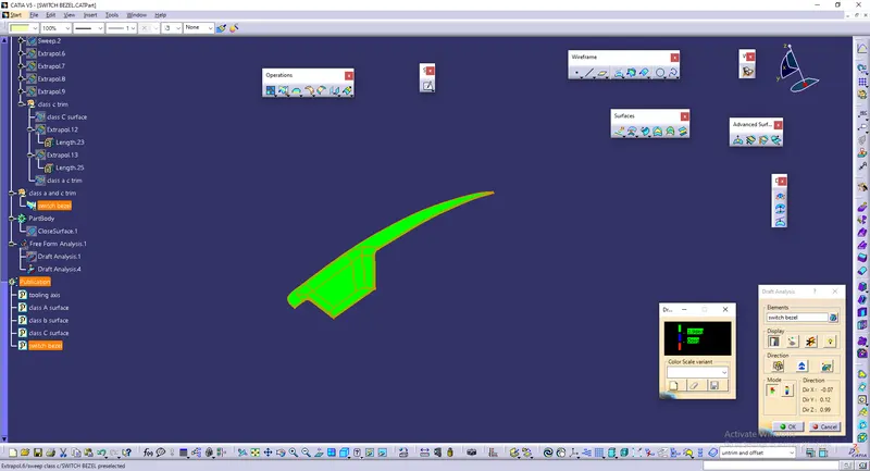
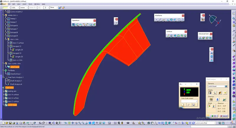
- Then, by selecting the quick analysis mode, the nominal value will be 3 degrees and checked for the component's draft angle.
- The green colour area shows that it satisfies the 3-degree draft angle. If not satisfied then by using the Running point tool the area is measured and then altered to get a successful draft for the created tooling direction.
CONCLUSION
Finally the Class – A, B&C surfaces with the Tooling Direction have been Published and the Switch Bezel is moved on to the designing of the next operation – the creation of B-side features