Week 8 - Challenge 4 - Bumper
Aim: Create the Bumper Plastic component through the given Class-A surface. To begin with, the tooling axis for the given Class-A Surface should be created meeting the requirements of the draft angle and at the end perform the Draft analysis on the model.
Objectives:
- Creation of Tooling Axis.
- Creation of Class B and Class C surface.
- Creating a solid part out of surface modelling
- Draft Analysis of Class A surface and final plastic component.
Tool Used: CATIA V5
MATERIAL USED:
Thermoplastic olefin, thermoplastic polyolefin (TPO), or olefinic thermoplastic elastomers refer to polymer/filler blends usually consisting of some fraction of a thermoplastic, an elastomer or rubber, and usually a filler.
Outdoor applications such as roofing frequently contain TPO because it does not degrade under solar UV radiation, a common problem with nylons.TPO is used extensively in the automotive industry.
Introduction:
CLASS-A SURFACE: the class-A surface is used in the automotive design industry. it describes the final production surface data for the aesthetic parts.
CLASS-B SURFACE: the class-B surface is the second surface that has a certain thickness from the class-A surface. this surface contains engineering aspects of a model. These must be smooth and "error-free" as well but are not held to the standards that class A surfaces are.
CLASS-C SURFACE: The Class C finish allows more imperfections than Class A or B. Class C is often specified for interior surfaces not readily visible, surfaces that will be covered by another part when assembled, or surfaces.
PROCEDURE:
- First, the given styling surface is checked for any irregularities and if found any then it is corrected by using Trim, Extrapolate, Split and Join commands.
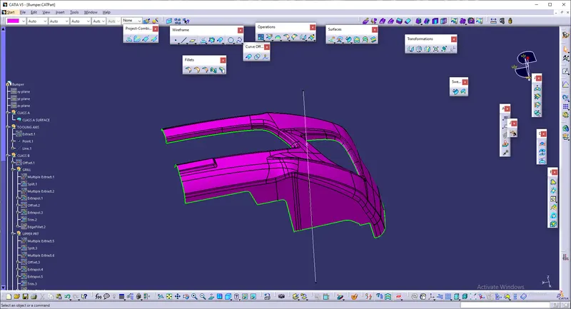
- The below image shows that the Class – A surface is clean and no irregularities present, so let's move on to the next step.
Creating of Tooling Axis:
- Create an intersection of CLASS A surface with ZX plane and from the intersection create the tooling axis as shown below.
Draft Analysis for Surface A:
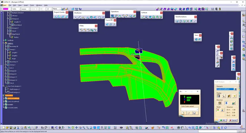
The analysis is done for 3degree draft. So as can be seen all the surfaces are more than 3deg.
Creation of Class B:
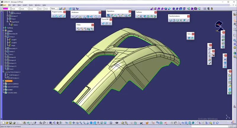
- Now for Class B creation, These surfaces are then offset to the required thickness then the part which is not off setted are removed by using split commands and required potrions are extracted amd off setted.
- After offsetting, all the surfaces are trimmed into the required shape.
- Required fillets are given to the surfaces.
Creation of Class C:
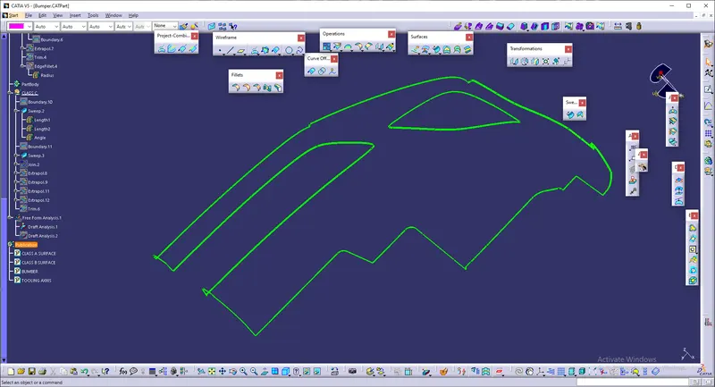
- For creating this surface we have extracted the boundry of Class A using boundry option
- Now this boundry is swept along the draft direction with a 90deg draft with reference surface.
Final Trims:
Class A + Class C:
To make sure that there is not any open boundry between class A and class C, we have used join option to created the single body. This is done to make sure that the parting line doesn't lie between the these two surfaces.
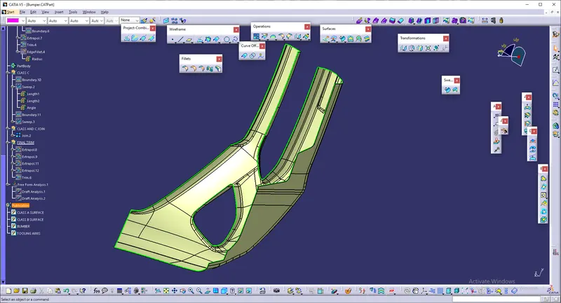
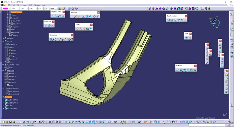
Class A + Class B + Class C:
For this we have trimmed the above shown surface with the Class B surface using trim feature.
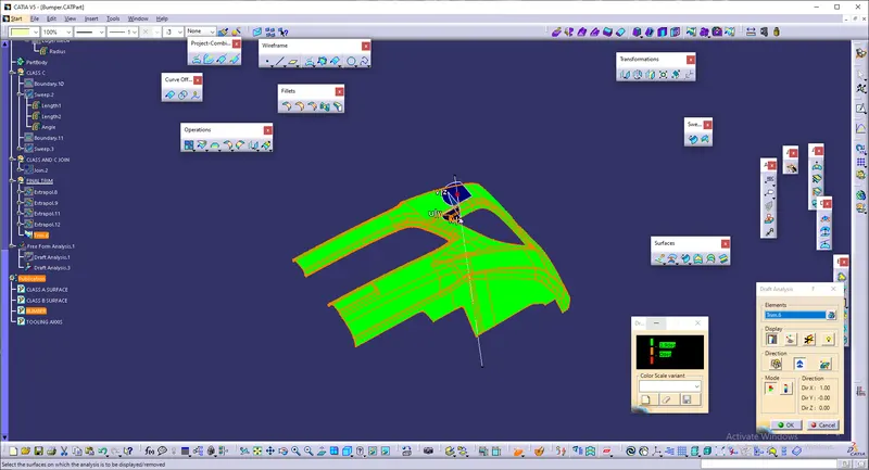
Draft Analysis on the Final Component:
For this analysis, main tooling axis is taken draft reference.
Following results were obtained:
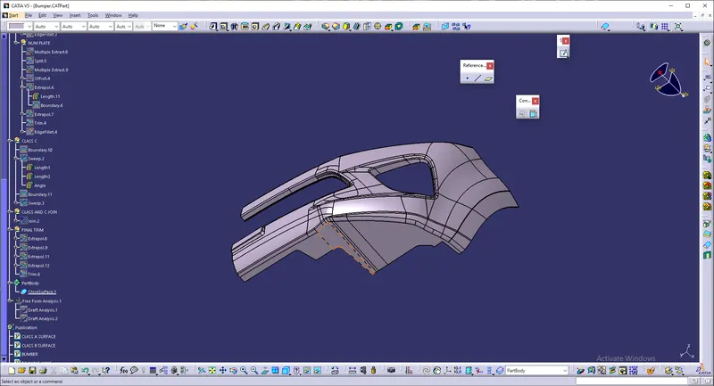
part body:
hence the surface is converted into solid :
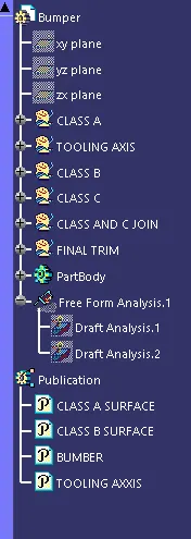
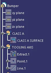
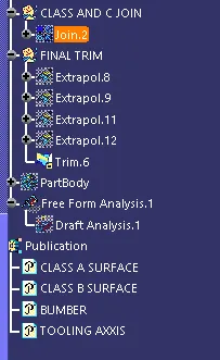
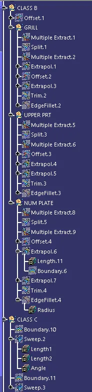
tree structure:
CONCLUSION:
Thus the Bumper Plastic component through the given Class-A surface. To begin with, the tooling axis for the given Class-A Surface should be created meeting the requirements of the draft angle and at the end perform the Draft analysis on the model is done.