Week 11 - Final project
Aim :
To create a CAD model of a side door trim panel from given class A surface .
Objective:
a) Creation of side door trim panle from given class A surface . Apply thickness to it and use attachment features .
b) Creation of flanges and heat stakes from given master sections .
c) Creation of dog house and various attachment features using industry standards
d) Performing draft analysis and ensuring the features and surfaces clear it .
Introduction :
The ten stages in automotive product life cycle developement are listed below .
1)Concept sketch
2) Styling class A
3)Feasilbility check
4)Concept validation
5)New product design
6)Product developement
7) Prototyping
8)Design validation
9)Pilot production
10)Mass production
From the above stages , it isin stage 5 that new product is developed and validated from class A surface . The objective is to design class B and class C surface from given class A surface and create a solid body from it using softwares like CATIA V5, solidworks or solidedge taking into consideration the draft analysis which makes the component suitable for production using injection molding process .
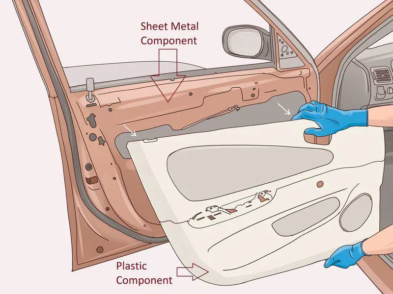
Given below is the procedure to create a new plastic component from given class A surface .
1) Creation of tooling axis
2) Creation of class b surface
3) Creation of class C surface
4) Creation of closed body
5) Draft Analysis .
Draft analysis is done to ensure that the designed part is manufacturable based on the draft conditions applied. It is done to ensure the proper ejection of the component from dies(for metals) or molds(for plastics). The basic idea is to ensure that the tooling axis has to be created in such a wat that it has no parallel surface profiles of the component so that the ejection of the components can be ensured . Tooling axis is the axis along which cavity and core are closed and opened .
The main components of interior door panel of a car consists of the following parts .
1) Arm rest
2) Map pocket (Consists of upper and lower part)
3) Upper substrate (Not given in the current model)
4) Lower substrate .
Step by step procedure
1) Creation of tooling axis
To create tooling axis , we must import the model into catia as a product .
File=>open=>browse=> MASTER SECTION DEVELOPEMENT.igs file .
Given class A surface
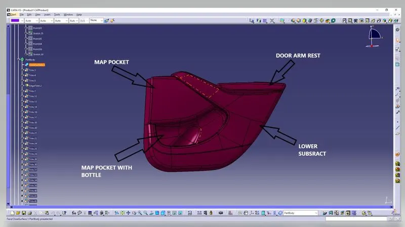
Rear side of the class A with master section
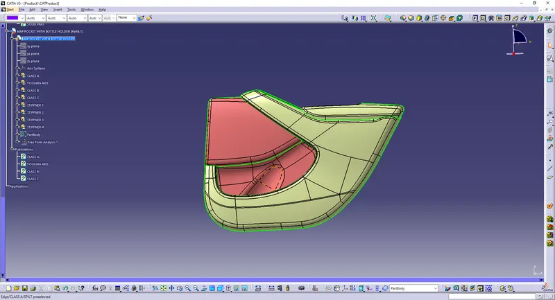
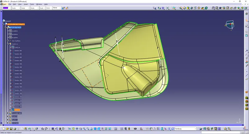
There also provided the master section are shown as a image .
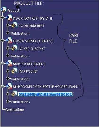
Create a product file and copy each component into different part files and name the accordingly .
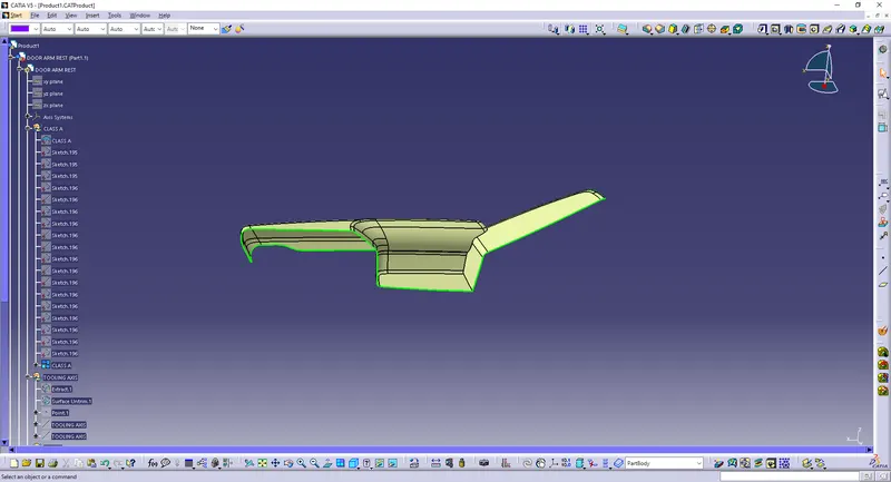
Creation of Tooling axis for Arm Rest
1) We have split the arm rest into 2 parts for simplicity of creation.
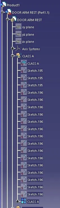
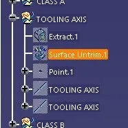
The parts were named as arm rest part 1 and arm rest part 2 respectively
Procedure for tooling axis creation
Step 1: Insert a geometrical set . Extract the base surface and create a point at its center using point on surface option from point tool. Look for suitable axis to create a tooling axis so that all faces clear tooling .
Step 2: Create an axis system without current option ticked at the above point. Create a position sketch with zy plane from axis system and above point as reference point.
Step 3: Use intersect 3d objects option from project tool to create 2 lines by selecting a suitable plane(zy). Now create 2 lines which coincide with lines on both sides of the projection point . Create a line using bisect option .Allign the line in required axis direction.This is our Y tooling axis .
Step 4: To create tooling axis about x direction, create a position sketch with xz plane as reference plane and projection point as the first point we created . Use cut section tool and create an intersection using projection tool . Now create a line that coincides with this line .
Step 5 : Draw a line from origin in horizontal direction and create and angle constraint of 5 degrees. Use bisect option to create a line between that above lines . This is out X tooling axis .
Step 6 : Create a new line using bisect option between X tooling and Y tooling line . this is our required Tooling Axis , Name this as tooling axis and publish it .
Procedure to check for Draft analysis
1)Once the tooling axis is created , publish it and the component using Publication from tool option .
2)Insert Feature draft analysis option from insert tool bar
3) Change the view option to customize view parameters and click on material option under shading .
4) Now click on the axis option from Draft analysis tools , allign it with tooling axis and click on lock option to lock it .
5) Change draft angle value to 3 degree . Click on quick analysis mode to display feature according to given color scale . Check from all views to ensure the draft analysis is cleared .
6) Since the created tooling axis does not clear the draft analysis at the created axis , click on the lock axis button to unlock it . Now rotate the tooling axis by left clicking on the top round portion of the axis system . Rotate the axis till maximum clearance is obtained . Now right click on the axis and click lock current axis .
7) Create a line using the initial axis origin and this axis using point and direction (using compass direction) option . This is our required tooling axis .
8) Now if we check for draft analysis, we can observe that the ribbed area has not yet cleared draft analyisis. Hence we need to create a side core tooling axis . To do this , create a line using point and direction option with Y direction .
9) Repeat steps 1 to 5 to ensure the remaing portion which was not cleared using Tooling axis has been cleared using this axis .
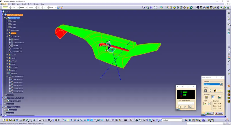
Similarly created tooling axis using same procedures for all other components .
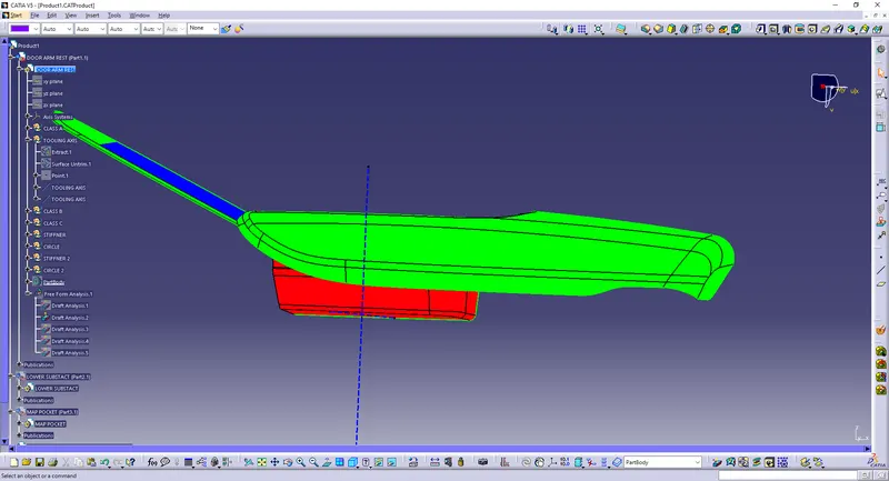
Tooling axis for Arm rest 2
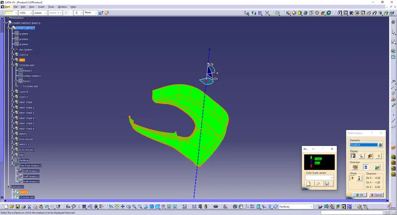
Tooling axis for lower substrate
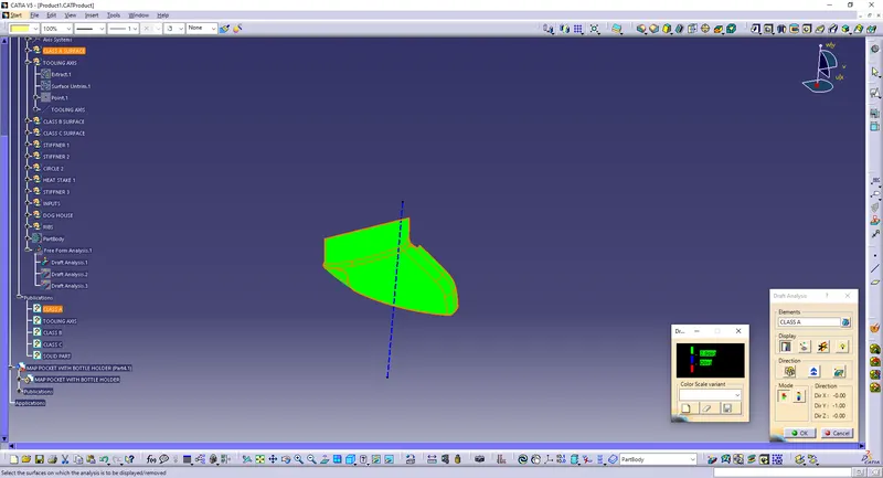
Tooling axis for Map pocket upper
Tooling axis for map pocket lower
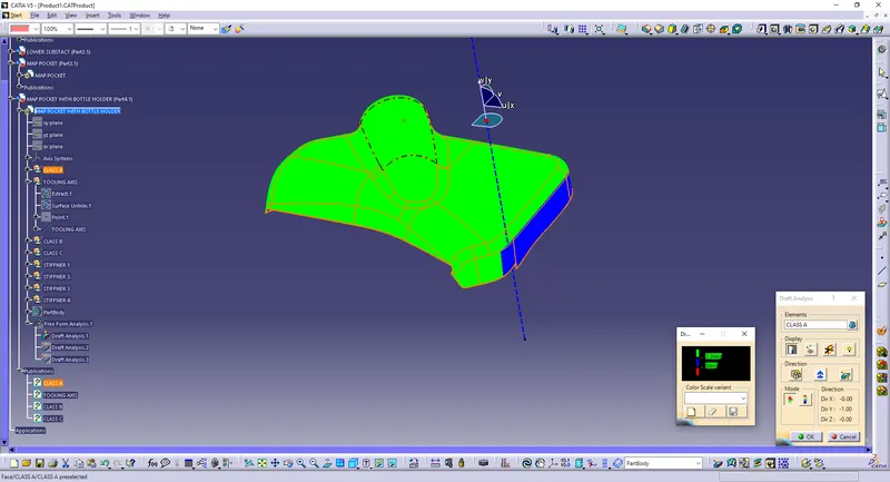
Here we can observe that regions in blue colour has a 0 degree draft angle . This would lead to ejection problems while molding process . Hence the class A surface has to be modified to meet draft requirements Hence we have created tooling axis for all components .
2) Creation of class B surface
Procedure to create class B surface for Lower substrate .
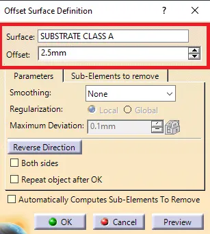
Step 1: Use offset tool with a distance value of 2.5mm to create offset of class A surface .
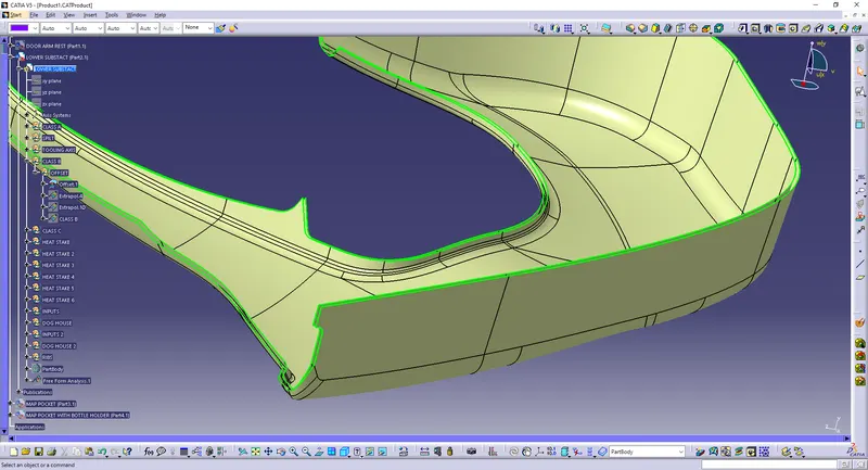
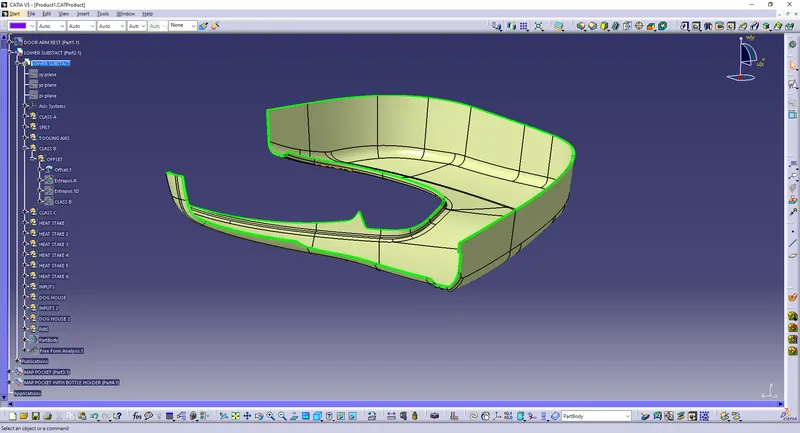
Step 2: After offsetting , extrapolate tool was used to extend all the edges of this surface . This is done to ensure that the parting line comes at B surface .
Step 3: In areas where extrapolate was not possible (Fillet or cusped surfaces) multisection surface option was used .
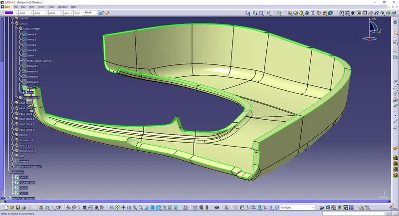
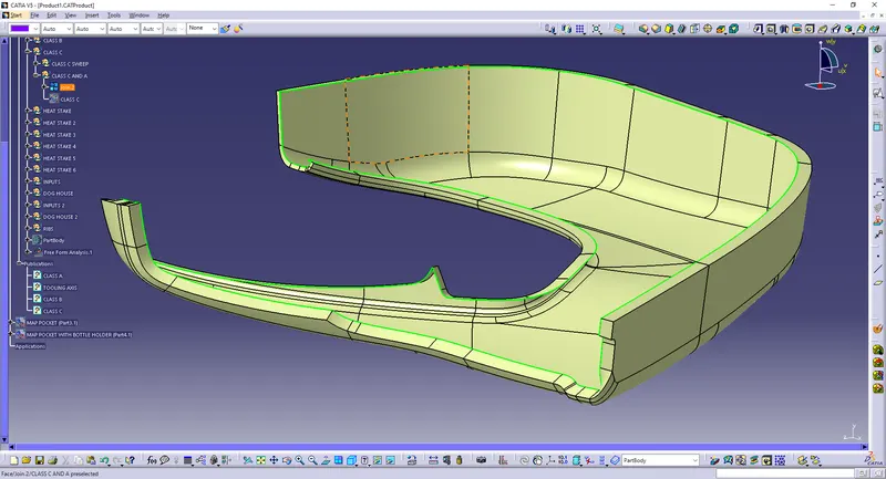
Step 4: Join all the extrapolated surface and multi section surfaces to obtain a single surface .
Hence the class B surface was created for lower substrate .
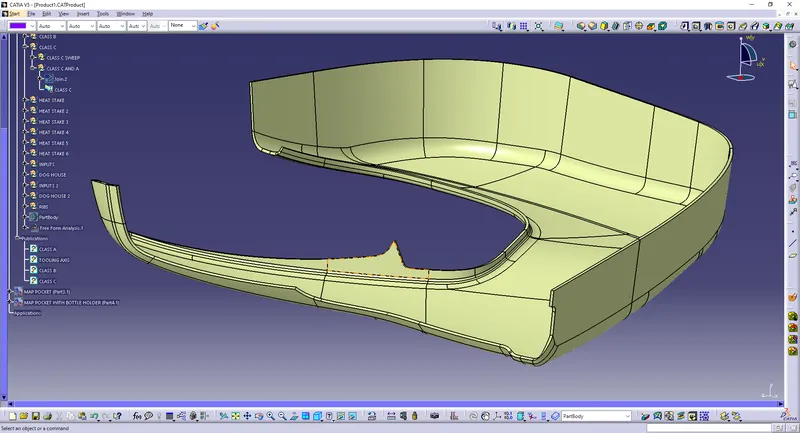
Similarly , class B surface was created for other components .
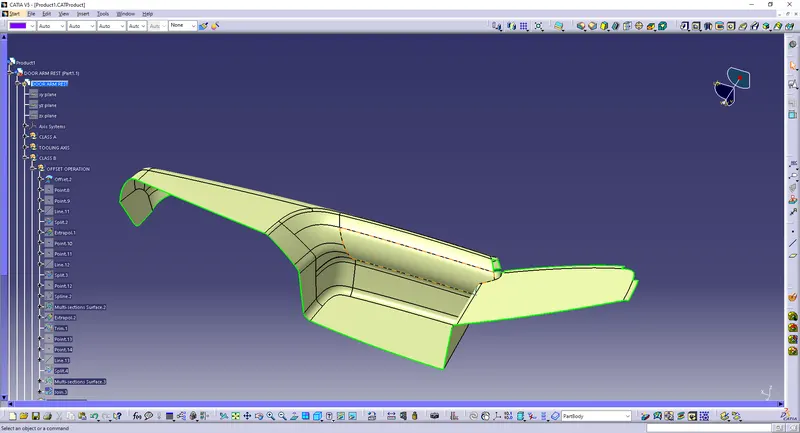
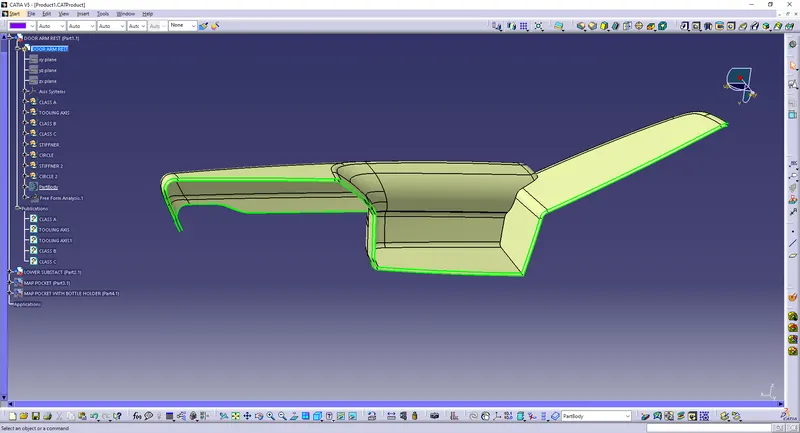
Tree stucture for lower substract are given below,
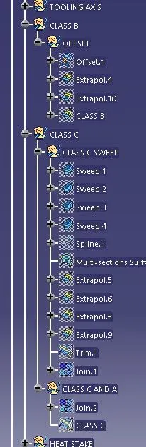
Class B surface of arm rest PART 1
Class B surface of map pocket upper
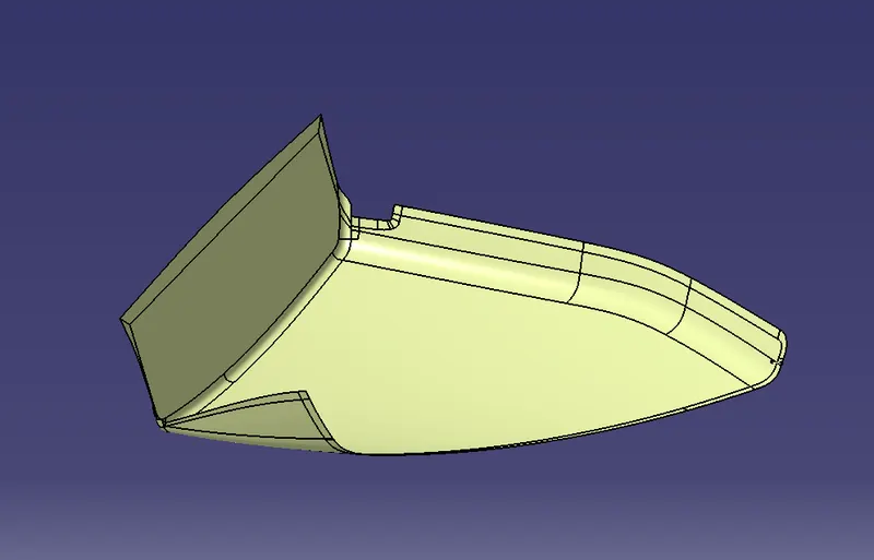
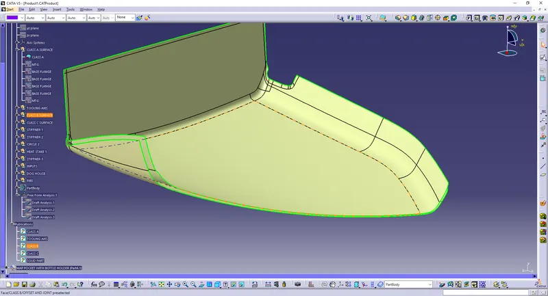
Class B surface of map pocket lower
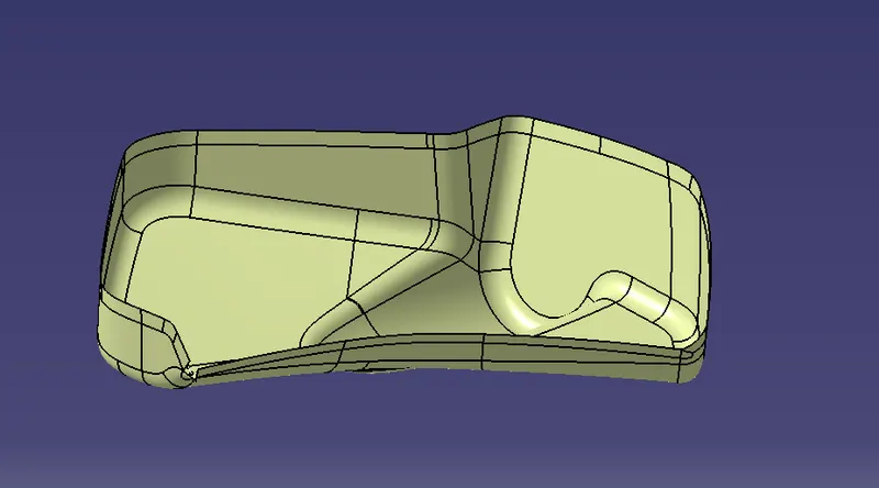
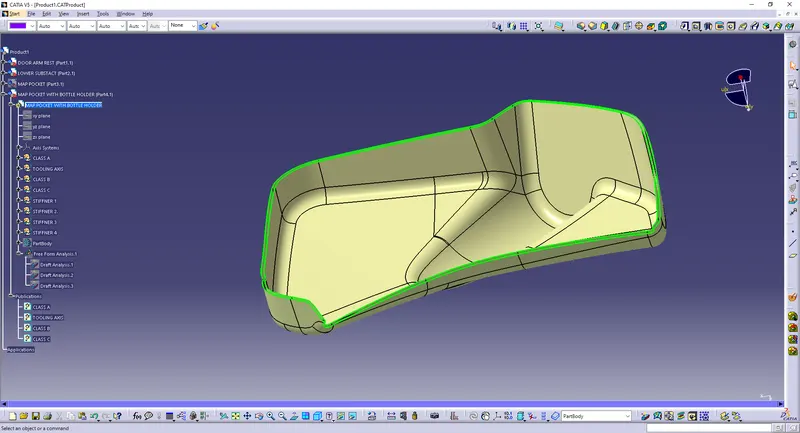
Hence class B surface for all components were created .
3) Creation of Class C surface
Procedure for creation of class C surface for Upper map pocket
Step 1: Use sweep command to create a new surface an an angle with respect to a surface . This angle is dependant on draft angle for free edges and ususally 90 degree for mating surfaces .
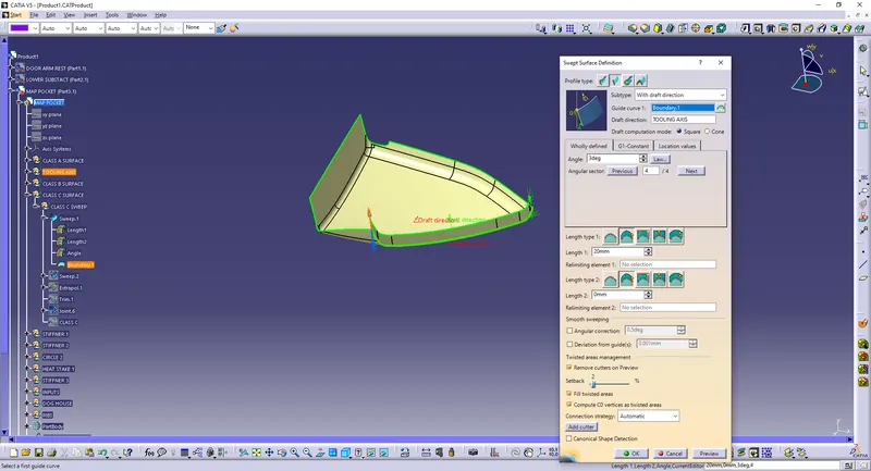
Step 2: In areas where sweep is not possible , use Multi section surface to create a new surface .
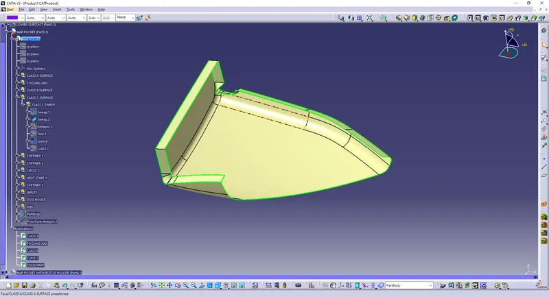
Step 3: Join all surfaces to obtain C surface.
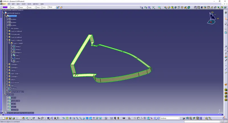
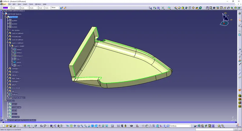
Hence C surface was obtained for upper map pocket
Similarly C surfaces were obtained for all other components .
C surface for Lower map pocket .
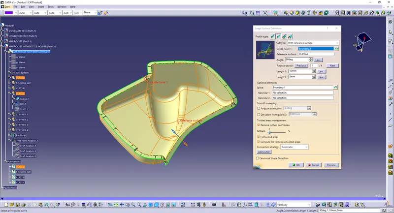
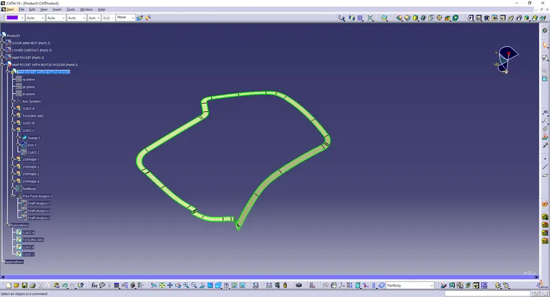
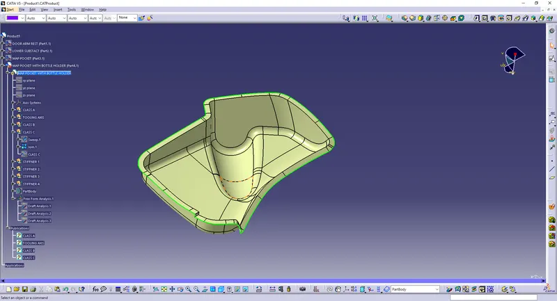 Class C surface for Arm rest part 1
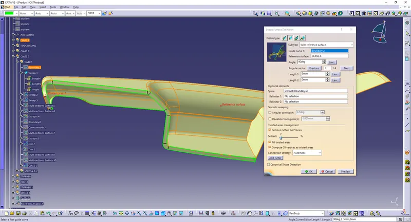
Class C surface for Arm rest part 2
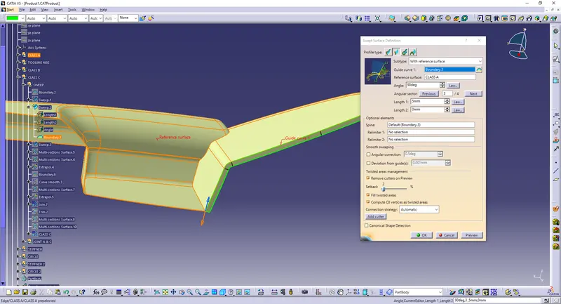
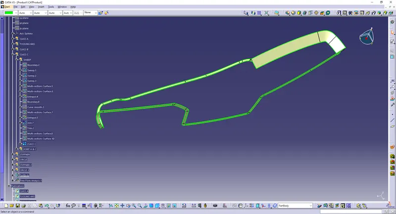
Class C surface for Lower substrate
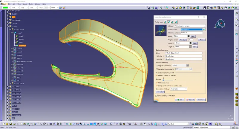
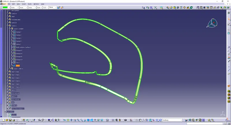
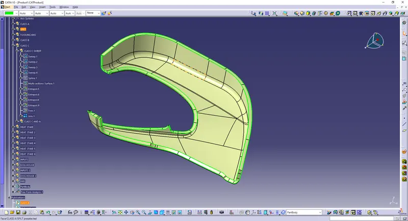
Hence class C was created for all components .
4) Creation of closed body
Procedure for creation of closed body for lower map pocket .
Create the Class C surface and then use trim option to join above trim with class B .
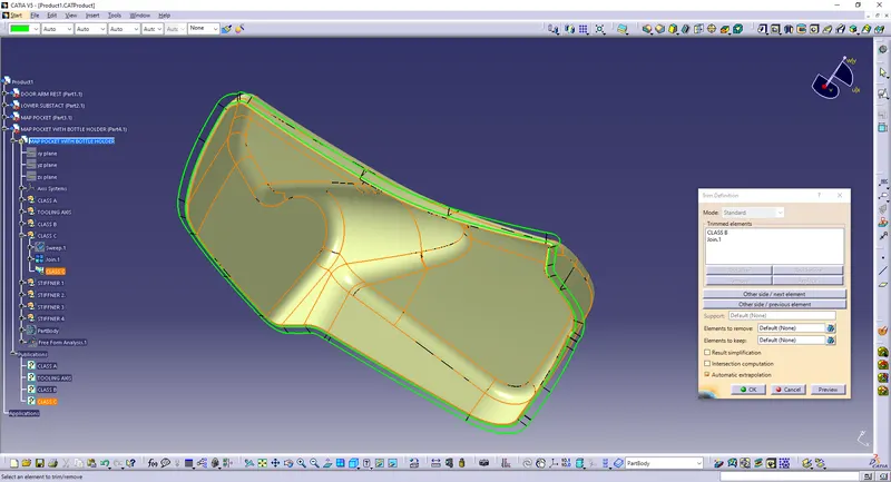
Hence we have obtained closed body .
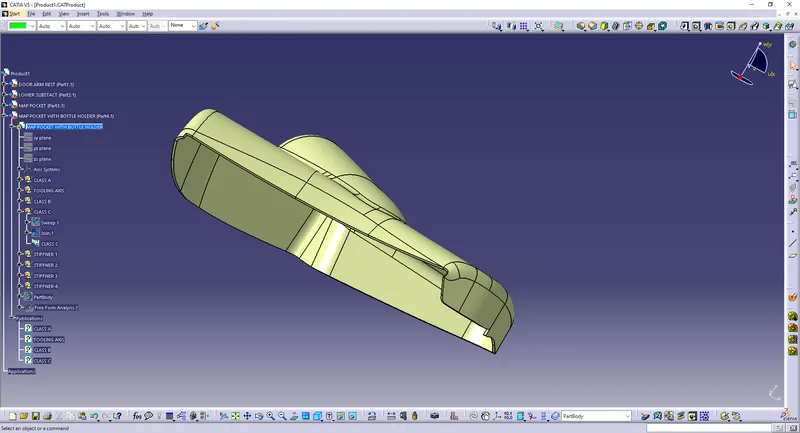
Similarly closed body was obtained for all other parts
Closed body for upper map pocket
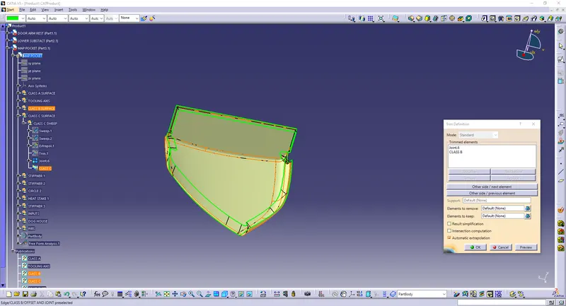
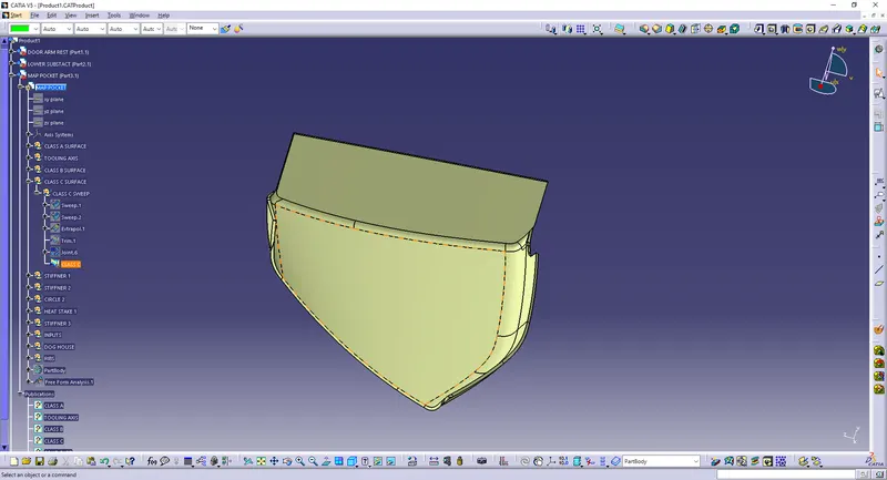
Closed body for Lower substrate
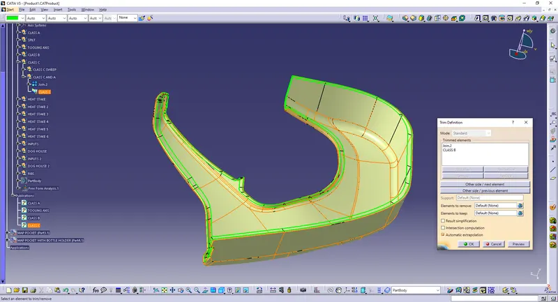
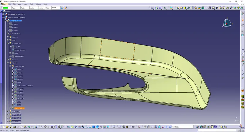
Closed body for Arm rest part 1
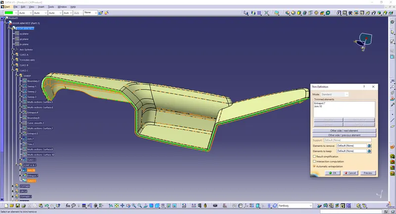
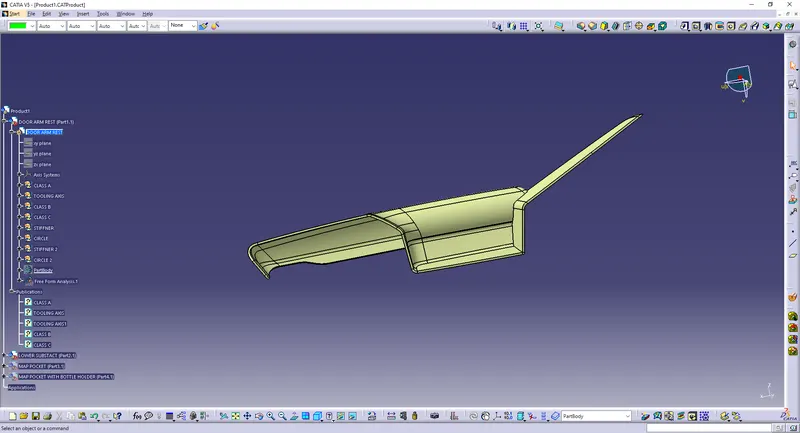
Hence we have created closed body for all parts and thus we have created solid bodies from them .
5) Draft Analysis
Procedure to check Draft analysis for Map Pocket with Bottle Holder .
1)Once the tooling axis is created , publish it and the component using Publication from tool option .
2)Insert Feature draft analysis option from insert tool bar
3) Change the view option to customize view parameters and click om material option under shading .
4) Now click on the axis option from Draft analysis tools , allign it with tooling axis and click on lock option to lock it .
5) Change draft angle value to 3 degree . Click on quick analysis mode to display feature according to given color scale . Check from all views to ensure the draft analysis is cleared . Click ok to complete the Draft analysis mode.
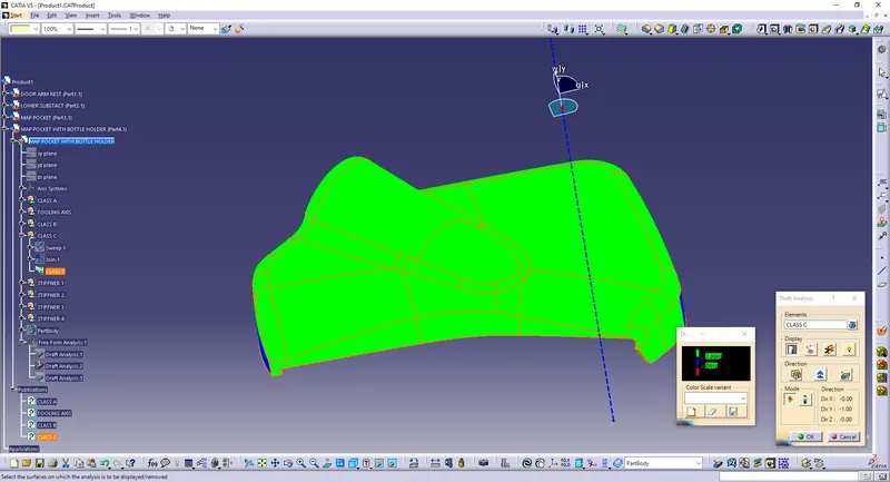
Draft analysis for Door Arm Rest
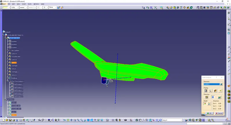
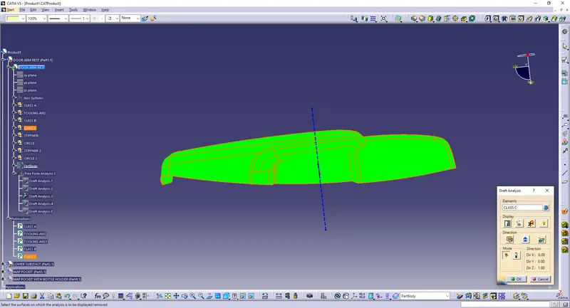
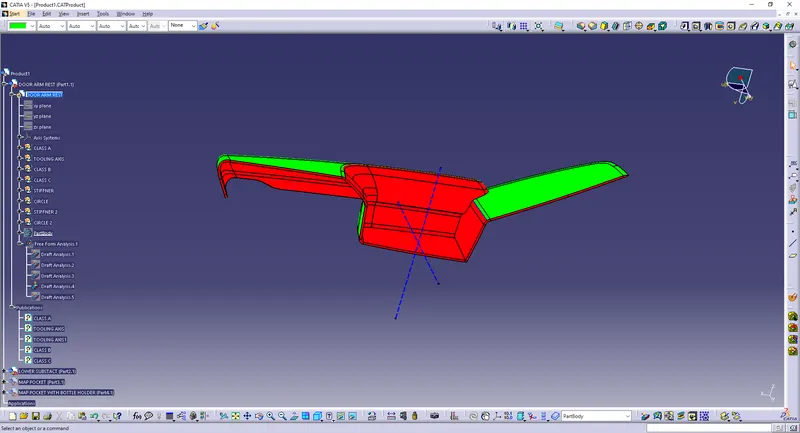
Draft Analysis for Lower Substact .
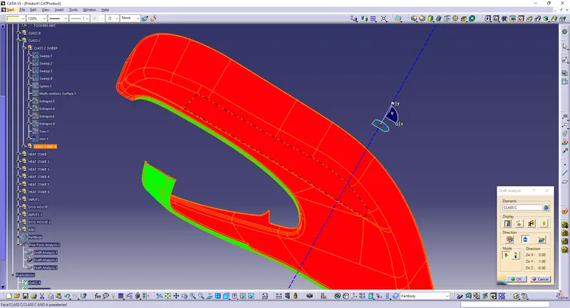
Draft Analysis for Map Pocket .
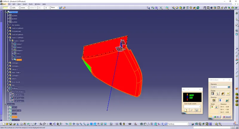
Hence we have completed first part of the project and have obtained closed body for all the parts clearing draft analysis
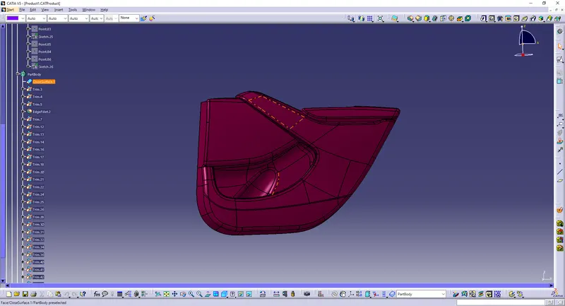
PART 2 : Attachment of flanges using given master sections .
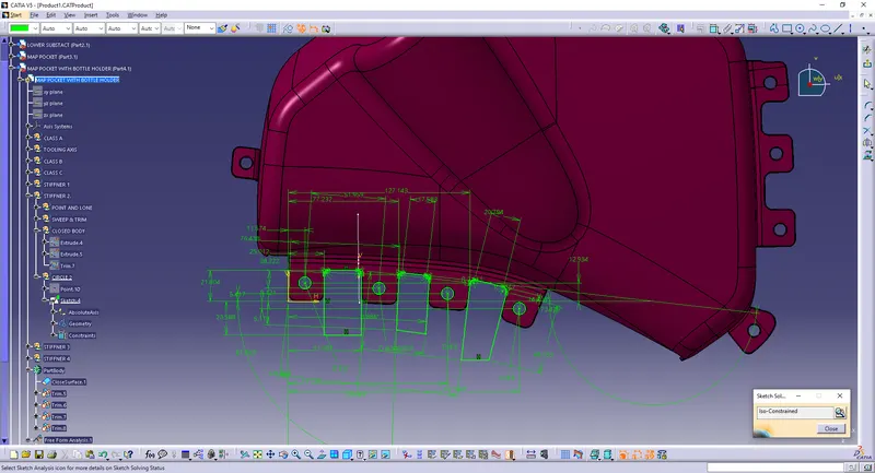
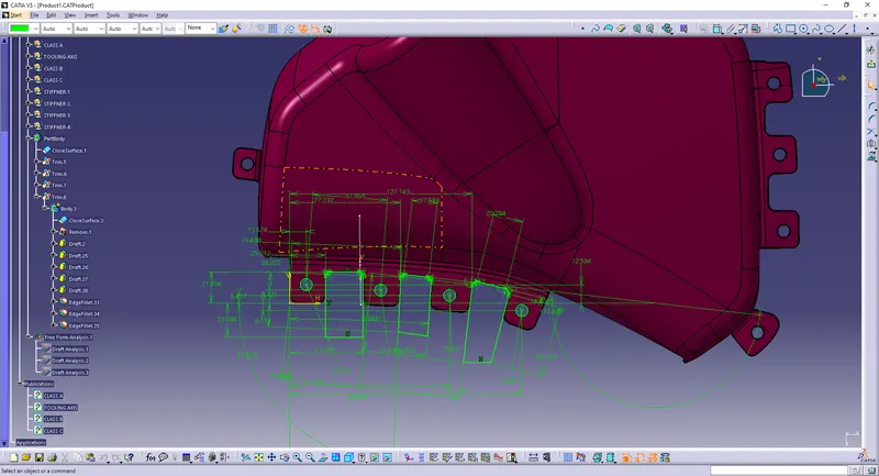
Procedure to create flanges and heat stakes for Arm rest part 2 from given master sections .
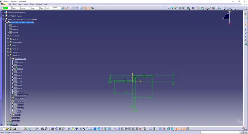
Step 1: Use multiple extract to obtain required guide curve and sweep profile for flange top surface .
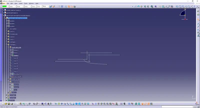
Step 2 : Use sweep option to create a surface from below obtained multiple extracts .
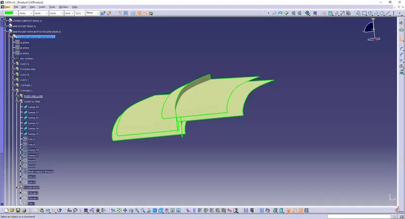
Step 3 : Use extrapolate to extend the surface according to master section and create a solid body in a new body . Create holes and flat surfaces for heat stake .
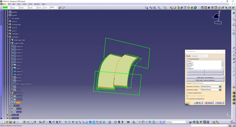
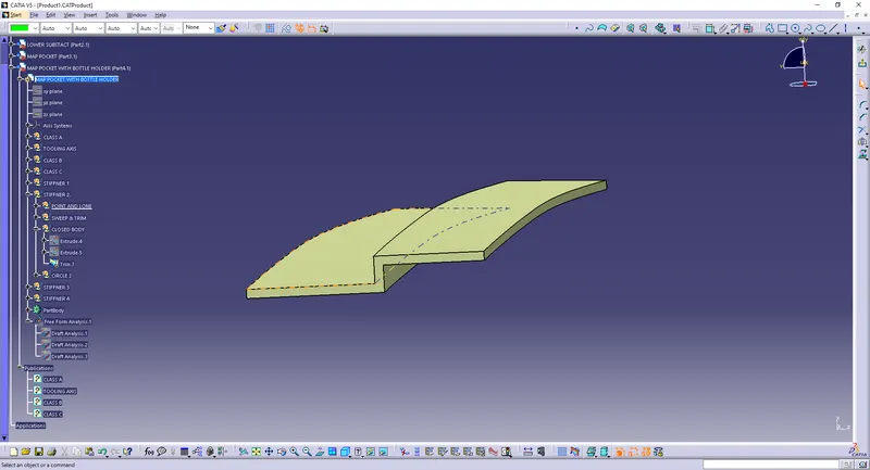
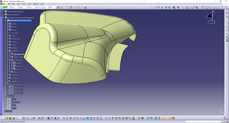
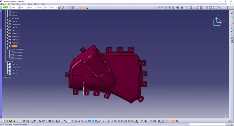
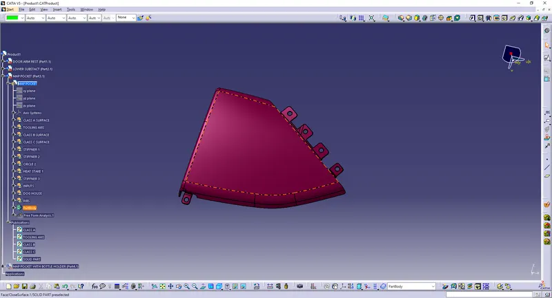
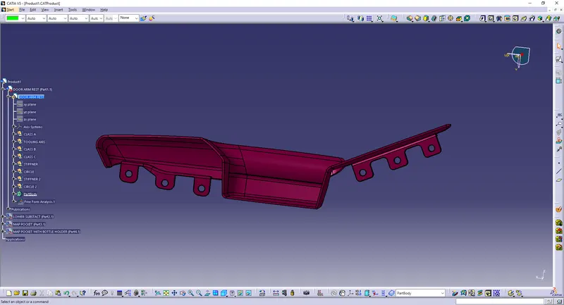
Step 4:Heat stake was created from padding a sketch created from a point obtained from master section.
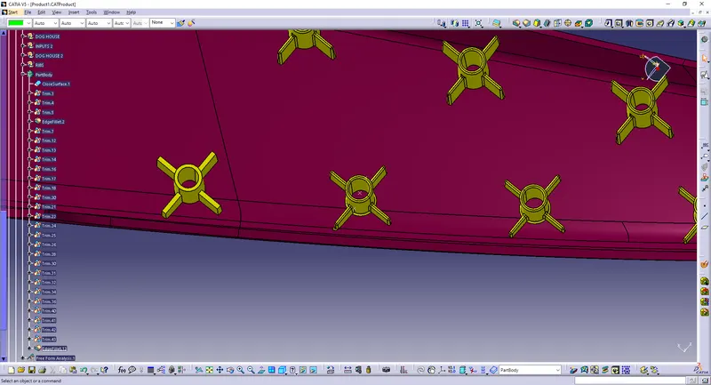
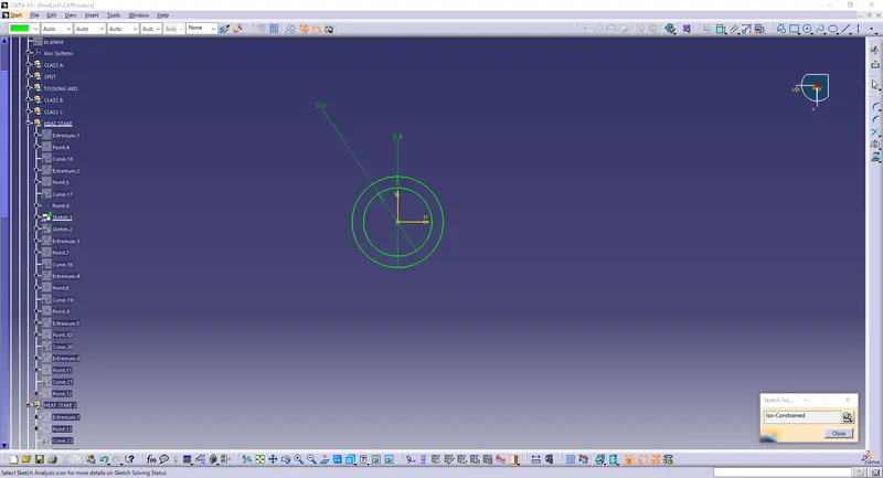
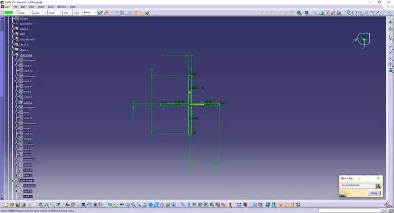
Step 5: Stake support was created using padding the multiple extract from master section and thickening it .
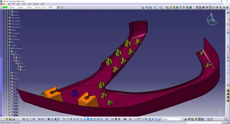
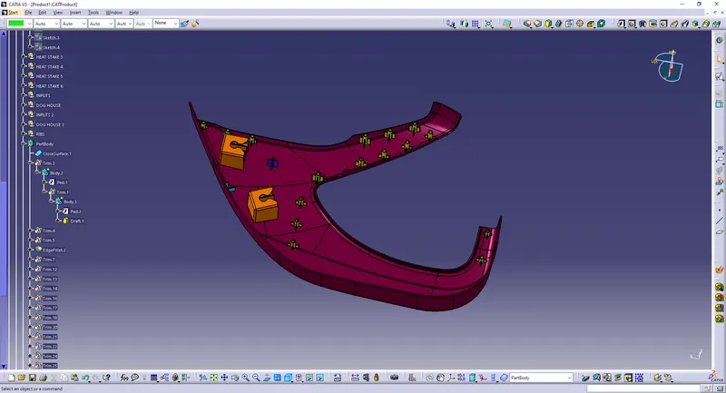
Similarly features were created on all parts according to master section .
Flanges on upper map pocket
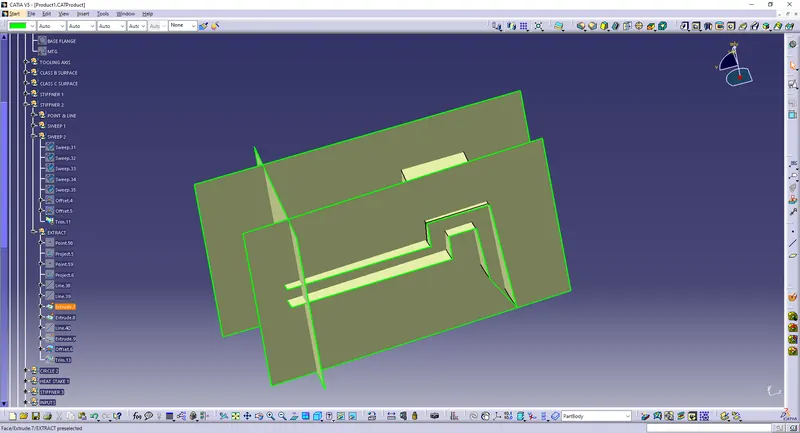
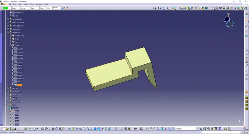
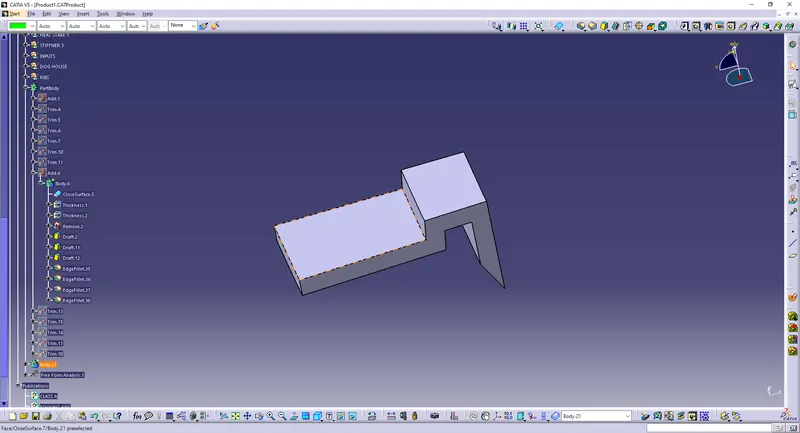
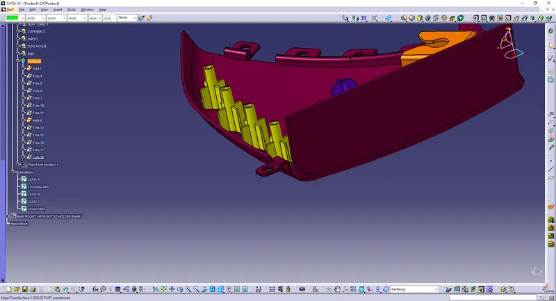
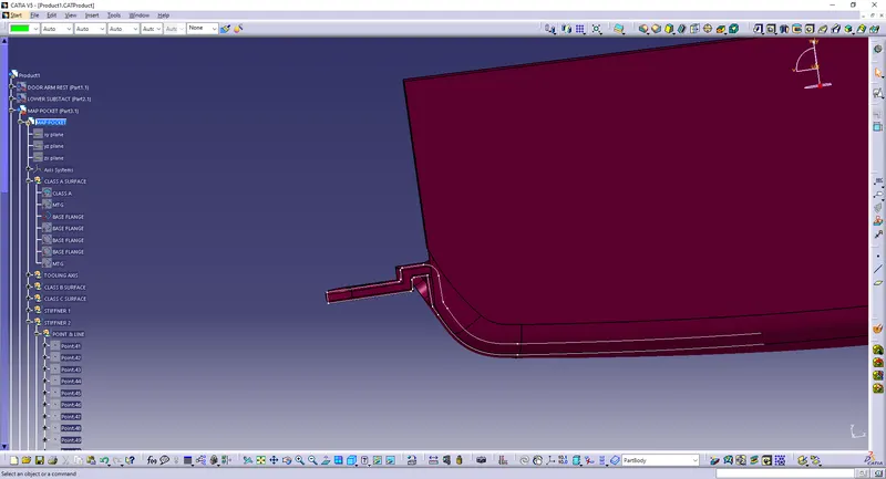
Hence we have made features according to master section.
3) Creation dog house by the form of "REMASTERING" and additional attachment features according to industry standards.
Procedure to create dog house on lower substrate .
DOG HOUSE
Dog house is an engineering feature used in plastic design. Dog houses are used as support feature. Sometimes other engineering features like snaps, locators, screw bosses are mounted on them to increase their strength.
Dog houses are subjected to draft analysis to prevent breakage of the component during ejection from the mould cavity. Dog house and oher engineering components are built on the B-surface.
Step 1: Create a point on required location and a plane from it . Create a sketch with base sketch for dog house by the form of "REMASTERING".
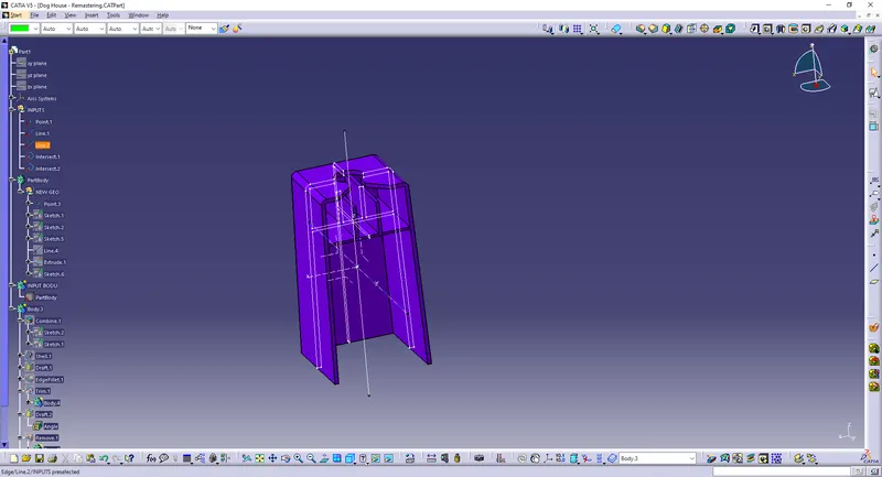
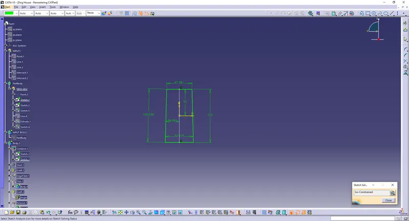
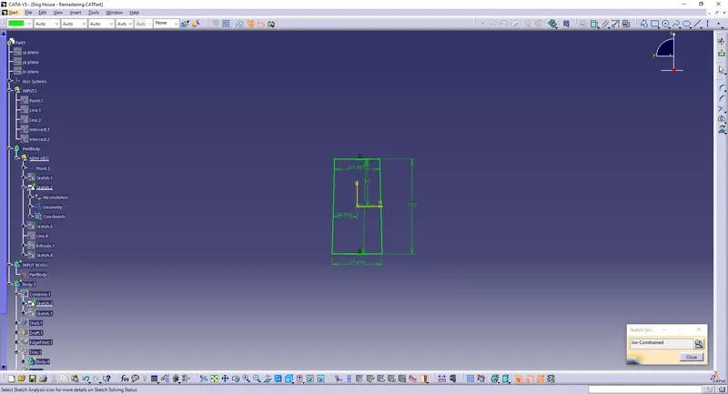
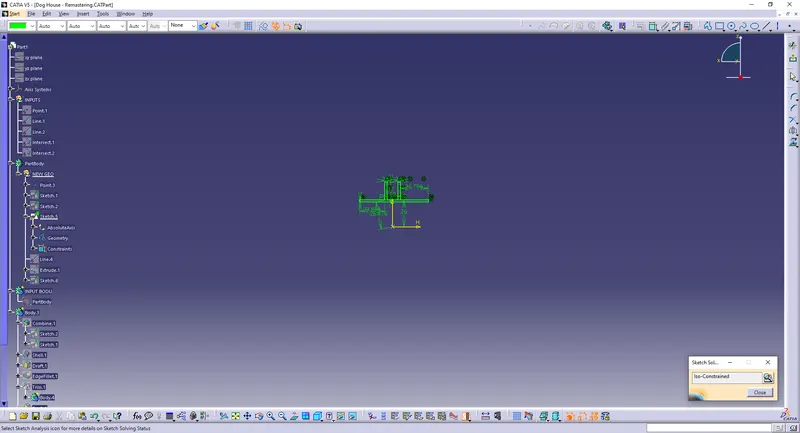
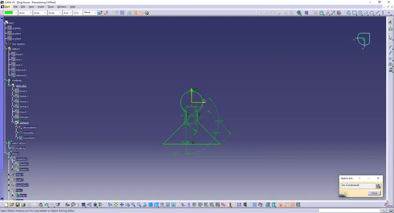
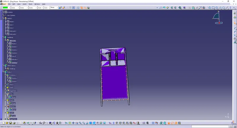
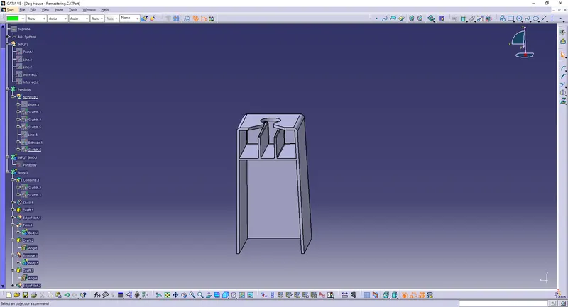
Use boolean operation union trim to obtain required design.
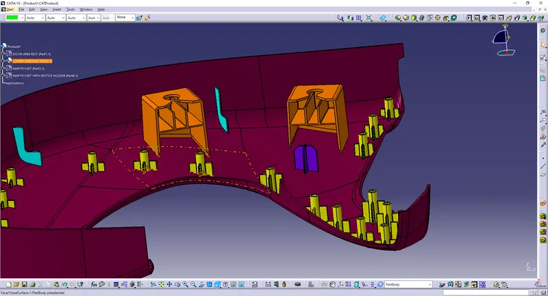
Thus we have created dog house .Now we have made complete dog house with ribs . Use translate option to position it in required locations . 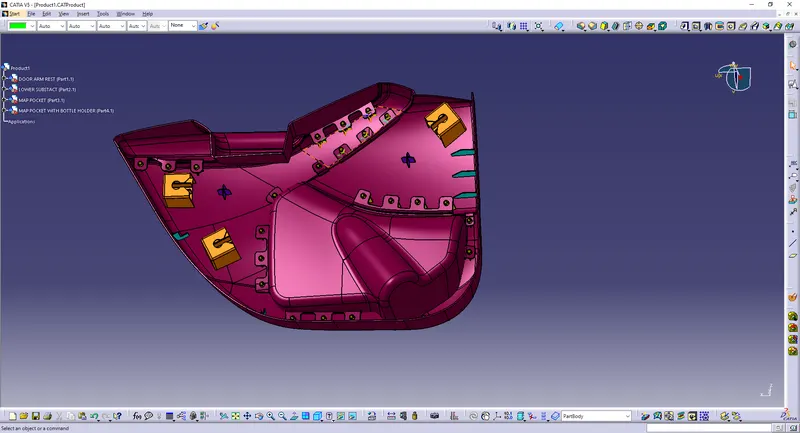
Procedure to create ribs on Heat stakes
Step 1: Create a sketch with center as centre of heat stake inner circle .
Step 2: Use pad option to create solid body
Step 3: Use boolean opetaion union trim to obtian required ribs.
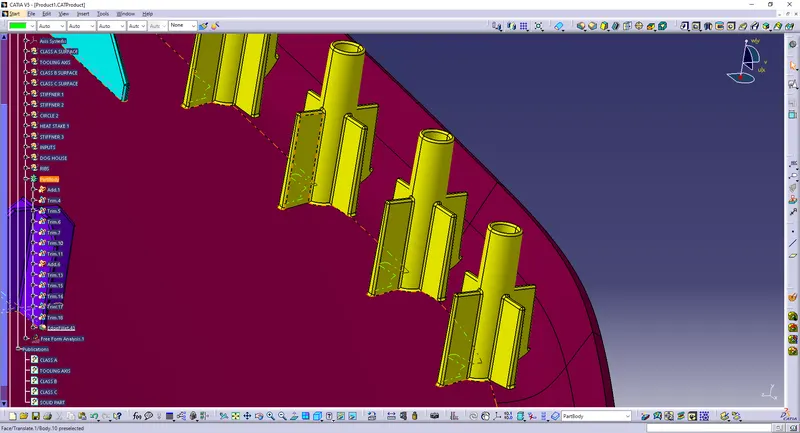
Procedure to create ribs on lower substrate
Ribs
Ribs are thin wall protrusions that extend perpendicularly from a wall or plane. They are usually found in clusters offering support to a plane that would have otherwise been too thick, but can also be stand-alone support for a single wall. They are commonly used to provide additional support and strength to a part. Thickness and location are essential to rib design.
Step 1: Create a sketch and create a surface . Use thick surface option to obtain ribs in required shape .
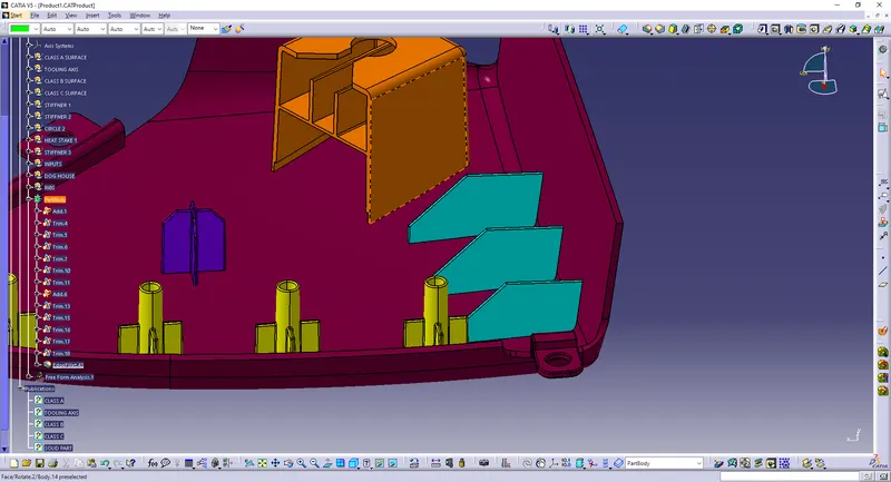
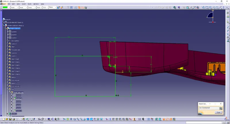
Locaters
Now we will see how the plastic part is fixed onto the other plastic part. The door applique is fixed on to the door surface with the help of locators and heat stakes. Every component in space has 12 degrees of freedom. So these locators and heat stakes restrict all these degrees of freedom.
Locators are 4-way locators. The locators will follow the rib design guidelines and will be given a minimum draft of 0.5 degrees and a minimum fillet of 0.2mm and an entry chamfer of 3mm. This entry chamfer is given so that the locators can mate with the other part easily.
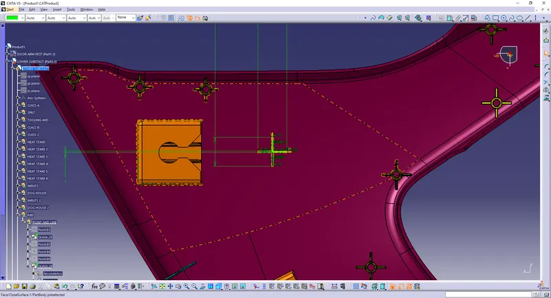
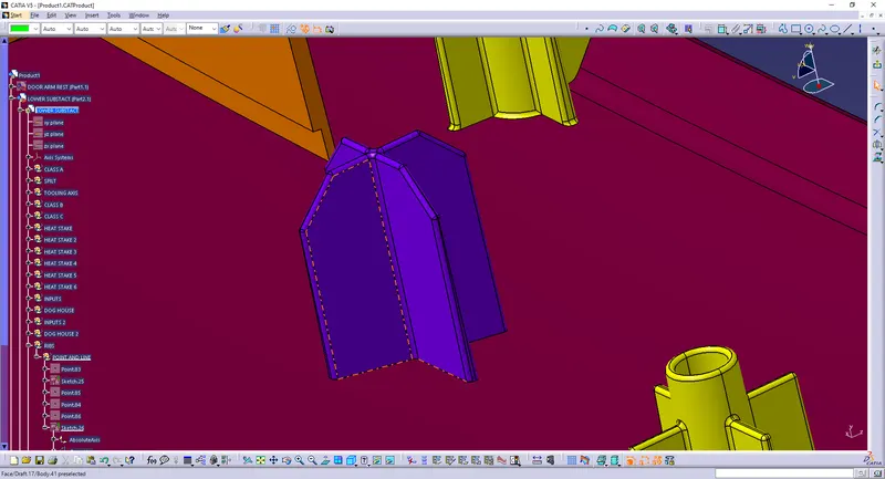
Step 2:Use Translate option to place ribs wherever required.
Step 3: Use Boolean operation union trim to trim it with lower substrate main body .
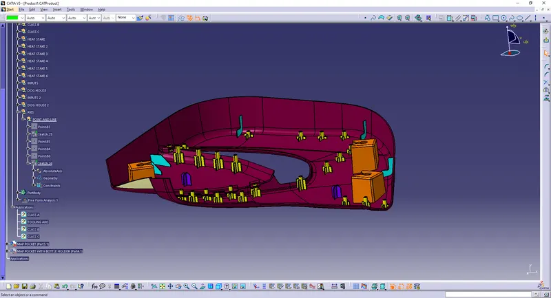
Create heat stakes and flanges at required locations using above mentioned procedures to obtain complete substrate body . Apply draft on all required surfaces and fillets on all straight edges.
Final Upper map pocket
Final Lower map pocket
Final Hand rest part 1
Draft analysis for Completed parts
1) Door arm rest:
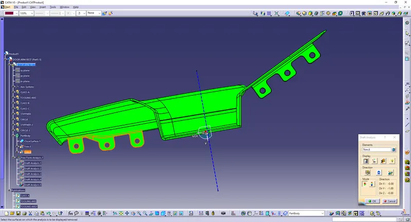
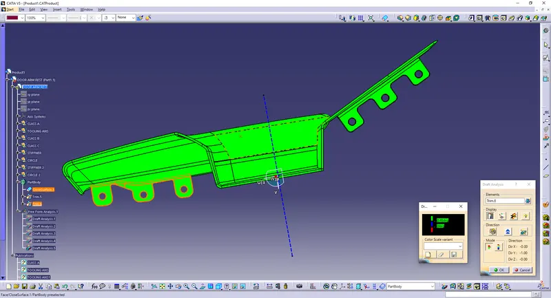
2) Lower Substrate:
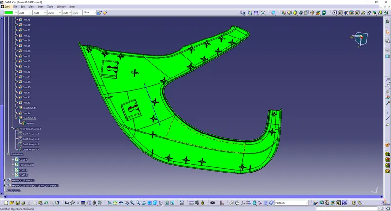
3) Map pocket:
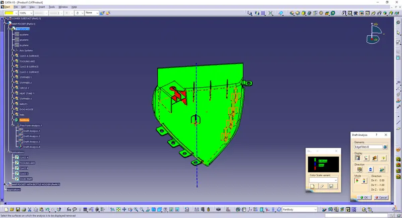
4) Map Lower pocket with water bottle:
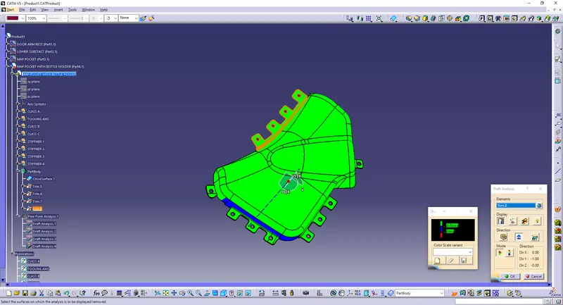
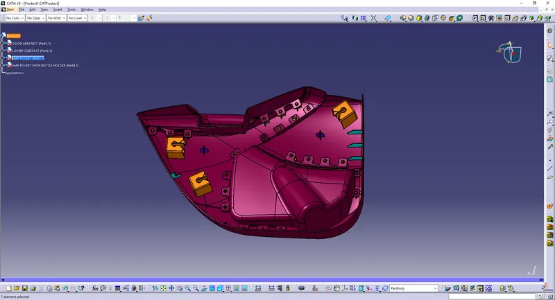
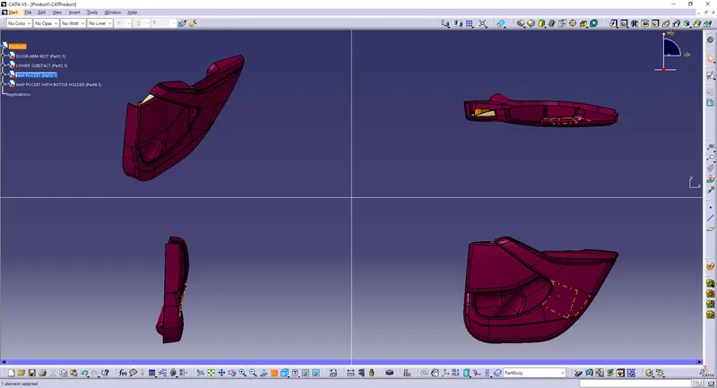
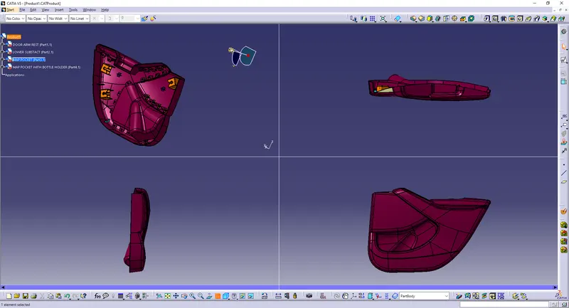
Completed model after all attachment features
THERMOSET PLASTIC:
I refer Acrylonitrile Butadiene Styrene (ABS) plastic.
Acrylonitrile Butadiene Styrene (ABS) plastic, is an opaque thermoplastic. It is an amorphous polymer comprised of three monomers, acrylonitrile, butadiene and styrene. ABS is most commonly polymerised through the emulsification process or the expert art of combining multiple products that don’t typically combine into a single product.
When the three monomers are combined, the acrylonitrile develops a polar attraction with the other two components, resulting in a tough and highly durable finished product. The different amounts so f each monomer can be added to the process to further vary the finished product.
The versatility of ABS plastic properties contributes largely to its popularity across several industry sectors. From computer keyboard keys to LEGO, products made from ABS can be found all around the world in multiple domestic, commercial and specialist settings.
Acrylonitrile Butadiene Styrene (ABS):
The acrylonitrile in ABS plastic provides chemical and thermal stability, while the butadiene adds toughness and strength. The styrene gives the finished polymer a nice, glossy finish. ABS has a low melting point, which enables its easy use in the injection moulding process and 3D printing. It also has high tensile strength and is very resistant to physical impacts and chemical corrosion, which allow the finished plastic to withstand heavy use and adverse environmental conditions.
ABS can be easily moulded, sanded and shaped, while its glossy surface finish is highly compatible with a wider range of paints and glues. ABS plastics takes colour easily, allowing finished products to be dyed in exact shades to meet precise project specifications.
Injection moulding process:
Injection moulding is a manufacturin process for producing parts by injecting molten material into a mould, or mold. Injection moulding can be performed with a host of materials mainly including metals (for which the process is called die-casting), glasses, elastomers, confections, and most commonly thermoplastic and thermosetting polymers. Material for the part is fed into a heated barrel, mixed (using a helical screw), and injected into a mould cavity, where it cools and hardens to the configuration of the cavity.After a product is designed, usually by an industrial designer or an engineer, moulds are made by a mould-maker (or toolmaker) from metal, usually either steel or aluminium, and precision-machined to form the features of the desired part. Injection moulding is widely used for manufacturing a variety of parts, from the smallest components to entire body panels of cars. Advances in 3D printing technology, using photopolymers that do not melt during the injection moulding of some lower-temperature thermoplastics, can be used for some simple injection moulds.
- High rigidity.
- Good impact resistance, even at low temperatures.
- Good insulating properties.
- Good weldability.
- Good abrasion and strain resistance.
- High dimensional stability.
- High surface brightness and excellent surface aspect.
An Injection moulding mechine:
Injection moulding uses a special-purpose machine that has three parts: the injection unit, the mould and the clamp. Parts to be injection-moulded must be very carefully designed to facilitate the moulding process; the material used for the part, the desired shape and features of the part, the material of the mould, and the properties of the moulding machine must all be taken into account. The versatility of injection moulding is facilitated by this breadth of design considerations and possibilities.