Week 8 - Challenge 3 - Coin Holder Design
AIM:
To Create the Coin Holder Plastic component through the given Class-A surface. To begin with, the tooling axis for the given Class-A Surface should be created meeting the requirements of the draft angle and at the end perform the Draft analysis on the model.
Take the Thickness of the component to be 2.5 mm
OBJECTIVE
Conduct a Draft Analysis for the Coin Holder Plastic by determining the appropriate Tooling Axis and check if all the features are above the Nominal Drafting.
CLASS A SURFACE:
In automotive design, a class A surface is any of a set of freeform surfaces of high efficiency and quality. Although, strictly, it is nothing more than saying the surfaces have curvature and tangency alignment – to ideal aesthetical reflection quality, many people interpret class A surfaces to have G2 (or even G3) curvature continuity to one another.
CALSS B SURFACE:Class B surfaces are the secondary surfaces that you can see sometimes, but are less important, such as the inside of your glovebox, ash tray, etc.. These must be smooth and "error-free" as well, but are not held to the standards that class A surfaces are.
CLASS C SURFACE:Class C surfaces are the backside surfaces that can have tool marks, flash and other imperfections without hurting appearance, function, etc.
CREATED CLASS A SURFACE:
Class A Surface is all ready created by the designer, there are shown below as an image.
Steps followed
The class A surface is checked for the connectivity of the surface and ensure it is completely joined and there will be no gap between the surfaces.
If it is not join together make it with a minimum tolerance of 0.001 to 0.003 and check for connectivity of the surface.
Connectivity of the surface can be done by two ways by join method and by boundary method.
Split the surfaces into multiple profiles then Identify the surface where it is not possible to create a tooling axis and check on which direction is best fit for tooling axis and then define the tooling axis and draft direction.
Here for defining the tooling axis first we have created a point at middle of the base surface and create an axis with respect to that point then define the tooling axis using the intersect method by creating a bisecting line.
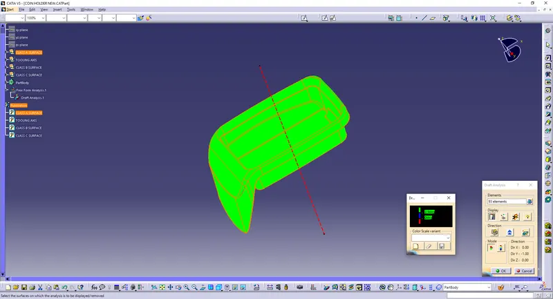
Then do a draft analysis on the class A surface and identify the draft angle then give the nominal value for the draft.
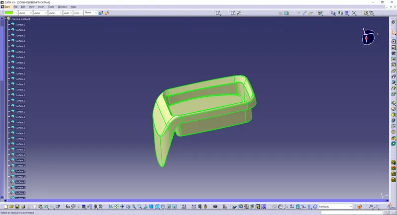
Fig.1.


fig. 2 & 3.
JOINT TOOL:
Using the joint tool just joint the Class A Surface after that extract tool is used for to create a tool axis if the selected surface as show in fig 4.
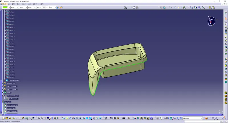
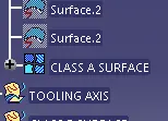
Fig.4
Tooling Axises:
Class-A surface is first analyzed to create tooling axis or tooling direction that molds pull apart in injection molding. Tooling direction is vital for plastic product design as it decides direction for mold separation.
Steps followed for creation of tooling axis:
- Reference point is first created on extracted surface.
- New axis system is deployed to plot clearance lines.
- The X direction and Y direction along the class A were used to create tooling axis
- Two clearing lines were bisected to form Tooling axis.
- Graphic properties of tooling axis were change before publishing.
- Show in fig. 5, 6, & 7
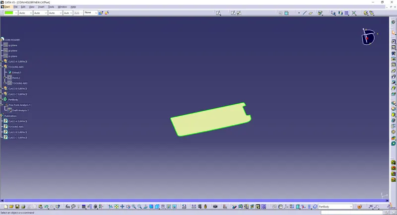
Fig 5.
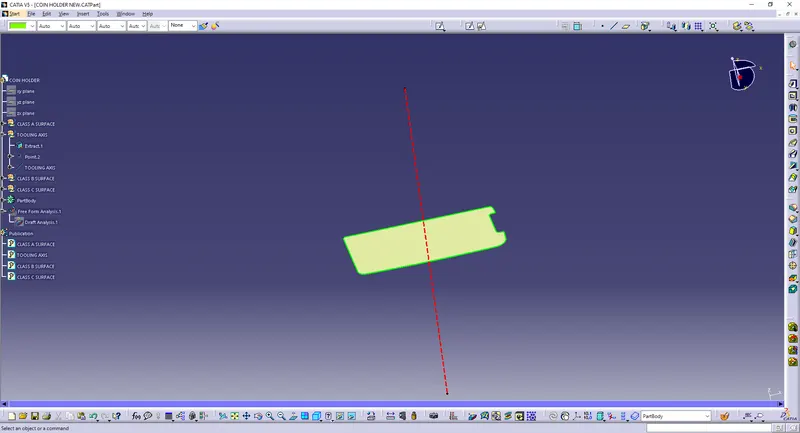
Fig 6.
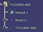
Fig 7.
Tooling axis creation:
The direction in which the mould open and closes is called the tooling axis direction.
Check the connectivity of the surface and ensure there will be no gap between the surfaces and then define the tooling axis.
While creating a tooling axis please ensure to give the tooling axis on a flat length surface or the surface which have a hole on it.
Create a point on the middle of the base surface by using point on the surface command then create a intersection for the surface and extract the reference lines which will be helpful for creating the dummy tooling axis using the intersect method by creating a bisecting line..
Use the line command and draw the lines which is aligned with the extracted lines and extended it to the required length.
Bisecting method:
Identify on which plane we have to do more operations and create the plane or axis on the component area define it on the dummy tooling axis direction.
Intersect the class A surface with that plane then we will get a intersection sketch. Look for the profile (inclined line) which will create a problem and extract it then extending it by using line command.
Then create a bisecting lines with reference to the lines we have extended and this will be our main tooling axis.
In this case we have created tooling axis along with Y direction with reference to the base surface.
Draft analysis:
Draft allows for the component to release from the mould, most parts or applications require a minimum of 0.5 to 1 degree draft angle and 3 dgree draft angle is widely used as per the norm.
Change the material mode to customize mode before moving to the draft analysis.
Insert –analysis-feature draft analysis
Defining the draft direction Select draft analysis from the tool bar and click on the compass symbol and pull the compass from the right side top corner of the workbench and place it on the component where want to do the draft analysis. ‘W’ of the compass and tooling axis should be aligned on the same line.
Once the compass is aligned with the tooling axis click on the lock symbol and drag on the surface we will get a wrong mark then select that point a table will appear it shows the draft value on the table we can adjust the draft value and analysis it for all the edges and surfaces.
By clicking the on the surface and using the flipping tool we can assign the Flipping direction, the color of the surface change as per the flipping direction .
Analysis under running point and move the mouse on the surface and it will show the details of the surface deg direct at each and every point of the surface.
Class B Surface:
In the case of Class A the surface below is called core and the surface above is called cavity.
Class A is an aesthetics surface and class B is an engineering surface.
B surface should be inside the class A surface.
B surface can be divided into four surfaces the side walls, top walls, outer flange and the base surface and later trim them altogether.
First step is to create the side wall surfaces by extracting the required surface from Class A and untrimmed it thus we will get a single surface which will be extrapolated to get the required size and finally offset it to the inner side of class A as per the thickness of the material and trim them together and apply the required fillet by measuring the values from class A.
Base surface of the component is then extract, untrimmed, extrapolated, offset and trimmed.
The top walls can be directly extrapolated from the extracted surfaces and offset it for the required size of the material.
Then join the base, side wall and top wall by trim operations.
As the Outer flange is surface complex it can be divided into two parts and extract them then go for extrapolation, offset, split and join operations and finally check the for the connectivity by intersecting method.
Now all the four geometries are trimmed together to get the B surface.
Fillet is applied to the required surfaces by measuring the fillet value from the class A surface.
The Class B Surface creation are given below as IMG. :
STEP 1:
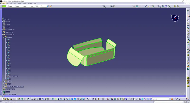
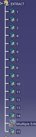
Fig. 8 & 9
STEP 2:
To create the below stracture we of to offset from the Class A Surface with the 2.5mm. The base is created are show below.
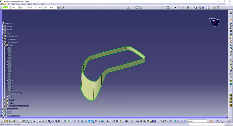
Fig. 10 & 11.
STEP 3:
Using "untrim tool" option untrim every extracted plane there are shown below.
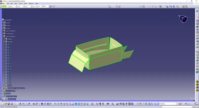

Fig. 12 & 13.
STEP 4:
Offset every surface with 2.5mm of it and the image is shown below.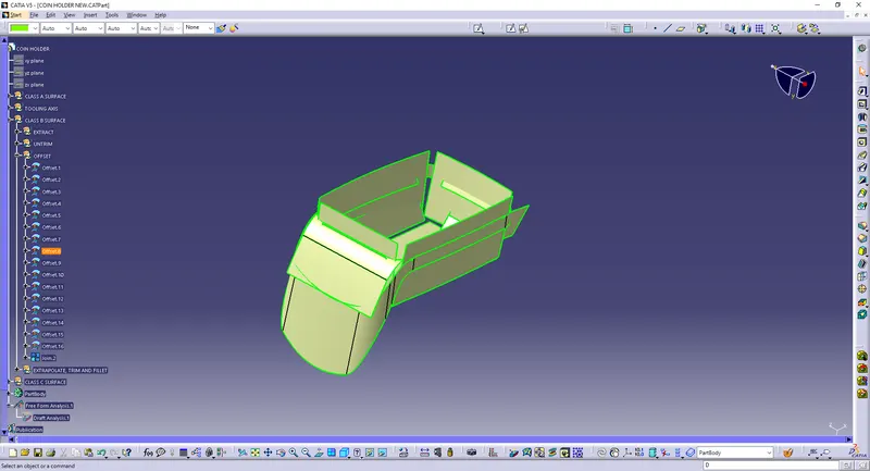
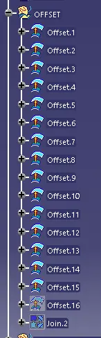
Fig. 14 & 15.
STEP 5:
After offset it we have to extrapolate each an every one of it are shown below.
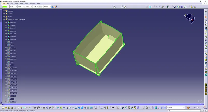
Fig. 16
STEP 6:
Trim tool is use to trim all the extra edges of the previous one of it are shown below.
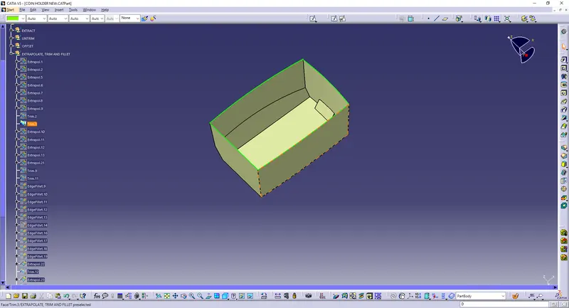
Fig. 17
STEP 7:
Extract the other plane or surface and trim it. Then previous one (in fig. 17) must joint with the fig. 18 is shown in fig. 19.
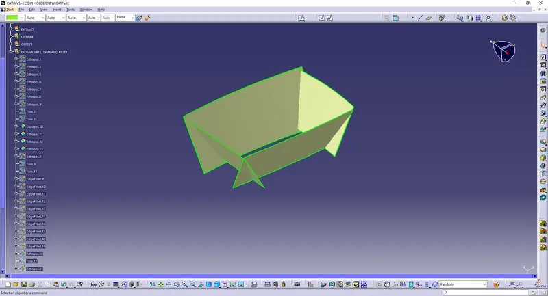
Fig. 18.
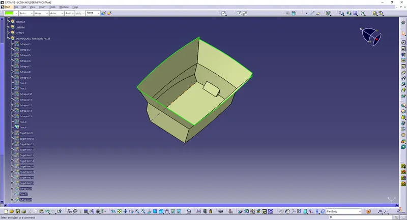
Fig. 19.
STEP 8:
After finishing the fig. 19 , the fillet tool is used for create radius for each of it and then the prodect has been created.
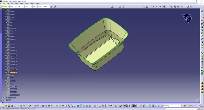
Fig. 20.
STEP 9:
Previously offseted part is used to joint with the fig. 20 are shown below.
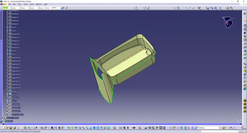

Fig. 21 & 22.
STEP 10:
Once again the fillet tool is used to create the Class B Surface are shown below.
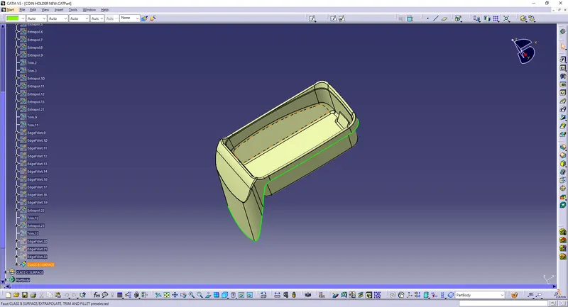
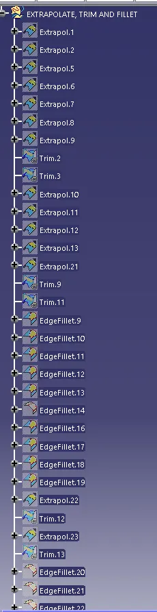
Fig. 23 & 24.
Class C Surface:
C surface has been created from the boundary lines of class A surface and by extracting the supporting surfaces then sweep the boundary lines with reference to the extracted surfaces.
In order to get the C surface first we have to create a boundary lines of class A surface or by using multiple extrapolated command and check for the continuity of it.
Create a sweep with reference to the curve and the reference surface with a 90 degree angle and give the inside direction Check for the continuity of the surfaces if there is any gap go for extrapolated and trim all together now we will get the class C surface.
Then join the class A surface and C surfaces together by join command then check it for connectivity of the surfaces if it is ok then finally trimmed it with B surface we will get the final component again check whether the final body is closed by using boundary command.
Closed solid body is created by using the close surface on part workbench by selecting the final Trimmed component and do the draft analysis for the same.
Class C Surface as shown as img. are given below:
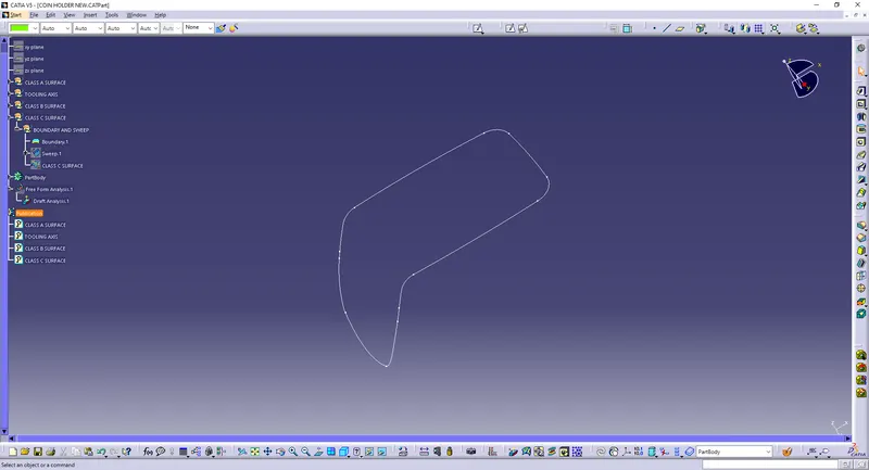
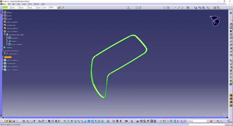
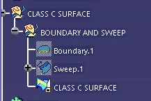
Fig. 25, 26 & 27.
CONCLUSION:
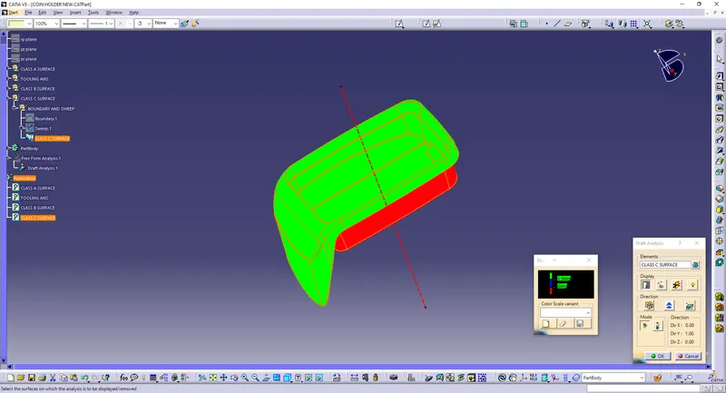
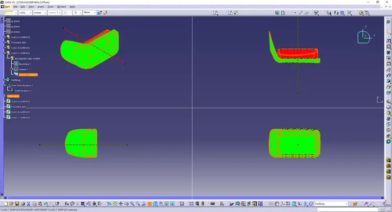
The drafting also take place over here wether the part is maufactureable are not are shown below.
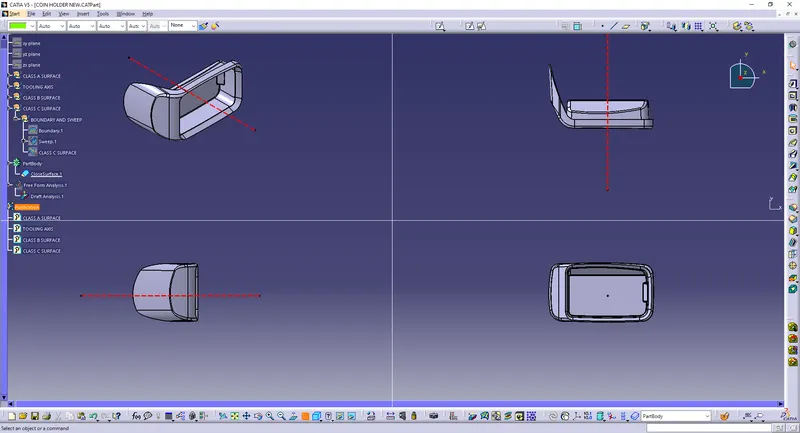
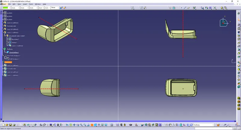
The part is coverted to soild also are shown below.
Finally the Class – A, B & C surfaces with the Tooling Direction have been Published and the Coin Holder Plastic is moved on to the designing of the next operation – the creation of B-side features.
Final product img. are given below:
Thermoset plastic:
Acrylonitrile butadiene styrene(ABS):
Acrylonitrile butadiene styrene (ABS) (chemical formula (C8H8)x·(C4H6)y·(C3H3N)z is a common thermoplastic polymer. Its glass transition temperature is approximately 105 °C (221 °F). ABS is amorphous and therefore has no true melting point.
ABS is a terpolymer made by polymerizing styrene and acrylonitrile in the presence of polybutadiene. The proportions can vary from 15% to 35% acrylonitrile, 5% to 30% butadiene and 40% to 60% styrene. The result is a long chain of polybutadiene crisscrossed with shorter chains of poly(styrene-co-acrylonitrile). The nitrile groups from neighboring chains, being polar, attract each other and bind the chains together, making ABS stronger than pure polystyrene. The acrylonitrile also contributes chemical resistance, fatigue resistance, hardness, and rigidity, while increasing the heat deflection temperature. The styrene gives the plastic a shiny, impervious surface, as well as hardness, rigidity, and improved processing ease. The polybutadiene, a rubbery substance, provides toughness and ductility at low temperatures, at the cost of heat resistance and rigidity.For the majority of applications, ABS can be used between −20 and 80 °C (−4 and 176 °F), as its mechanical properties vary with temperature.The properties are created by rubber toughening, where fine particles of elastomer are distributed throughout the rigid matrix.
ABS can be recycled, although it is not accepted by all recycling facilities.
ABS is one of many types of thermoplastic with biomedical applications, with injection-molded components being easy to manufacture for single-use. It can be sterilized by gamma radiation or ethylene oxide (EtO).
| Property | Value |
|---|---|
| Young's Modulus (GPa) | 2.28 |
| Tensile Strength (MPa) | 43 |
| Flexural modulus (GPa) | 2.48 |
| Flexural Strength (MPa) | 77 |
| Notched Izod (kJ/m) | 0.203 |
| Heat Deflection Temperature, 1.81 MPa, (C) | 81 |