Week 11 - Final project
Aim:
To Creation of CAD model considering Class A surface, Nominal thickness, Master Section and Attachment strategy.
Abstract:-
This report contains a brief theory on design rules and the approach followed to achieve the final plastic product. Draft analysis report on all the class-A surface apart from the procedure to make the class-B and class-C surface is also mentioned.
Introduction:
10 Stages of Product life cycle of automotive Industry are
1. Concept sketch
2. Styling class A
3. Feasibility check
4. Concept validation
5. New Product Design
6. Product Development
7. Proto Build
8. Design Validation
9. Pilot Production
10. Mass production
APPROACH:
Our basic approach to make a plastic model from class-A surface should be:
- Run draft analysis
- Make tooling axis
- Make B surface
- Make C surface
- Trim all together and make it solid.
Input Given:-
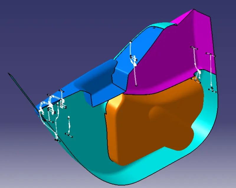
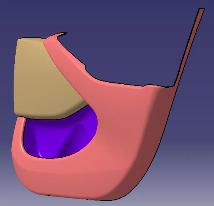
Interior Door trim consists of four components
1)Lower Substrate
2)Lower Map Pocket
3)Upper Map Pocket
4)Switch Bezel
THK - 2.5 mm ALLOVER
Draft analysis & Tooling analysis:
In the injection molding process, plastic products are difficult to demold due to friction force between the cavity and products, thus, finished products might be deformed or damaged. Therefore, designers should add a draft angle to the geometric surface of products, which is parallel to the unloading direction, in order to help the products eject smoothly from the cavity. This study uses CAD software as the main architecture to develop the function of automatic draft angle recognition and construction. The study is divided into three stages. First, the geometric features of products are identified in the CAD model by induced algorithm, then the quilts to be added in the draft design are determined and classified. Finally, draft angles are created in different ways according to different surfaces
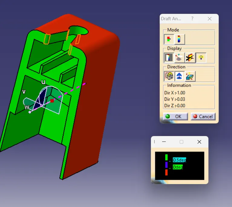
The draft analysis button within CATIA V5 will help you quickly gather the draft angle on multiple surfaces without the need for tedious manual measurements. Here is a quick rundown of how the icon works when you have a given die direction.
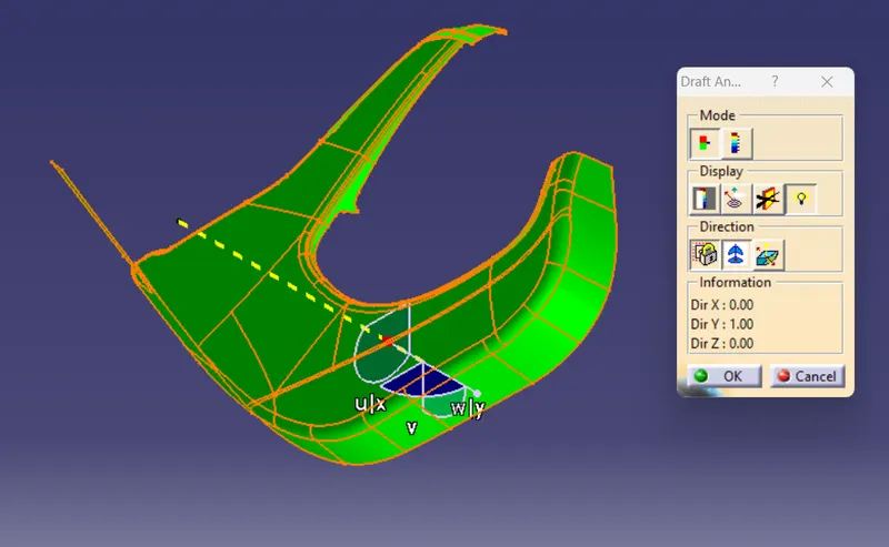
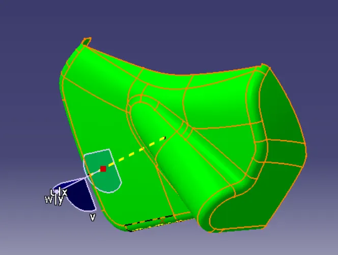
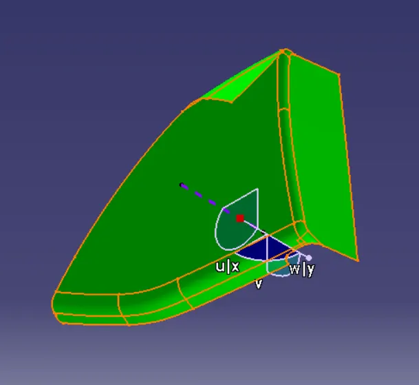
Draft Analysis Report on Class A Surface :-
1)Lower Substrate
2)Lower Map Pocket
3)Upper Map Pocket
4)Switch Bezel
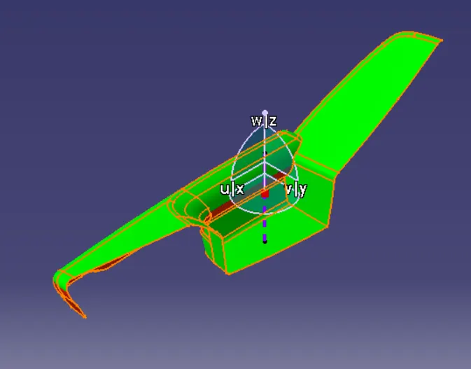
DESIGNING PLASTIC COMPONENT
As the entire door panel is divided into various components, we will make this plastic component in the same way. Following steps have been carried out to make the plastic component for every component:
The first step for every component was same. The given input was not a single unit but has numerous patches. These patches were joined together using join command. Thus after performing this operation we got our single class-A surface.
Once we get class-A, we have to proceed to make class-B surface. Creating class-B by extracting every flat surface will be a complex process in such component. So we directly offset it by 2.5mm.
For making class-C surface we have used sweep command ‘with draft direction’ by giving 3deg draft angle and tooling axis as direction. But at many places this did not work so we have to sweep ‘with reference surface’ at 90deg. Once that was done, the C surface was joined together using join command.
To make a final surface model, we have to trim all the three surfaces together. And later go to part design to close the surface.
Lower Substrate
Class-B surface was created by offseting class-A surface by 2.5mm distance And doing some rework on it. This is the nominal thickness of the component.
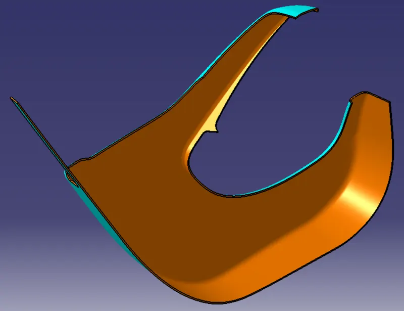
Class-C surface was created by sweeping it along tooling axis at some part and sweeping it with reference surface at other. In the end every patch was joined together to get class-C surface.
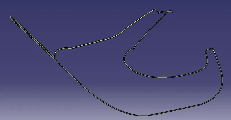
Final surface model was created by joining class-A and class-C surfaces together and later trimming them with class-B surface.
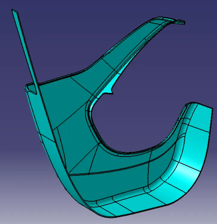
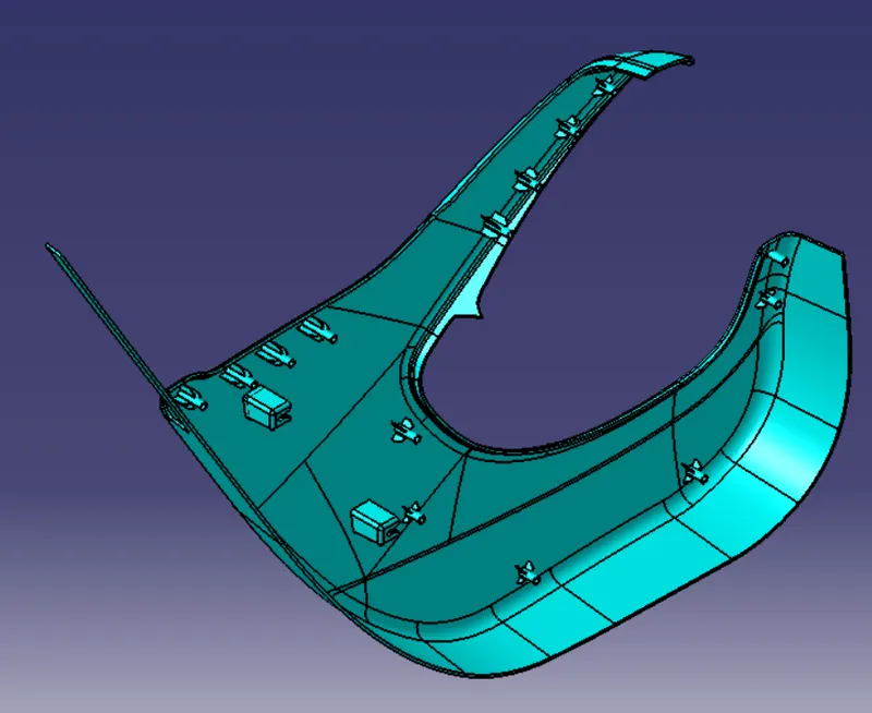
Model after creation of all engineering featues
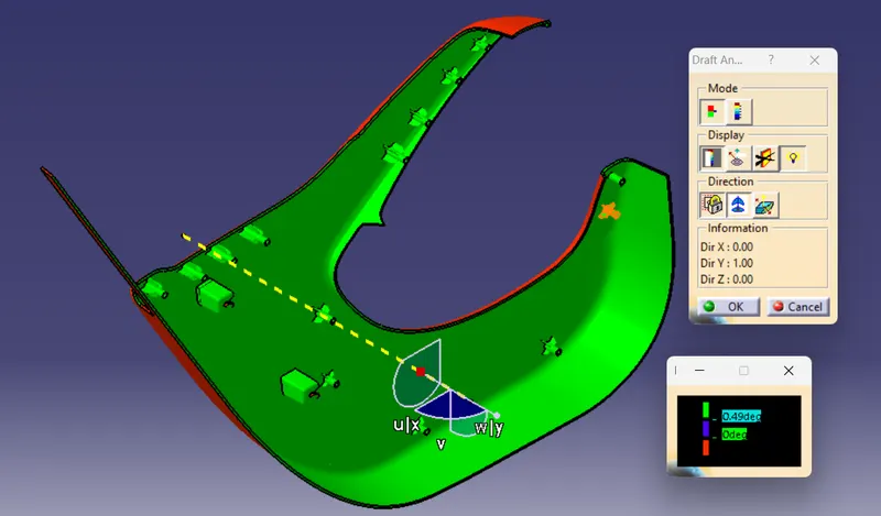
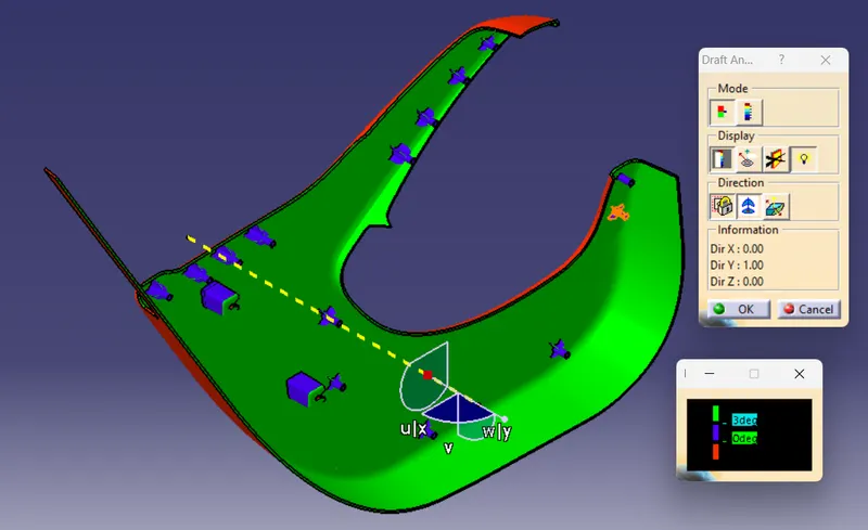
Draft Analysis:-
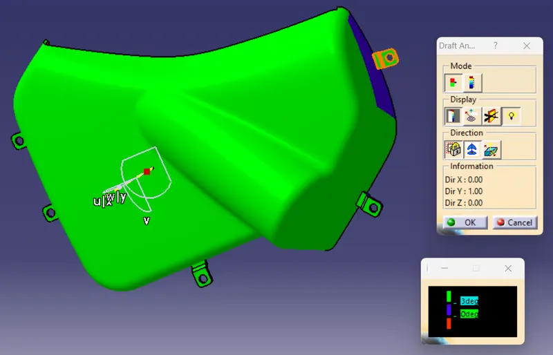
Engineering features is created with draft angle of minimum 0.5 deg.
Nominal Draft angle is 3 deg for all faces.
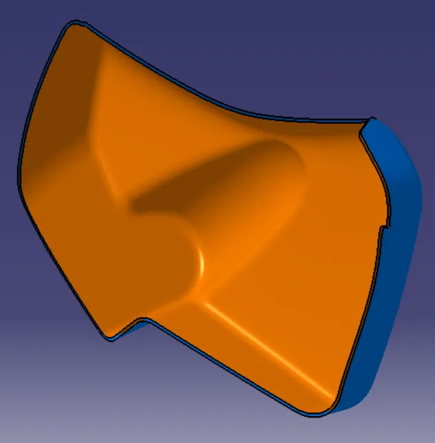
2)Lower Map Pocket
Class B Creation
C Surface Creation
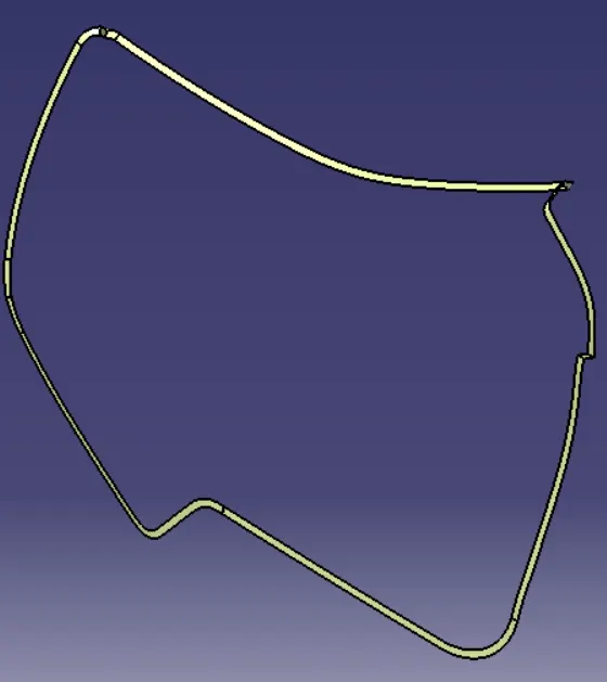
Final Model
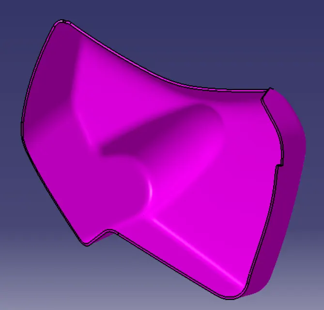
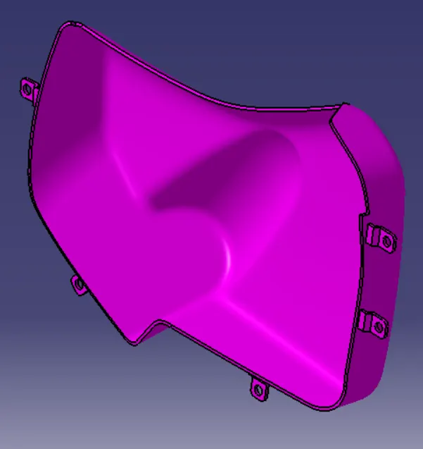
Draft Analysis
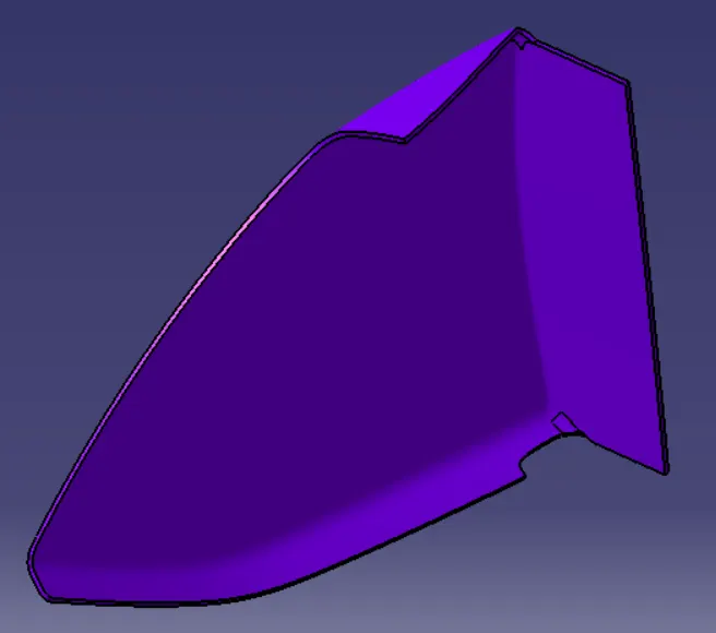
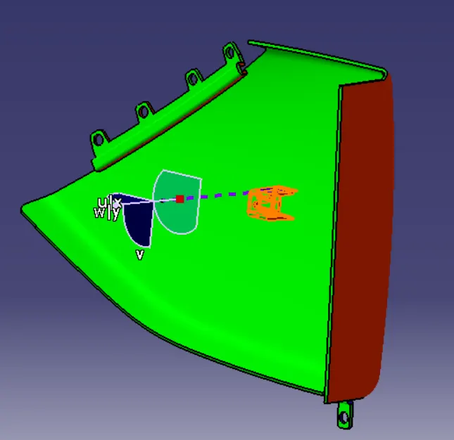
3)Upper Map Pocket
Class B Creation
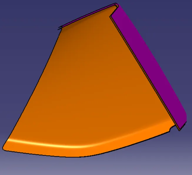
C surface Creation
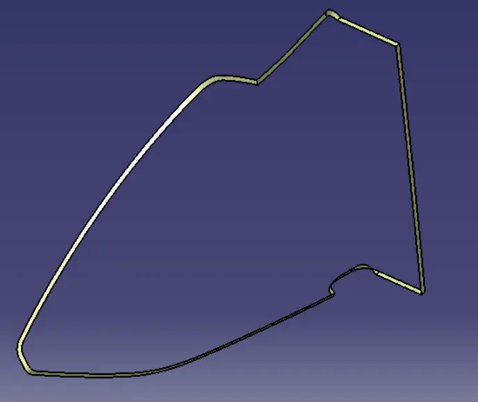
Final Model
Attached Enginnering Features with draft analysis
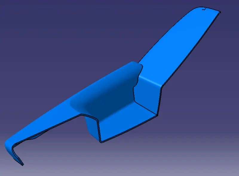
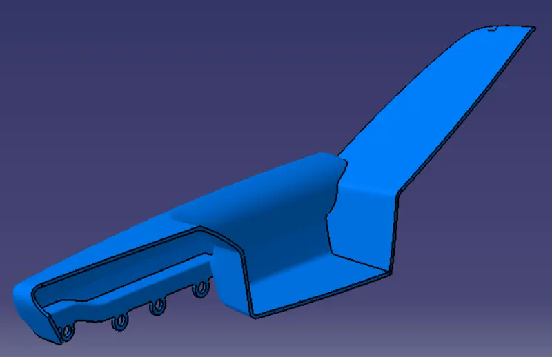
4)Switch Bezel
Class B Creation
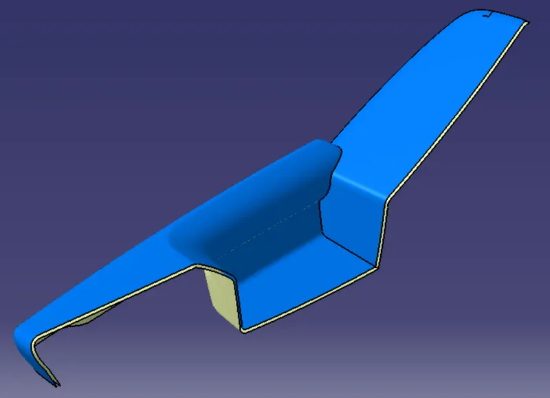
C Surface Creation
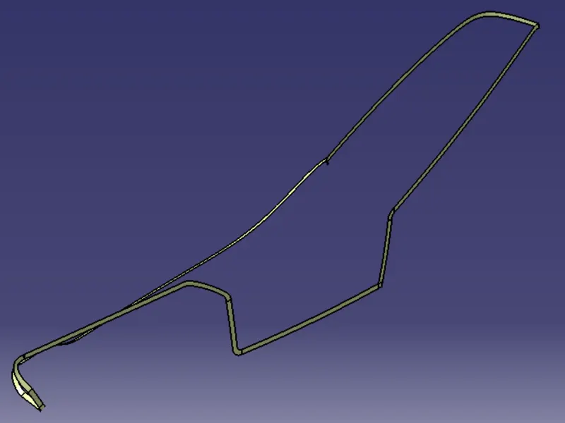
Final Model
With Engineering Features
Engineering Features Design Guidlines -
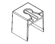
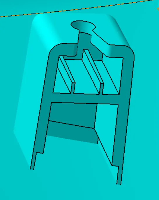
DOG HOUSE: Primary function of the dog house is to avoid sink marks. But it also helps in other things like if the mating part is to be at a greater distance then we cannot make the height of the screw boss of that greater height, thus we make dog house and mount screw boss on it. Hence it helps in solving the problem of screw boss and also it helps to have perpendicular screw boss.
GENERAL DESIGN GUIDELINES FOR DOG HOUSE DESIGN:
- Minimum height: Less than 6mm causes steel condition.
- 3:1 ratio of steel width to height. But 2:1 is preferred.
- Minimum width: 3:1 ratio of steel width to height. But 2:1 is preferred.
- Draft: minimum 1.5deg.
- Sink saver: Width= 40% of nominal thickness. Height= 3.0mm-6.0mm
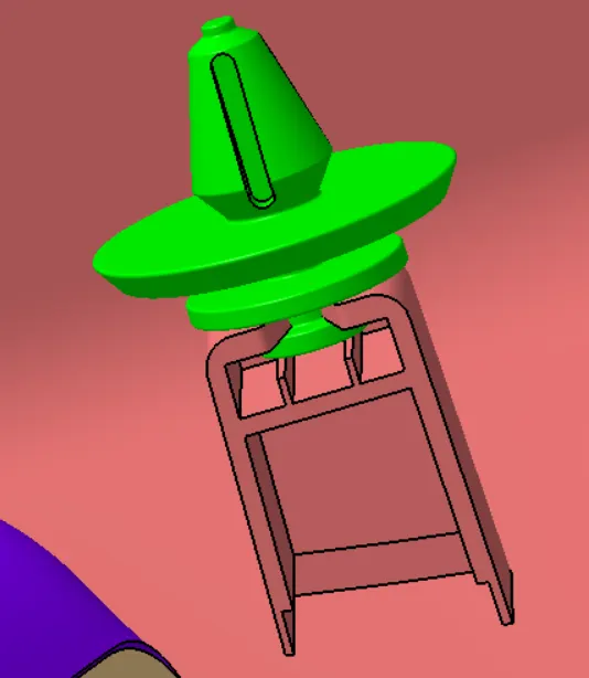
With main tooling Axis-
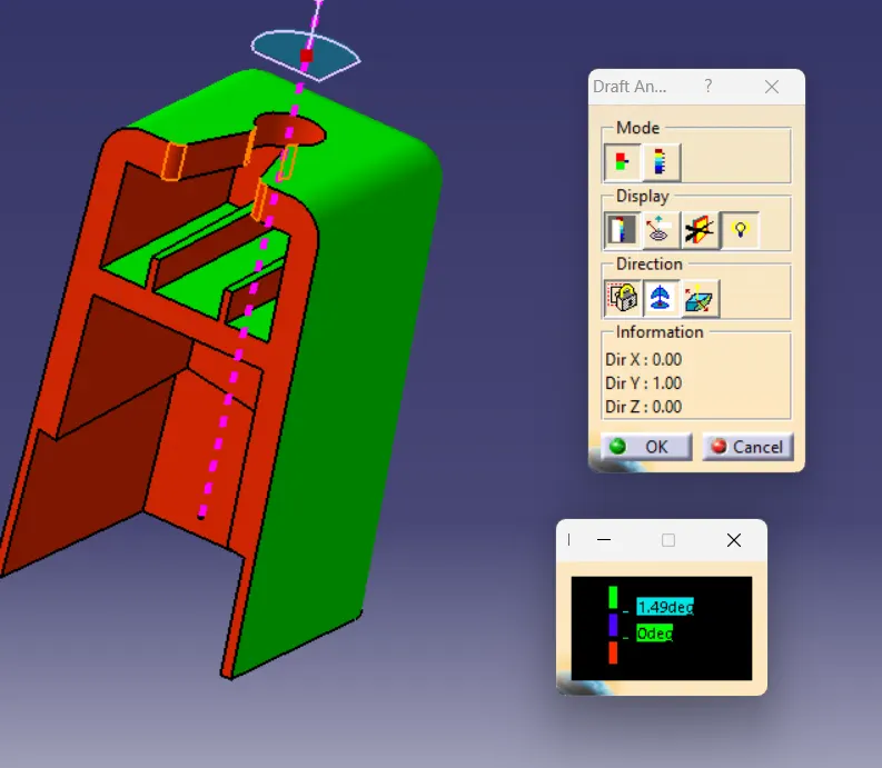
With Side Core Tooilng Axis
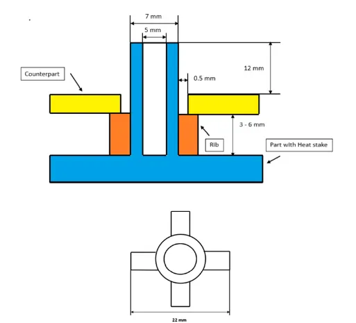
Heat Stake
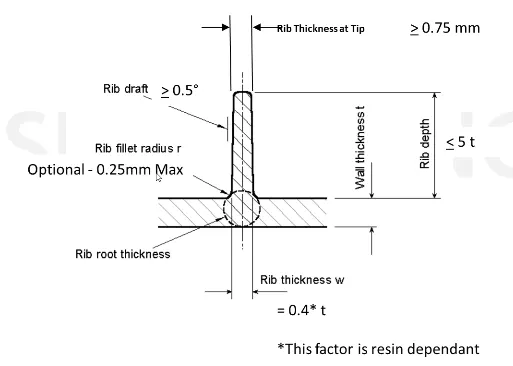
Rib Design
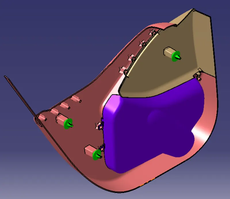
Assembly Model Picture-
Heat Staking Benefits:
- Similar and dissimilar materials may be joined: metal to metal, plastic to plastic, metal to plastic
- Accurate control operating within a small process window
- Local heating resulting in no damage to surrounding materials
- Processing of glass-filled materials
- No mechanical vibration
- Many heat-stake shapes are possible through custom designed tools.
Materials best suited for Heat staking:
Heat staking technology is ideal for most native and blended thermoplastics on the market today, as well as the most robust glass and/or other-filled plastics. It produces high quality results when used with any of the following materials:
- Polycarbonate (PC)
- Polypropylene (PP)
- Polystyrene (PS)
- Acrylonitrile butadiene styrene (ABS)
- Nylons (GFN or Nylon 6/6)
- Ultem (GFN or Nylon6/6)
CONCLUSION:
Hence, Input surface is extracted into different components and B-side Features are created considering the OEM standards to design Plastic components.