Photo Realistic Rendering
Designing & Assembly
Of
American Chopper
This Report
Is Created & Submited
By
Pavan Ghumare
Under Guidence
By
SKILL LYNC
OBJECTIVE:
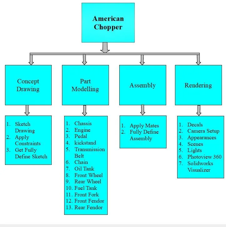
The objective of this project is -
° To make indivisual parts of the model with proper constraints & fully define status.
° Learn the tools & features of solidworks Software.
° To assemble all the parts by fully define mates.
° Know the application of Decals, Lights, Appearences & Cameras.
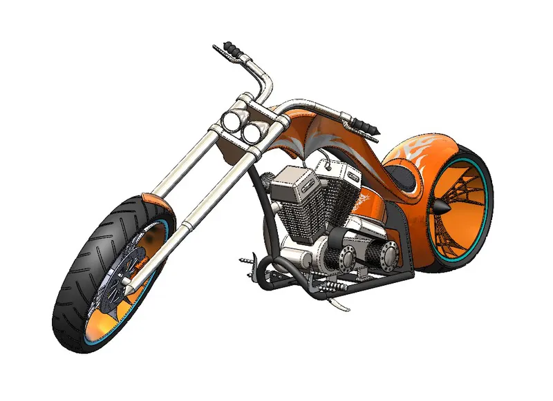
° To create photo realastic rendering of model by using Photo View 360 & Solidworks Visualizer.
INTRODUCTION:
Solidworks was developed by Dassault Systems. Hirschtick's original team developed and released SolidWorks software by the end of 1995.
It is 3D Modeling software which uses concept based sketches to create model and very handy user interface which allow us to move tabs by our convinient. It has many featues like when we edit any part file it get automatically updated in model, assembly & drawings.A part can become a component in an assembly, and it can be represented in 2D as a drawing.
It has option like we can look how was the weight of the object by puttting density or appliying materials. It is very easy to make 2D drawing (Top view, Front view, Side view or Isometric view) from 3D model.
The Feature Manager tree allow us to see which fetures we used in model and to make changes in that in very less time. It has an add-ins...option to anable featues like photo view 360 which helps in rendering of model. we can generate High Quality images of model looks like orignal by applying Lights, Scenes, Cameras & appearences.
It has some Extension for that files-
1. Drawing - .slddrw or .drw
2. Part - .sldprt or .prt
3. Assembly - .sldasm or .asm
Design Methodology/ Approach :
Terminologies :
This Commands are applicable for all models of solidworks.
Plane - There are three palnes by default (Front, Top, Right). Planes Can be used for 2D sketch, to View section views of a model.
Axis - Axis are used for referance or to give dimensions while sketching. Its a straight Line
Face - A face is a selectable area (planar or non-planar) of a model or surface.
Edge - It is Line where two or more faces intersect with each other.
Vertex - Point where two or more lines or edges intersect.
Sketch - Use to Draw the 2D sketch to apply constraints
Features - Use to convert 2D sketch to 3D model or to apply various feature such as extruded cut, fillets. Decision to apply appropriate feature is very important while modeling the part.
Assembly - This feature uses diffrent approach. It is used to combine diffrent part file to make whole assembly by applying mates to fully define it.
Sketch Tools:
Smart Dimension - Automaticaly detect which type of Constraints we needs After moving the cursor.
Line - A line is a one-dimensional figure, which has length but no width. A line is made of a set of points which is extended in opposite directions infinitely. It is determined by two points in a two-dimensional plane.
Circle - The circle is another important tool which use to create the circular drawing on the graphics area. Types of circle tools are Center circle and Perimeter circle.
Spline - A two dimensional curve defined by the set of control points. Shape of the spline is define by the weight of the Handles.
Rectangle - There are five rectangle tools available while sketching we can use by our convnience.
1) Corner Rectangle
2) Centre Rectangle
3) 3 point corner rectangle
4) 3 point centre rectangle
5) Parallelogram
Arc - It is the incomplete circle. Types of arc listed below,
1) Centre point arc
2) Tangent arc
3) 3 point arc
Ellipse - Ellips having two radius values or two axis.
Text - It allows to insert text in the sketch.
Straight Slot - This feature allows to make a slot having ends are closed by arcs
Polygon - It’s having multiple edges. Can be used to create multi edge sketch between 2 to 40 edges.
Sketch Fillet - Fillet describe rounded corners of design. It allows to apply corner radius at intersection of two lines.
Chamfer - By applying this tool the sharp edge gets remove. Chamfer are sloped or angle adges usually between 45 to 60 degree.
Point - It is a 1 dimensional entity. Insertion of point into a sketch entity by clicking where the point we want .This can not be deleted if it is part of sketch end point or center point.
Trim Entities - Extended lines or sketches can be remove by applying this feature
Extend Entities - It is used to extend the lines upto the next line or a point which allow us to enlarge the same line.
Convert Entities - Convert Entities enables to copy edges ,lines into your active Plane. This sketch elements are automatically fully defined and constrained with relation.
Offset Entities - This tool use to copy a sketch entity to a specified distance from the original entity. It must having the sketch entity already drawn and selected to use this feature.
Sketch Picture - Insert an image into background of athe sketch. This allows to draw 2D sketches based on the image. Use the sketch picture property manager to alter the inserted image.
Mirror Entities - Create a mirror copy of the sketch entity about a center line or axis.
Linear Sketch Pattern - Linear sketch pattern can be use to make multiple entity of same dimensions on Linear line.
Circular Sketch Pattern - Circular sketch pattern can be use to make multiple entity of same dimensions on circular way.
Move or Copy Entities - Dimensions are moved or copied to the new location with the entities. Relations are moved or copied only if we select Keep relations.
FEATURE COMMANDS :
The Features given by solidworks has most importance because they are very accesible while creating a 3D model. By applying feature we can work directly on 3D model.
Some listed features are given below-
Extruded Boss/Base - An Extruded Boss/Base feature will allow to make 2D sketch into 3D sketch by adding thickness to it as a third dimension.
Revolve Boss/Base - This feature allows to make 2D sketch to the circular 3D model by revolving to the center line or axis. It allows to control the angle of revolve body that we need upto 360 degree.
Swept Boss/Base - It sweeps a close profile along with open or close path to create a solid feature.
Swept Cut - It is totally reverse of swept boss/base. In this we remove the material by selecting path.
Lofted Boss/Base - Add material between two or more profiles to create a solid feature.
Lofted Cut - This is totally reverse of lofted cut. It removes material between two or more profiles to cut the solid feature.
Extruded Cut - It cuts a solid model by extruding the sketch profile in one or two directions.
Revolve Cut - It cuts a solidmodel by revolving a sketch profile around the axis. we can select which bodies to keep and which one to remove by selecting it.
Fillet - Fillet describe rounded external or internal face along one or more edges on solid or surface feature. fillets having more option to apply on edge based on requirement.
Chamfer - Chamfer describe sloped external or internal face along one or more edges on solid or surface feature. Chamfer having more option to apply on edge based on requirement.
Linear Pattern - It is a tool to copy the original tab a specified number of times. The linear pattern creates multiple instances of a selected feature along a linear path.
Circular Patterns - Circular Patterns create copies, or instances, in a circular pattern controlled by a center of rotation, an angle and the number of copies. The instances are dependent on the originals. Changes in the originals are passed on to the instanced features.
Curve Driven Pattern - The Curve Driven Pattern tool allows to create patterns along with a specified path or 3D curve. To define the pattern, we can use any sketch segment, or the edge of a face (solid or surface), that lies along the plane.
Sketch Driven Pattern - The sketch driven pattern creates copies of existing features and places them wherever we've added a point in a sketch. It's that simple. All it takes is a sketch created specifically to place instances of a feature.
Shell - The shell feature hollows out the part, leaves open the faces we select, and creates a thin-walled features on the remaining faces. If we do not select any face on the model, we can shell a solid part, creating a closed, hollow model. We can also shell a model using multiple thicknesses.
Edit Feature - Edit Feature provides a simple method to change the information used to create a feature. To edit any feature, right-click the feature either in the Feature Manager tree or the model, and select Edit Feature.
Section View - Generally section view are use when we Can’t give dimentions to hidden lines. For that we need one more cut view i.e. section view There are many types of section views.
Mirror - Features can be mirror about a plane or planar face. The mirrored features maintain a relationship with the original features such that any changes to the original features are also made on the mirrored features.
Split - To seperate one body into multibodies the split tool is used. By selecting trim tool we are able to cut the bodies into two seperate bodies. Consume cut bodies option allows to keep the cut body or not.
Combine - This is reverse of split tool. In a multibody part, we can combine multiple bodies to create a single body. We can combine only bodies contained within a part file. We can not combine two separate parts.
Dome - It can creates one or more domes to the selected faces. The software calculates the distance using the radius of the arc as a basis for the dome.
Pierce Relationships - Sketch relationships are relationships between different types of sketch entities. Pierce relations can be added to sketch points and an axis, edge, line or spline. They are especially useful for ensuring that a coincident relationship is formed between entities of varying axis. A pierce relationship is required to ensure that two entities from different axis collide or cross paths .the center point of entities can be selected to move the sketch entity to a mutual position.
Reference Geometry - As name suggest the Reference geometry defines to use that foe reference purpose. Reference geometry includes items such as planes, axes, coordinate systems, and points. We can use reference geometry in the many features in a different ways.
Project Curve - Select Bi-directional to create a projection that extends on both sides of the sketch. The curve can be used as a path for a sweep.
Composite Curve - We can create composite curves by combining curves, sketch geometry, and model edges into a single curve. Composite curve can be used as a guide curve when creating a loft or a sweep.
Split Line - The Split Line tool is used to project an entity (sketch, solid, surface, face, plane, or surface spline) onto other surfaces or curved/planar faces. We are also able to split faces on multiple bodies with one command.
Assembly Exploded Views - Exploded views is use to exlpode the hole assembly to see how is the assembly mates together and also to view the hidden parts available in that assembly.
Degrees of Freedom - There are six degrees of freedom for any component that is added to the assembly before it is mated or fixed. Translation along the X, Y, and Z axes and rotation around those same axes. How a component is able to move in the assembly is determined by its degrees of freedom. The Fix and Insert Mate options are used to remove degrees of freedom.
Features used in parts :
· Projected Curve
· Composite Curve
· Swept Boss/Base
· Curve Driven Pattern
· Cicular Pattern
· Linear Pattern
· Extrude Boss/Base
· Extruded Cut
· Revolve Cut
· Swept Cut
· Lofted Cut
· Chamfer
· Fillet
· Dome
· Combine
· Split
· Mirror
· Shell
·
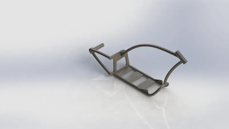
Chassis -
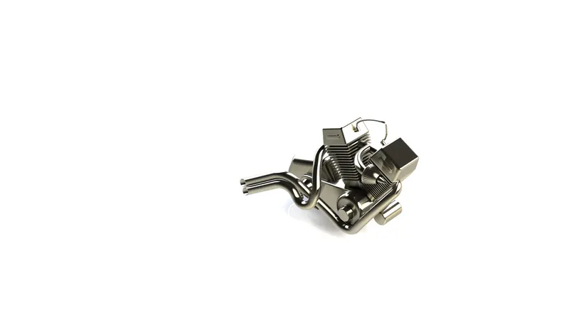
Engine -
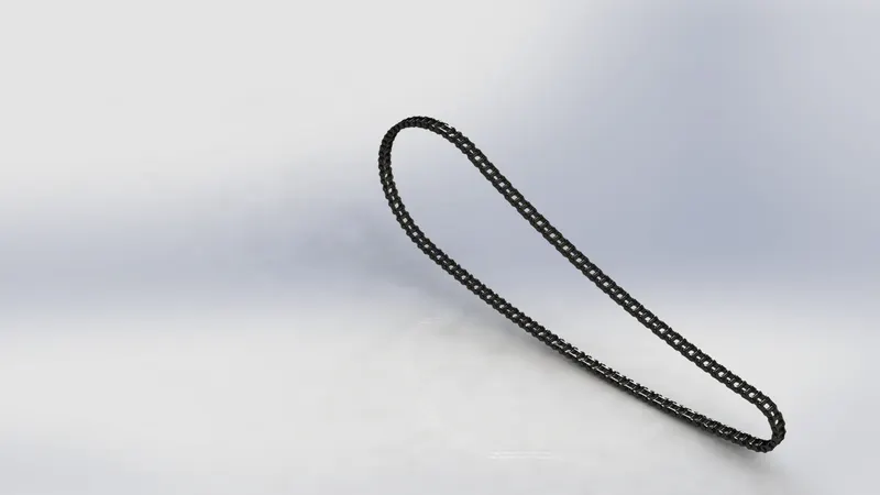
Chain -
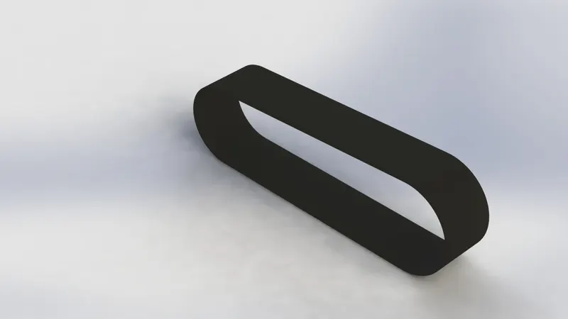
Transmission Belt -
Kick Stand-
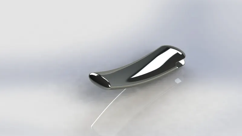
Front Fendor-
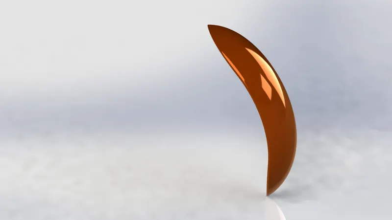
Rear Fender -
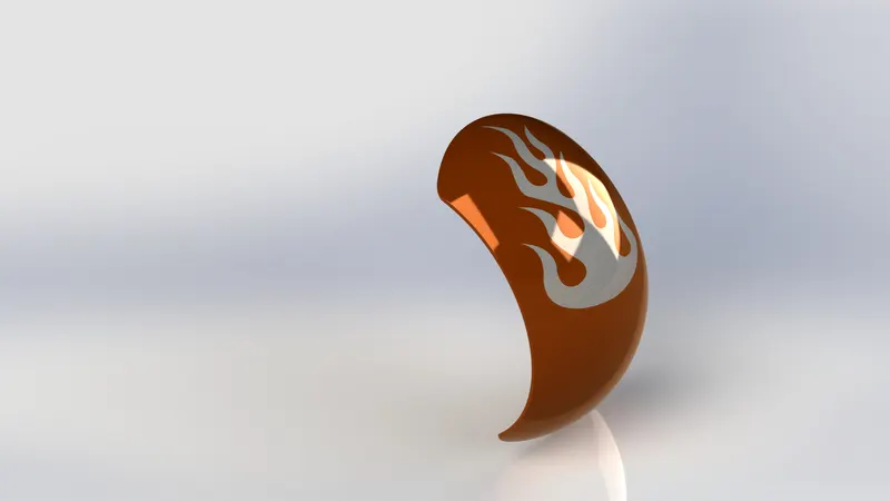
Pedal -
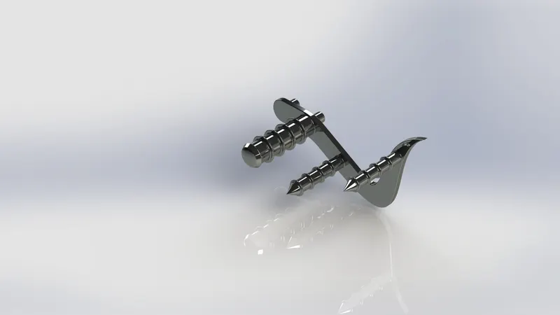
Oil Tank-
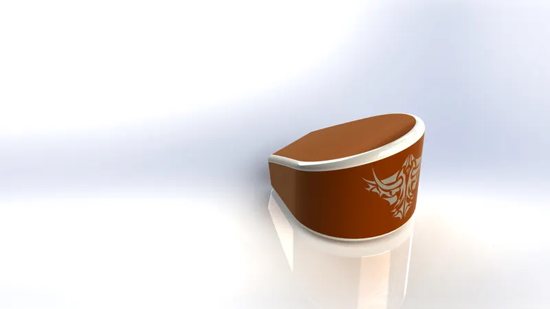
Fuel Tank-
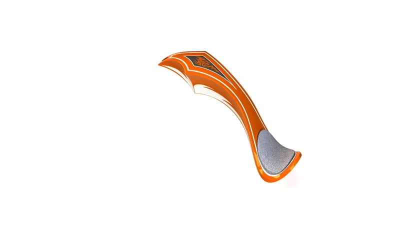
Front Wheel-
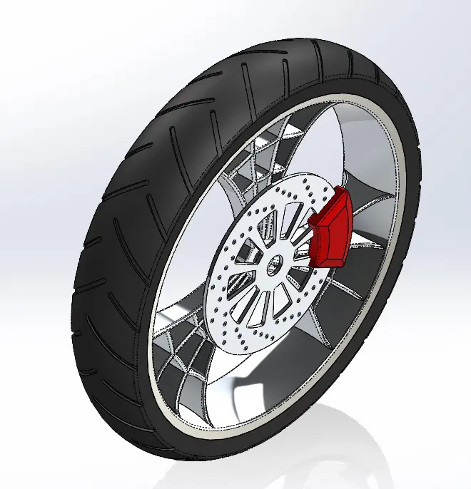
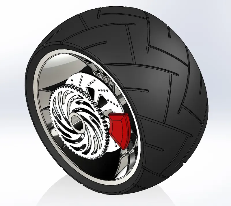
Rear Wheel-
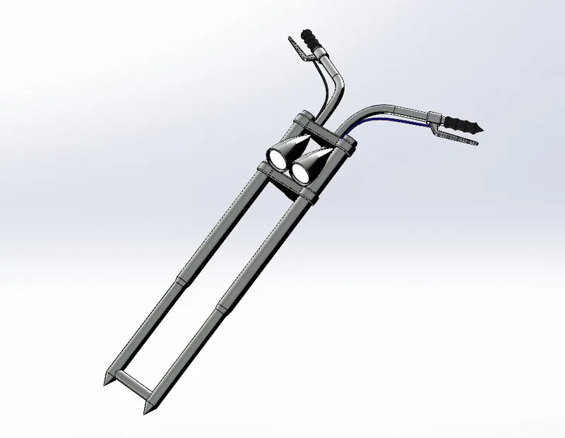
Front Fork-
Features used in parts :
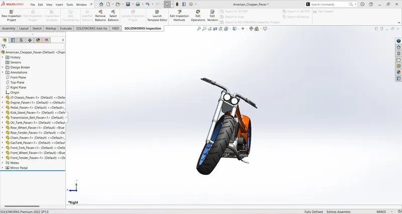
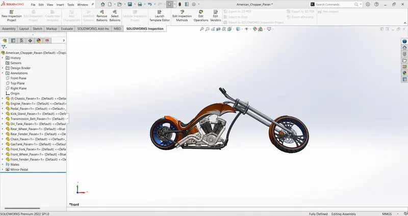
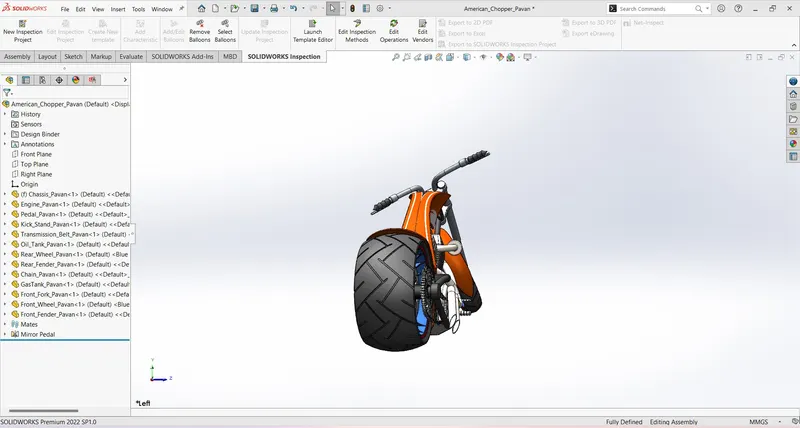
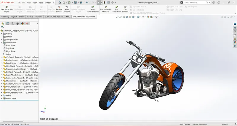
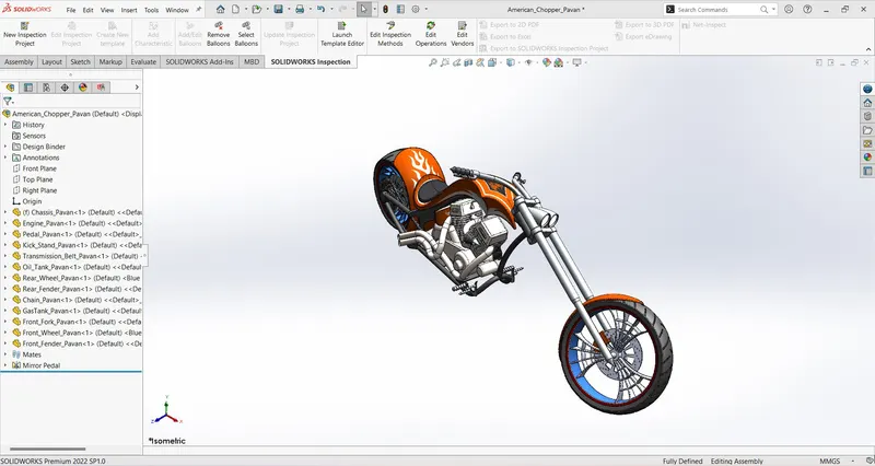
After modelling all parts the next step is to assemble them by proper Mates. The part models in assembly of solidworks is define by relation with each other. While creating assembly in solidworks we are locking their Degrees of freedom to get fully define assembly.
Mates -
Mates defining the relation of components with each other. positioning the parts define how they are move or rotates with each other.
Mates having some relations -
coincident, Concetricity, parallel, etc.
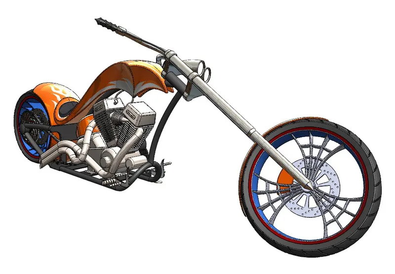
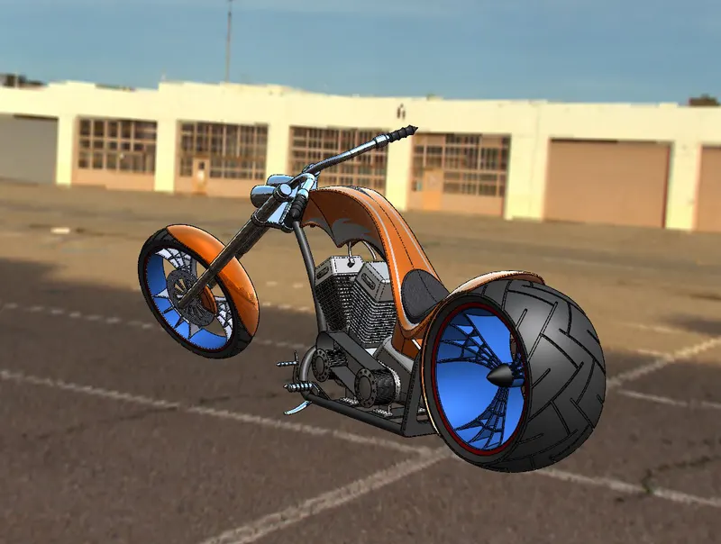
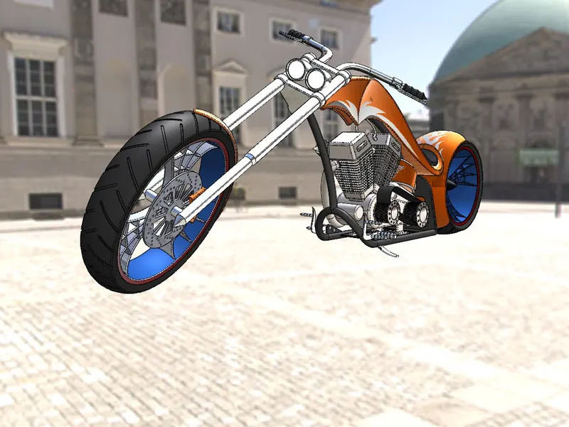
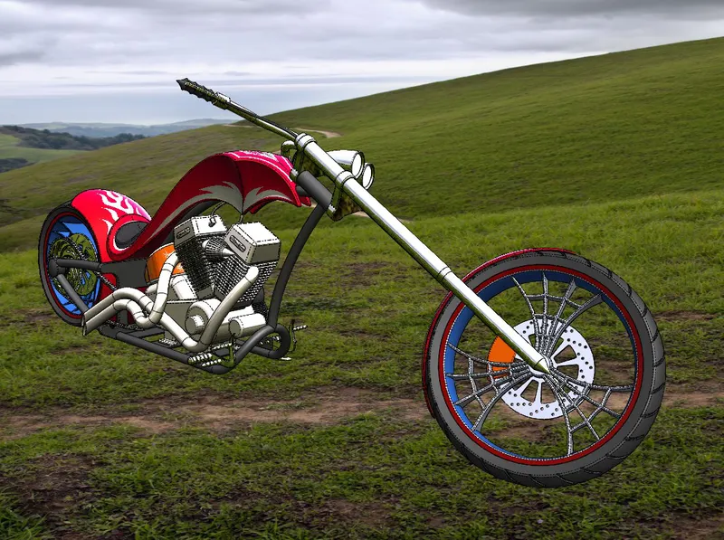
Conclusion :
Thus in this way the project of Design and Assembly of American Chopper Bike with photo realistic rendering using SOLIDWORKS has been created and completed successfully.