Week 11 - Final project
DOOR TRIM PANEL DESIGN
To create solid plastic parts of door trim panel and to add engineering feature to it like haet stakes, ribs, flange and Dog house with given Class A surfaces and multisection.
Parts in Door trim panel
1.Lower substrate
2.Bottle holder
3.Map pocket
4.arm rest
1. LOWER SUBSTRATE
Lower substrate is larger component in dooe trim panel. Here I am going to create Class B surface and Class C surface with given class A surface and convert into to solid part and add engineering features.
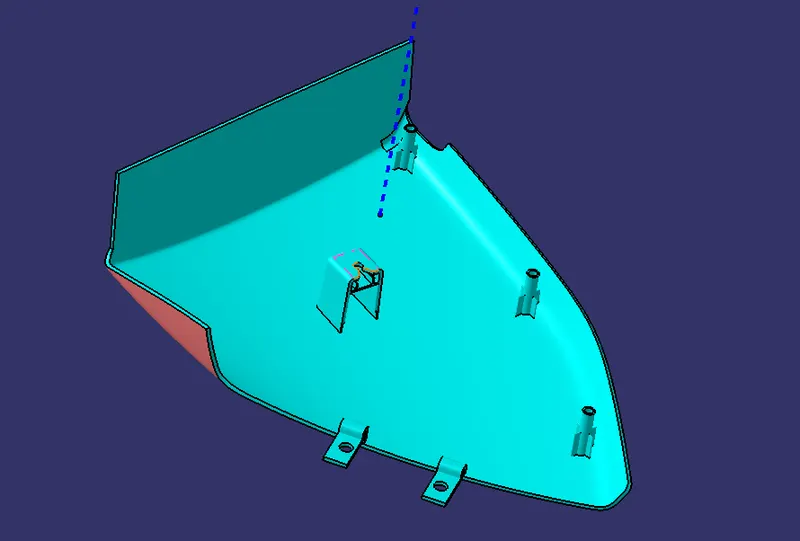
1. To check quality of the Given Class A surface draft analysis have to be made for that tooling axis have to created in the proper direction. In this case I have created the tooling axis with point to direction method and draft analysis made on it.
In draft analysis most of the surface are in green which means all surface with minimum draft.
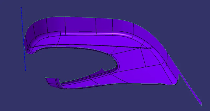
Tooling Axis and Class A surface
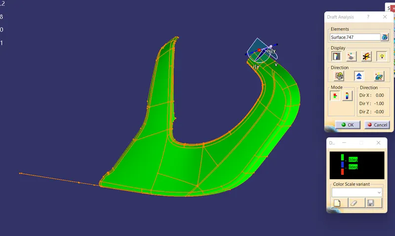
Draft analysis on Class A surface
2. Class B Surface was created by offset the class A surface to 2.5 mm inside. Offseted surface was checked through out to see is there is any gap. Boundaries of class B surface extrapolated and some areas tonexten the class B surface sweep options are used.
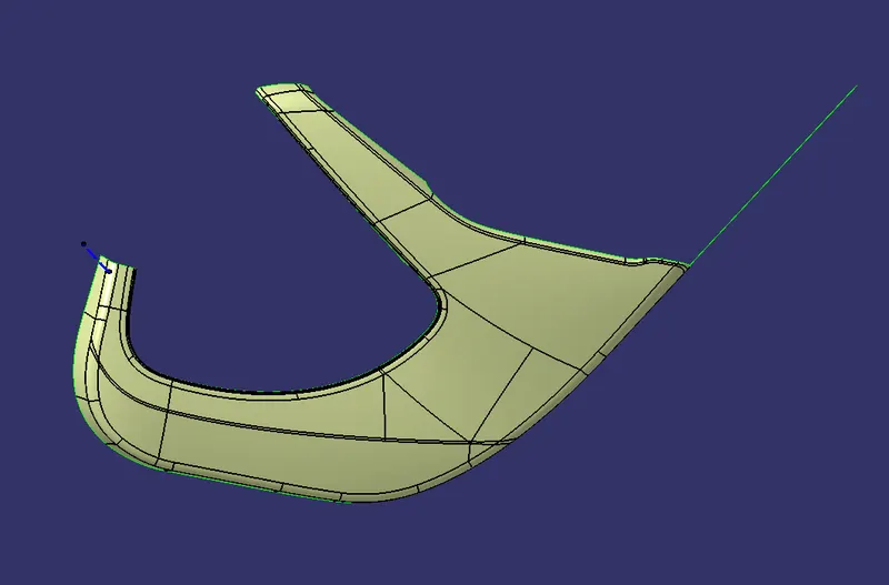
Class B Surface
3. Class C surface was created using Sweep command with reference to surface at 90 degree where ever the surfaces are perpendicular to tooling axis and with draft direction at 3 degree where ever the surfaces are parallel to tooling axis. Some area of C surface created using multisection.
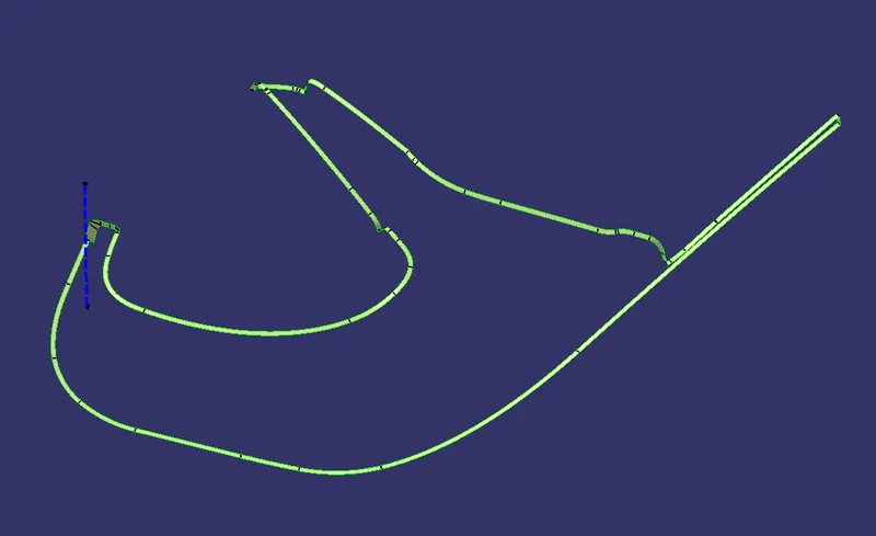
Class C Surface
4. To get final output from surface workbenck class a surface and Class C surface are joined. Join of class A and Class B are trimed with Class B. later quality of the surface using boundary command.
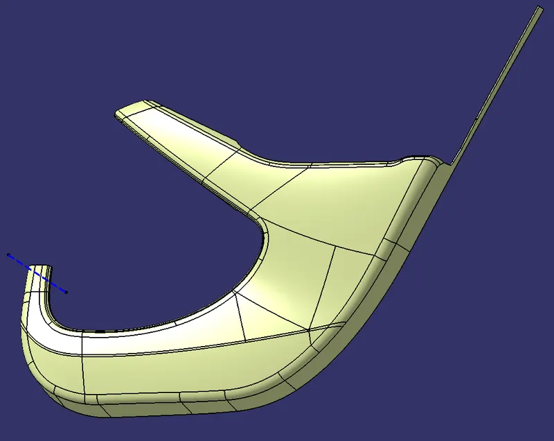
Join of Class A B & C surfaces
5. Final output from surface workbench converts to solid in part workbench using close surface command and draft analysis made on it most of Class A Surface are in green color means with minimun draft 3 degree and C surface which parallel to tooling is with minimun draft of 0.4 degree.
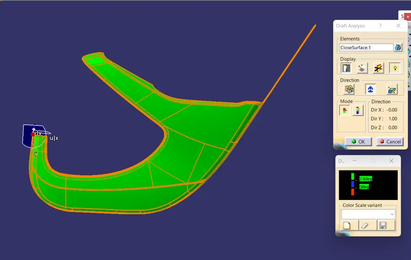
Draft analysis on solis component
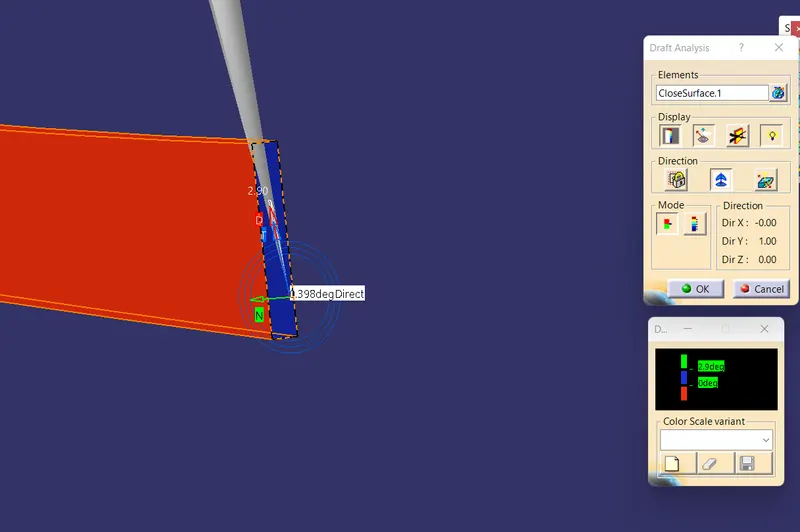
In C surface this area only not cleared with 3 degree draft but have 0.4 degree draft
6. Engineering features like Dog house, Heat stakes are created and draft anlysis made on it.Here I have created 11 haet stakes with with ribs , 2 Dog house and Flange.
Outer surface of dog house are with minimum draft of 1.5 degree and Inner surface with minimun draft of 0.5 degree. Heat stakes and ribs are with minimun draft of 0.5 degree.
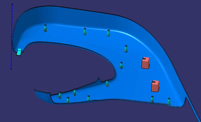
Overall Component with all engineering features
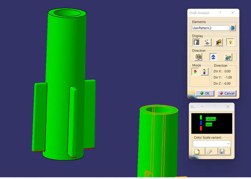
Draft Analysis made on heat stakes and ribs
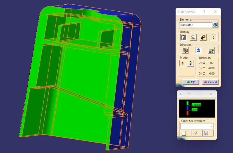
Draft Analysis Inside of Dog house
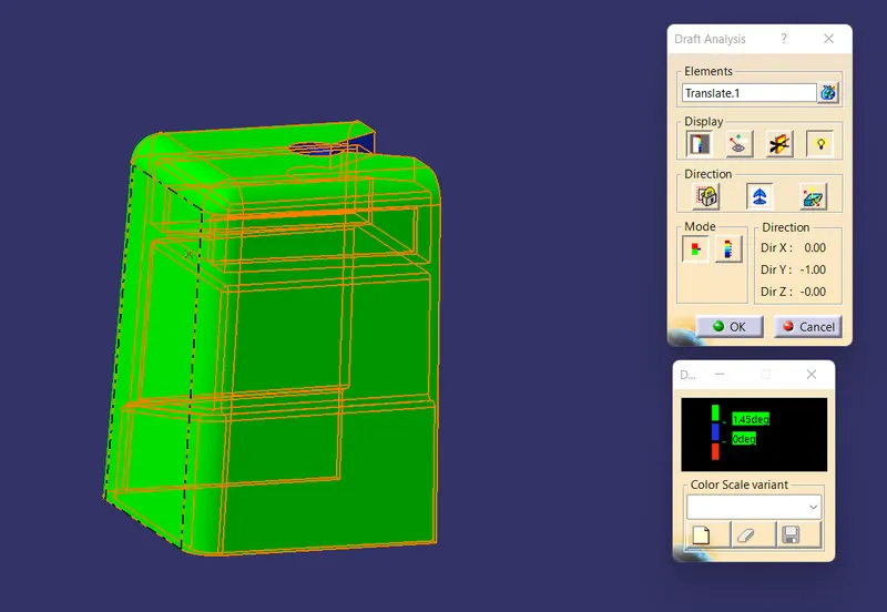
Draft Analysis Outside of Dog house
2. BOTTLE HOLDE
Bottle holder is also a large component in Door trim panel. Here I am going to create class B surface and class C surface with given class A surface and Converts it into solid part and add engineering features.
1. Draft analysis have to be made on class A surface and to check the quality of the A surface for that tooling axis have to be created. To created tooling axis I have used to methods Normal to surface method and point to direction method. Comparing draft analysis with the two tooling axis. Draft analysis with point to direction method is better than Normal to surface method.
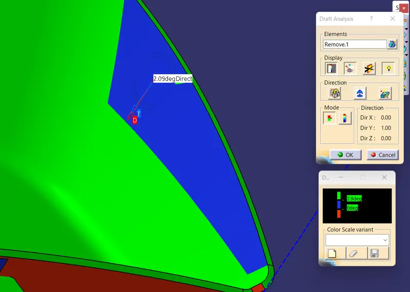
In draft analysis Some of the side wall surface are in blue color Some of the surfaces are with minimun 2 degree and some of it with 0 degree.
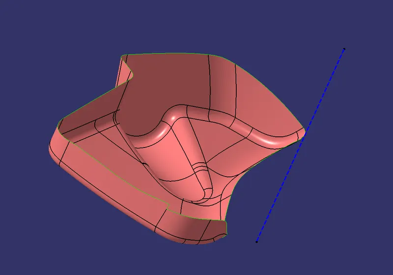
Class A surface with Tooling Axis
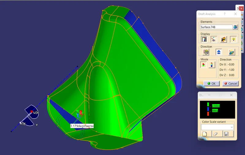
Draft Analysis
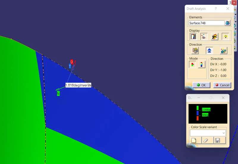
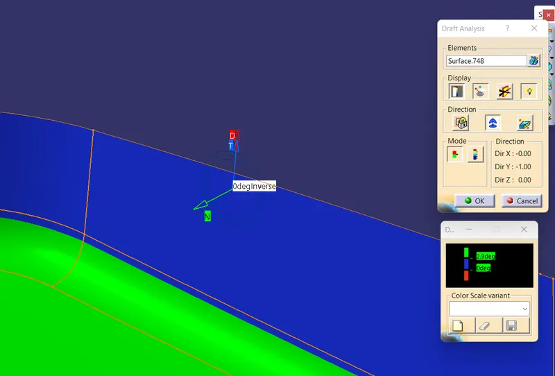
2. Class B surface are created by offsetting the class A surface to 2.5mm in inner direction in this offset all surfaces are come properly so no modification made on offset it was directly taken as Class B surface.
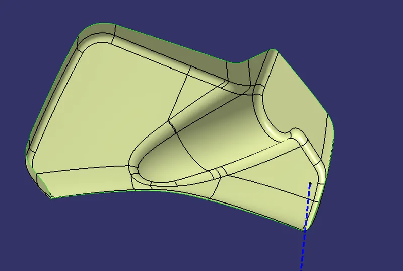
Class B surface
3. Class C surface are created using Sweep command with reference surface at 90 degree because all are surfaces are perpendicular to the tooling axis.
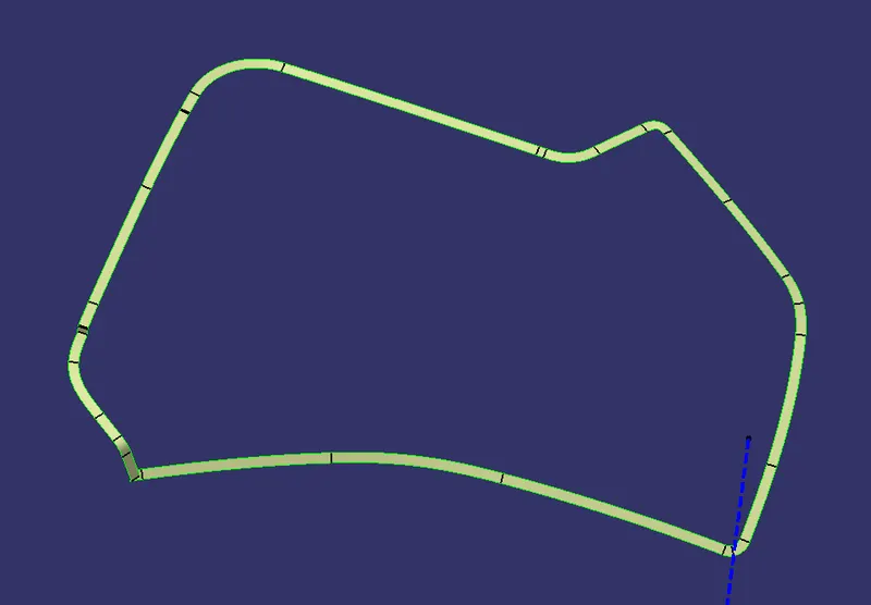
Class C Surface
4. To get final output from Surface workbench Class A surface and Class C surface are joined. Join of Class A nad C are trimed with Class B surface.
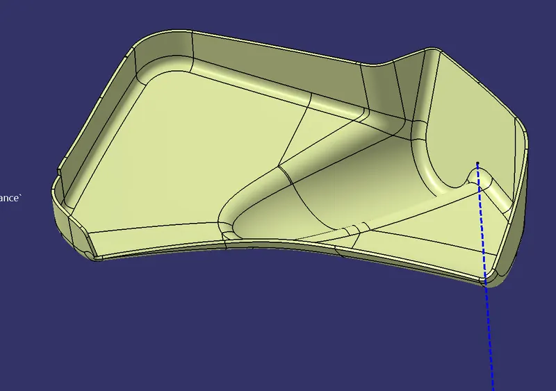
Join of Class A B & C
5. Fianl output from surface workbench converts to solid part in part workbench using closesurface command and Draft analysis made on final plastic component. Due to No draft surface in Class A surface it was reflected in Final part also.
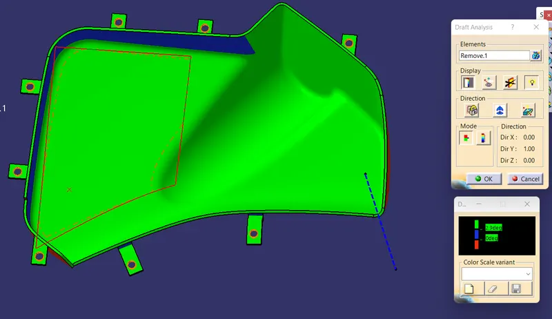 4
4
Drfat analysis on final part
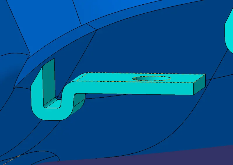
6. Engineering features like flanges are added to Join with other door trim panel parts. Totally 8 flanges are attached.
3. MAP POCKET
Map pocket is created with Given Class A surface. Class B and Class C surface are created with given class A surface and converts to solid part. Engineering features line Flange, Heat stakes and Dog house are attached to it.
1.To check the quality of the given class A surface, Draft analysis have to be made on A surface. For that tooling axis have to be created , here I have created tooling axis with point to direction method. In draft analysis most of the surface are in green color means with minimun draft of 3 degree.
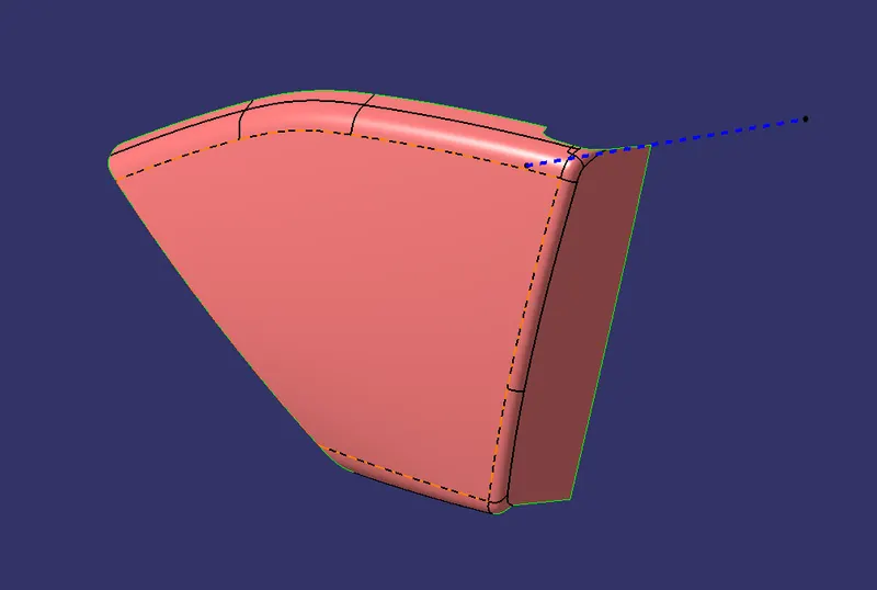
Class A surface with Tooling Axis
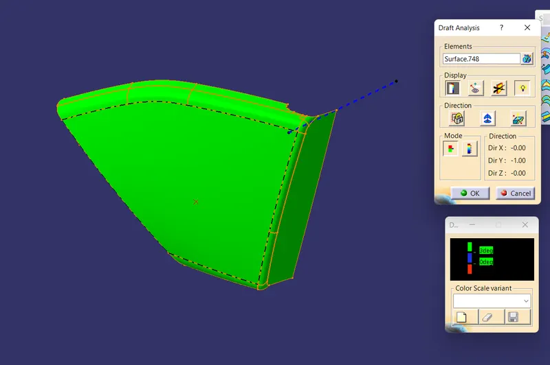
Draft Analysis on Class A surface
2. Class B surface are created by offseting Class A surface to 2.5mm in inside direction. In the offset some of the surface are missed. Missed areas areas are filled with multisection and all boundaries of class B Extrapolated to few mm.
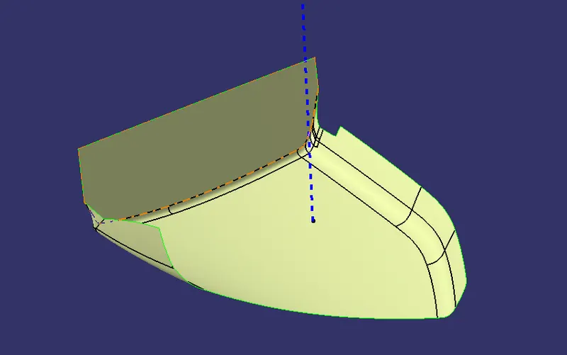
Class B Surface
3. Class C surface are created by using Sweep command with reference to surface command were ever surfaces are perpendicular to tooling axis and with draft direction were ever surfaces are parallel to tooling axis.
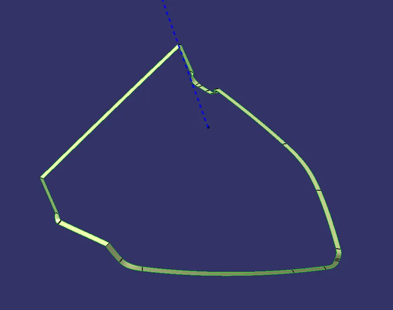
Class C surface
4. To get final output from surface workbench Class A and C surfaces are joined together. Join of class A and B are trimed with Class B surface.
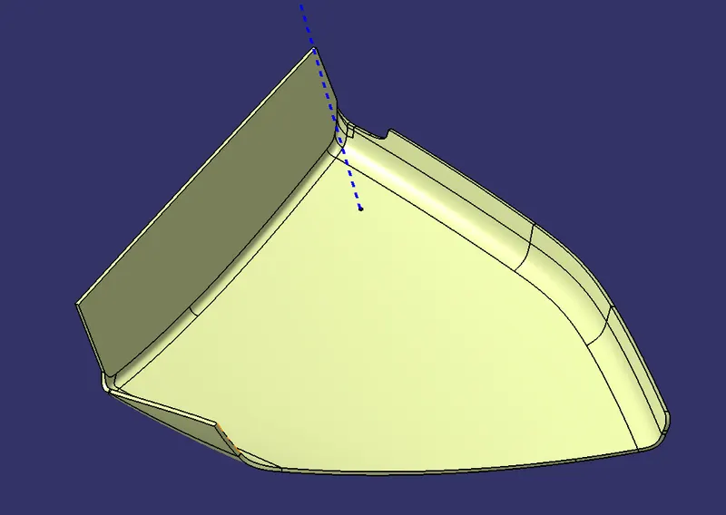
Join of Class A B & C
5. Final output from surface workbench converts to solid body in part workbench using close surface command and draft analysis made on plastic component all the class A surface are in green color means with 3 degree draft.
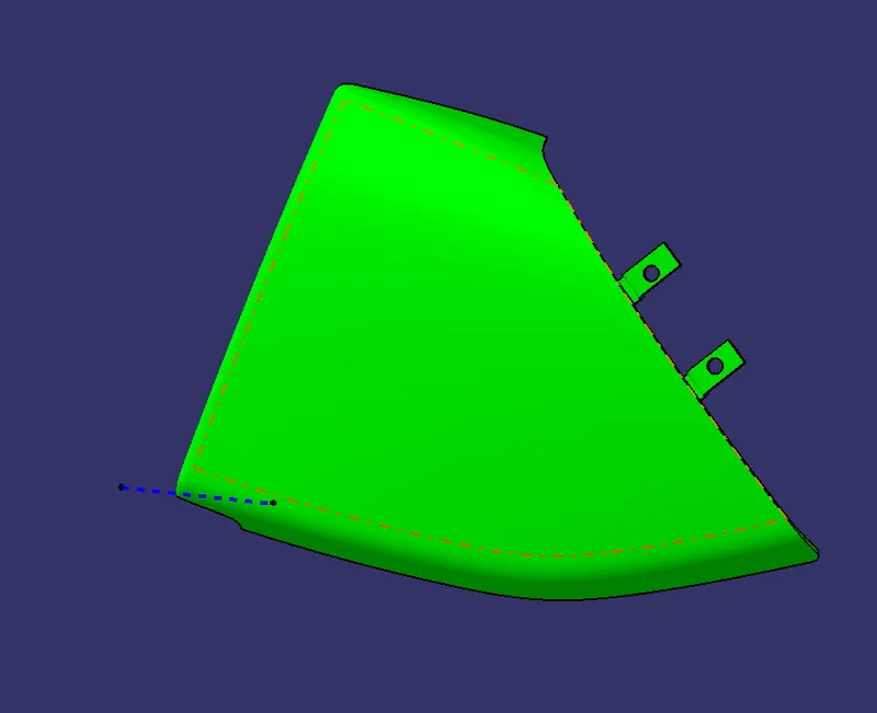
Draft analysis on final part
6. Engineering features like Flanges, heat stakes and Dog house are attached to it. 2 Flanges, 3 Heatstakes and 1 Dog house are attached. Draft analysis made on dog house and heat stakes.
Outer surface of dog house are 1.5 degree draft with main tooling axis and inner surfaces are 0.5 degree draft with side tooling axis.
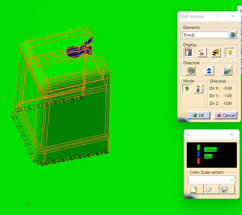
Draft analysis on outer surface of dog house
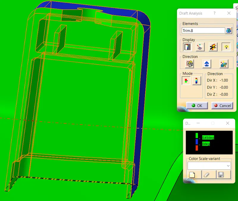
Draft analysis on inner surface of Dog house with side tooling axis
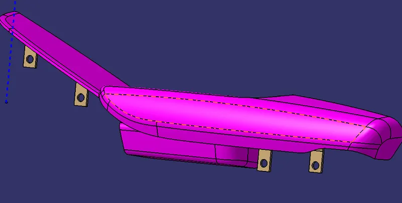
4. ARM REST
Arm rest are created using given class A surface. Class B And C surface are created with given Class A surface and converts to solid body in part workbench and engineering features like flanges are add to it.
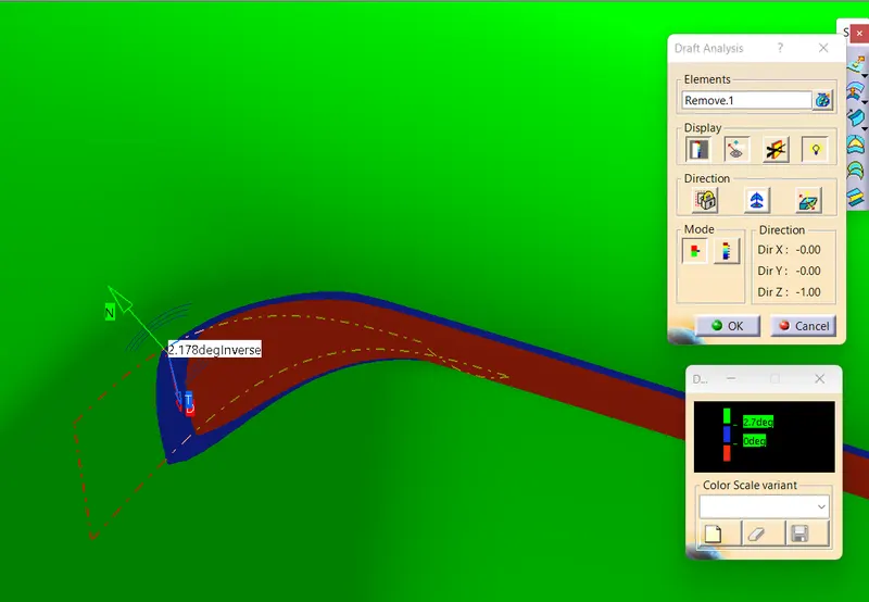
1. To check Quality of the guven class A surface draft analysis have to be made on it for that tooling axis have to be created. Here I have created the tooling axis with point to directin method. In draft analysis most of the surfaces are in green color and some of the surface in red color.
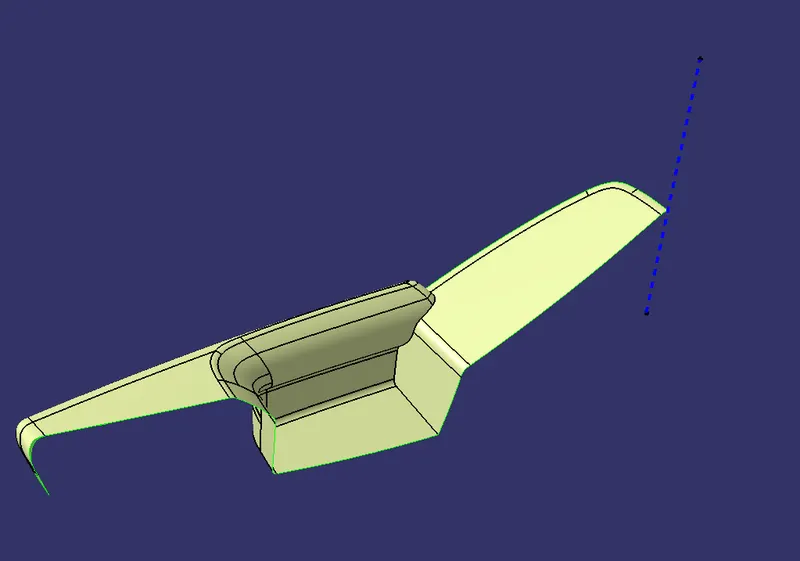
Class A Surface and Tooling Axis
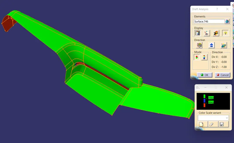
Draft Analysis
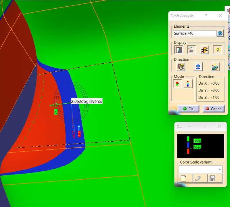
There is one gap in class A Surface which was cleared using Extrapolation and Extarcted method. Unwanted projections from class A surface was removed from it.
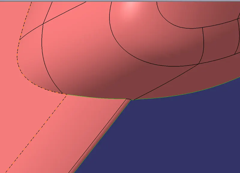
Given Class A Surface Before Improvement
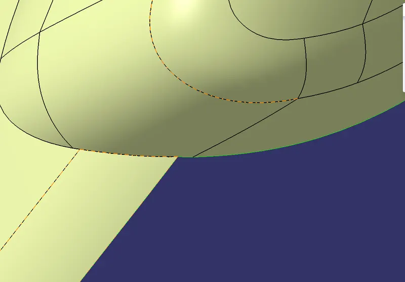
After Improvement
2.Class B surface are created by offseting the Class A surface to 2.5mm in Outer direction. In that offset some of the surfaces are missing it was filled with multisection. Surfaces of class A Surface are extrapolated to few mm.
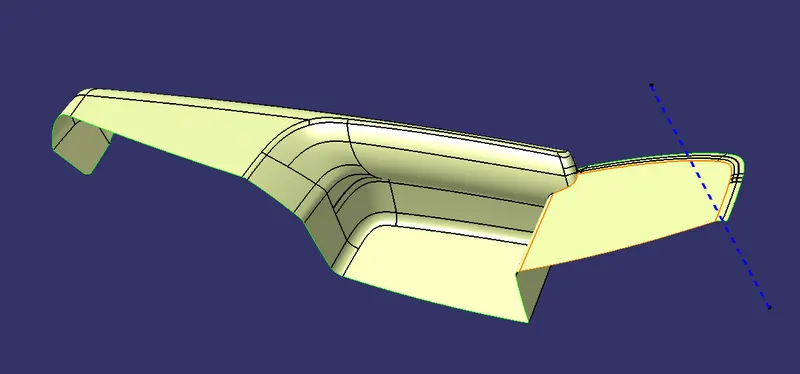
Class B Surface
3. Class C Surface are created using Sweep command with reference to surface were ever surfaces are perpendicular to tooling axis and with draft direction were ever suirfaces are parallel to toolin axis.
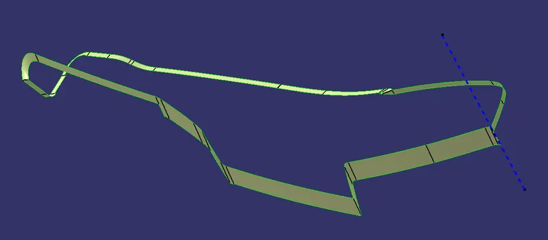
Class C Surface
4. To get final output from surface workbench Class A nad Class C surface are joined together and Join of class A nad c rae trimed with Class B.
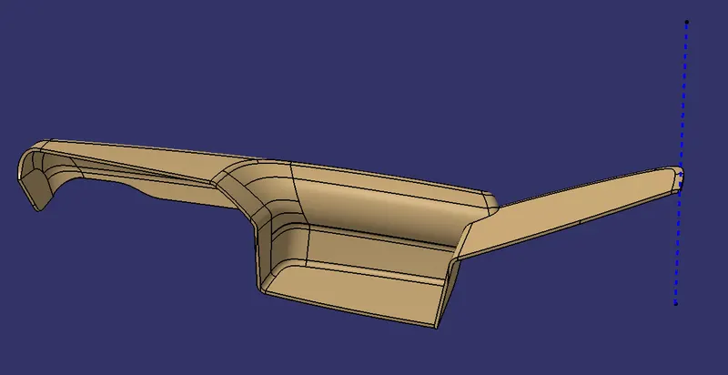
Join of Class A B & C
5. Fianl output from surface workbench converts to solid part in part workbench using closesurface command and draft analysis made on it all the class A surface with minimun draft of 3 degree.
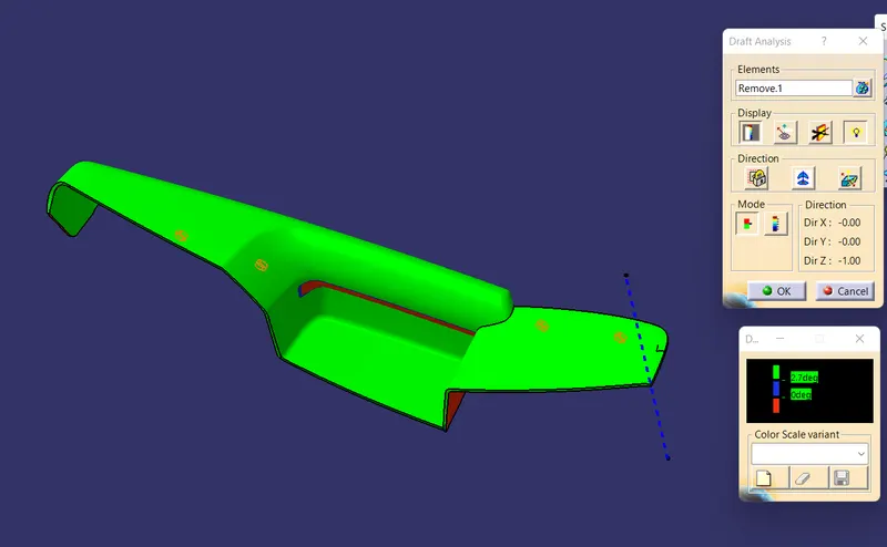
Draft Analysis on Solid part
6. Engineering Features like Flanges are attached to it. Totally 4 Flanges are attached to it.