Week 11 - Final project
Aim :
To create a CAD model of a side door trim panel from given class A surface.
Objective:
- a) Creation of side door trim panel from given class A surface . Apply thickness to it and use attachment features.
- b) Creation of flanges and heat stakes from given master sections.
- c) Creation of dog house and various attachment features using industry standards
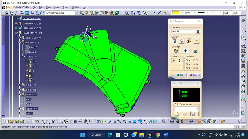
- d) Performing draft analysis and ensuring the features and surfaces clear it.
Introduction :
The ten stages in automotive product life cycle development are listed below.
1)Concept sketch
2) Styling class, A
3)Feasibility check
4)Concept validation
5)New product design
6)Product development
7) Prototyping
8)Design validation
9)Pilot production
10)Mass production
From the above stages, it is in stage 5 that new product is developed and validated from class A surface. The objective is to design class B and class C surface from given class A surface and create a solid body from it using software’s like CATIA V5, solid works or solid edge taking into consideration the draft analysis which makes the component suitable for production using injection molding process.
Given below is the procedure to create a new plastic component from given class A surface .
1) Creation of tooling axis
2) Creation of class b surface
3) Creation of class C surface
4) Creation of closed body
5) Draft Analysis .
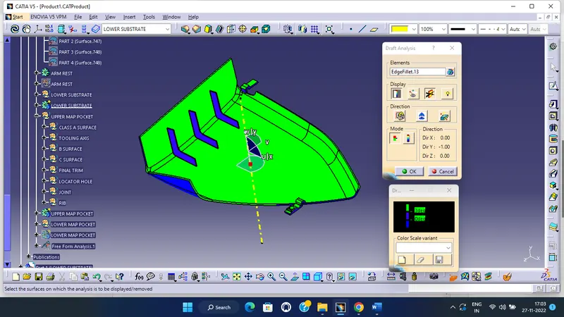
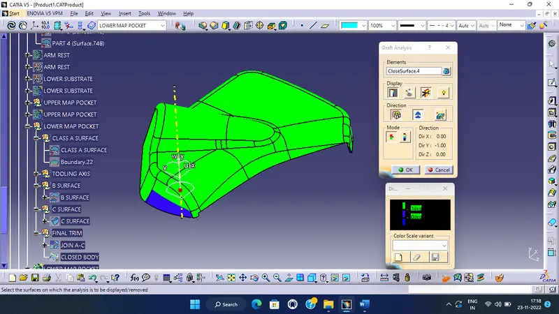
Draft analysis is done to ensure that the designed part is manufacturable based on the draft conditions applied. It is done to ensure the proper ejection of the component from dies(for metals) or molds(for plastics). The basic idea is to ensure that the tooling axis has to be created in such a wat that it has no parallel surface profiles of the component so that the ejection of the components can be ensured. Tooling axis is the axis along which cavity and core are closed and opened.
The main components of interior door panel of a car consist of the following parts.
- Arm rest
- Lower substrate.
- Upper Map pocket
- lower Map pocket
Step by step procedure
1) Creation of tooling axis
To create tooling axis , we must import the model into Catia as a product .
File=>open=>browse=> MASTER SECTION DEVELOPEMENT.igs file.
Given class A surface
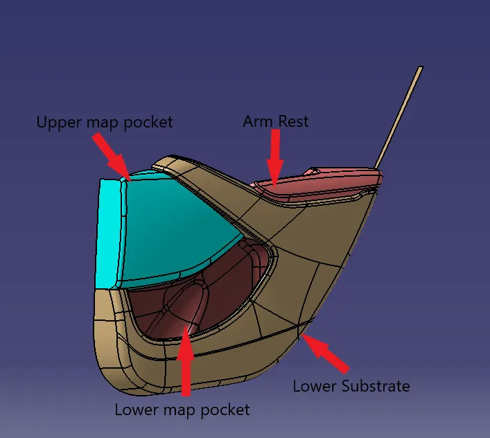
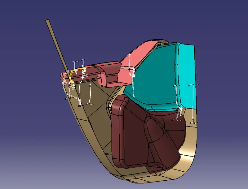
Rear side of the class A with master section
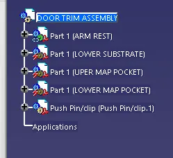
Create a product file and copy each component into different part files and name the accordingly
Creation of Tooling axis for Arm Rest :
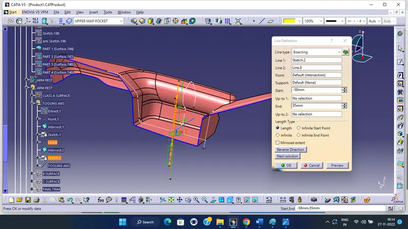
Procedure for tooling axis creation
Step 1: Insert a geometrical set . Extract the base surface and create a point at its center using point on surface option from point tool. Look for suitable axis to create a tooling axis so that all faces clear tooling .
Step 2: Create an axis system without current option ticked at the above point. Create a position sketch with zy plane from axis system and above point as reference point.
Step 3: Use intersect 3d objects option from project tool to create 2 lines by selecting a suitable plane(zy). Now create 2 lines which coincide with lines on both sides of the projection point . Create a line using bisect option .Allign the line in required axis direction.This is our Y tooling axis .
Step 4: To create tooling axis about x direction, create a position sketch with xz plane as reference plane and projection point as the first point we created . Use cut section tool and create an intersection using projection tool . Now create a line that coincides with this line .
Step 5 : Draw a line from origin in horizontal direction and create and angle constraint of 5 degrees. Use bisect option to create a line between that above lines . This is out X tooling axis .
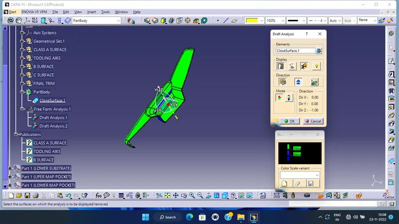
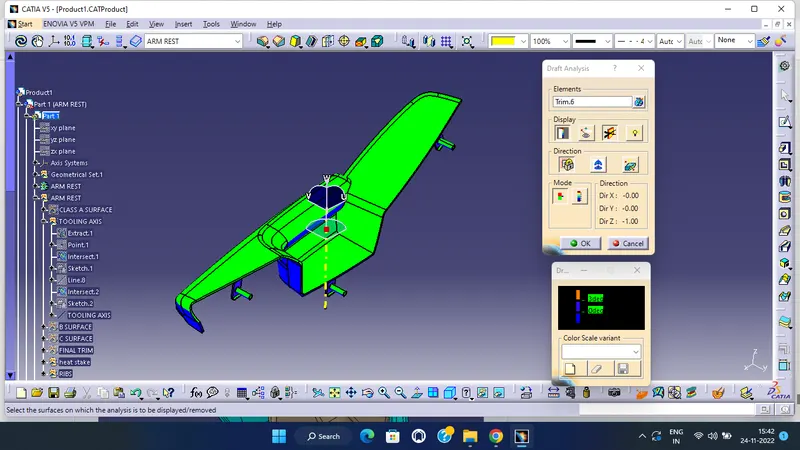
Procedure to check for Draft analysis
1)Once the tooling axis is created , publish it and the component using Publication from tool option .
2)Insert Feature draft analysis option from insert tool bar
3) Change the view option to customize view parameters and click on material option under shading .
4) Now click on the axis option from Draft analysis tools , allign it with tooling axis and click on lock option to lock it .
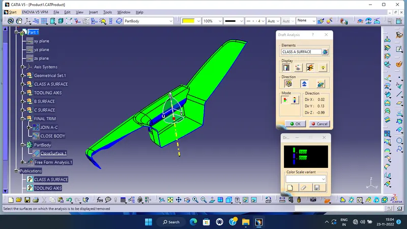
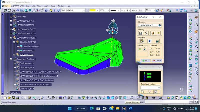
5) Change draft angle value to 3 degree . Click on quick analysis mode to display feature according to given color scale . Check from all views to ensure the draft analysis is cleared .
6) Since the created tooling axis does not clear the draft analysis at the created axis , click on the lock axis button to unlock it . Now rotate the tooling axis by left clicking on the top round portion of the axis system . Rotate the axis till maximum clearance is obtained . Now right click on the axis and click lock current axis .
7) Create a line using the initial axis origin and this axis using point and direction (using compass direction) option . This is our required tooling axis .
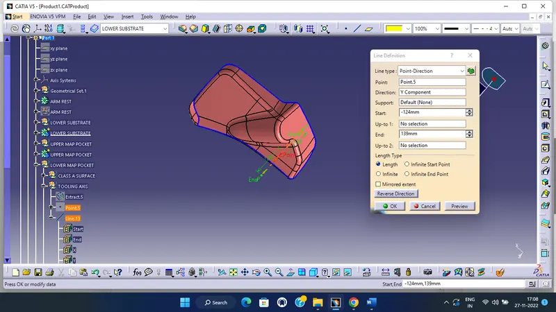
8) Now if we check for draft analysis, we can observe that the ribbed area has not yet cleared draft analyisis. Hence we need to create a side core tooling axis . To do this , create a line using point and direction option with Y direction .
9) Repeat steps 1 to 5 to ensure the remaing portion which was not cleared using Tooling axis has been cleared using this axis .
B SURFACE CREATION
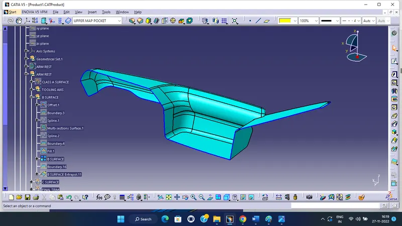
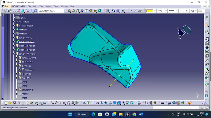
A surface offset to 2.5 mm get b surface
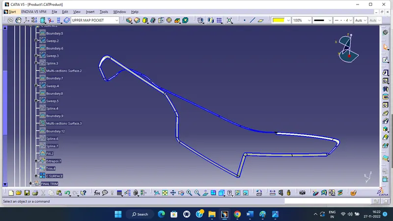
C SURFACE
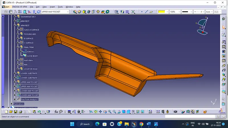
FINAL AMR REST
DRAFT ANALYSIS
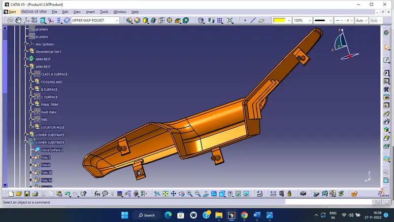
B SIDE FEATURES
DRAFT ANALYSIS
 Lower substrate:
CLASS A
TOOLING AXIS CREATION:
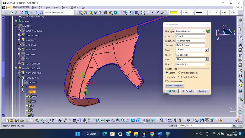
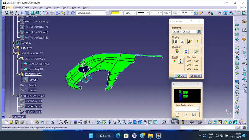
DRAFT ANALYSIS:
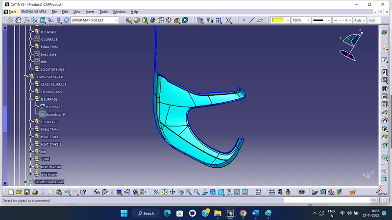
B SURFACE:
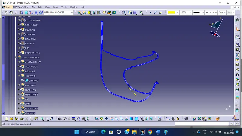
C SURFACE:
FINAL LOWER SUBSTRATE:
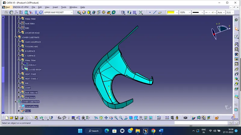
DRAFT ANALYSIS:
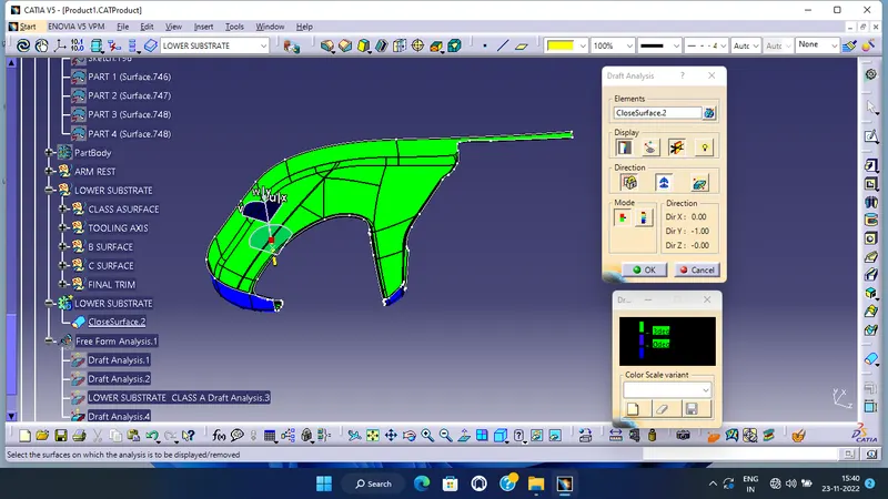
LOWER SUBSTRATE WITH B SIDE FEATURES:
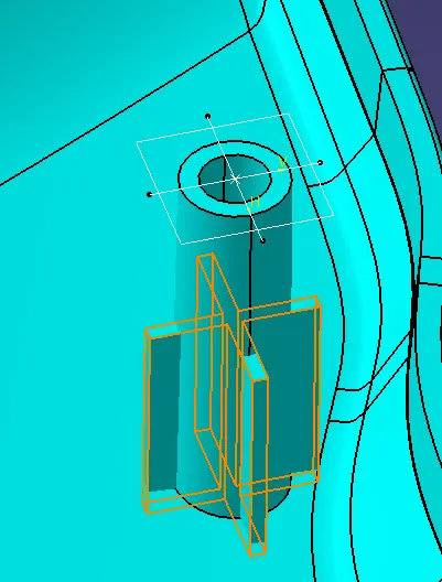
Procedure to create ribs on Heat stakes
Step 1: Create a sketch with center as centre of heat stake inner circle .
Step 2: Use pad option to create solid body
Step 3: Use boolean opetaion union trim to obtian required ribs.
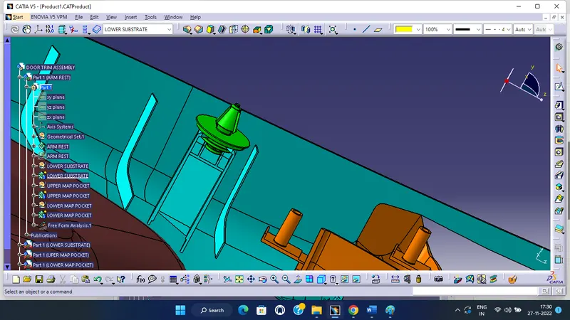
Creation dog dog house and additional attachment features according to industry standards.
Procedure to create dog house on lower substrate
Step 1: Create a point on required location and a plane from it . Create a sketch with base sketch for dog house .
Step 2: Use sweep tool to create a surface using this profile and draft direction at a draft angle of 1.5 degrees
Step 3: Use extrapolate and extrude option to create required surfaces and use trim and split to obtain the outer body of dog house .
Step 4: Create a new body and name it as dog house 1 . Use thick surface option to create a solid of required thickness .
Step 6: Extract the inner base edge and create a surface to get the required base profile . Use thick surface to create a solid and use boolean operation to remove it from the base of dog house.
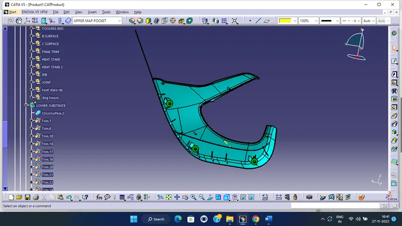
DRAFT ANALYSIS:
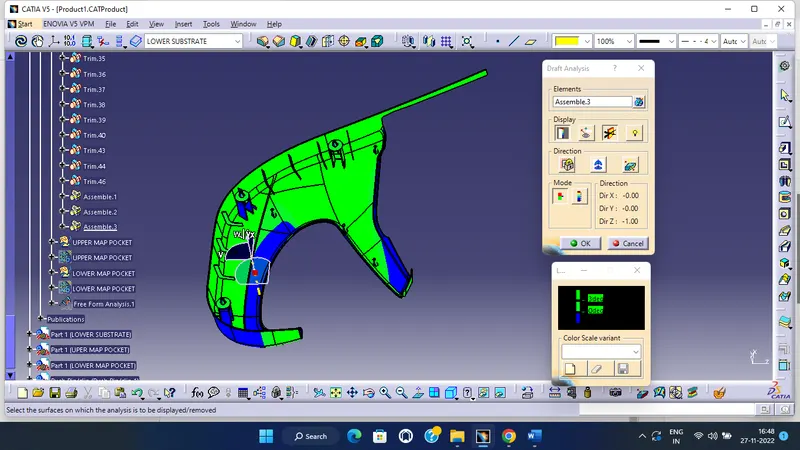
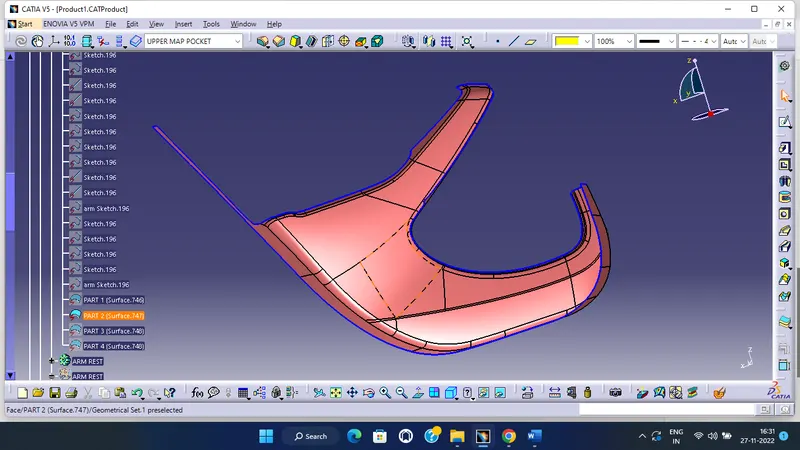
Upper Map pocket
CLASS A
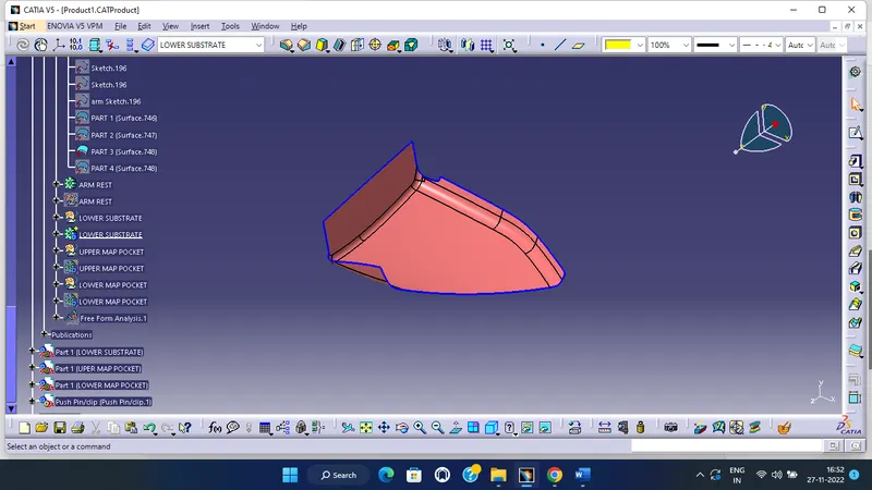
TOOLING AXIS CREATION:
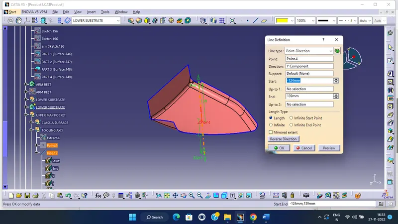
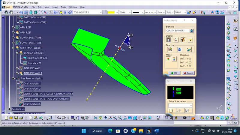
DRAFT ANALYSIS:
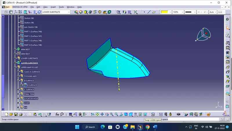
B SURFACE:
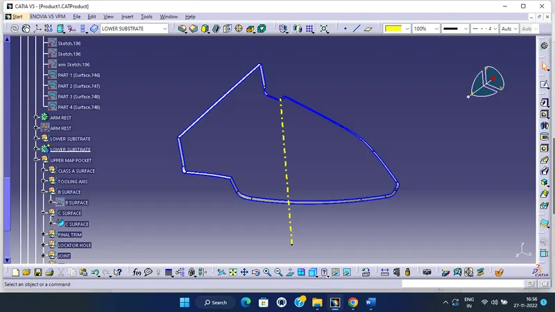
C SURFACE:
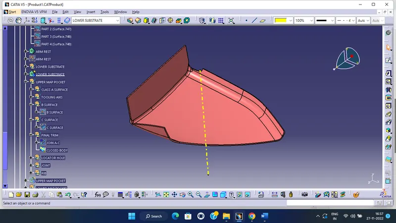
FINAL UPPER MAB POCKET:
DRAFT ANALYSIS:
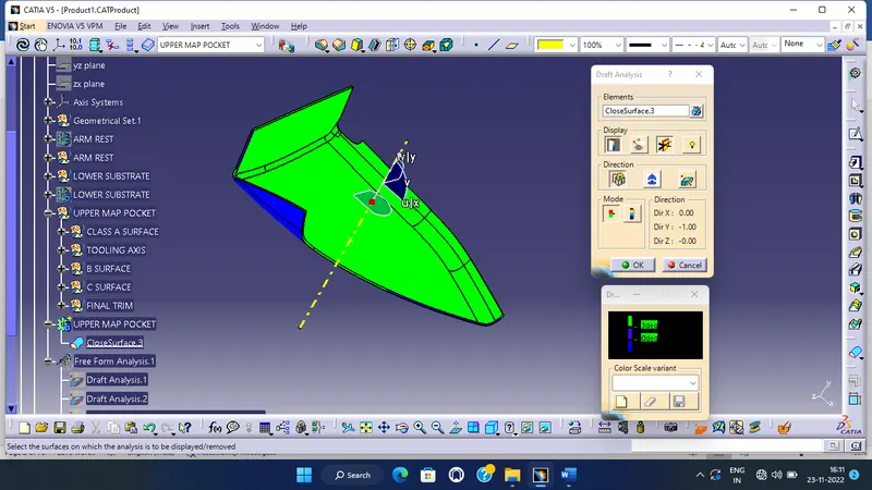
UPPER MAB POCKET WITH B SIDE FEATURES:
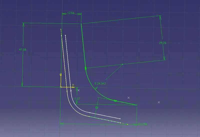
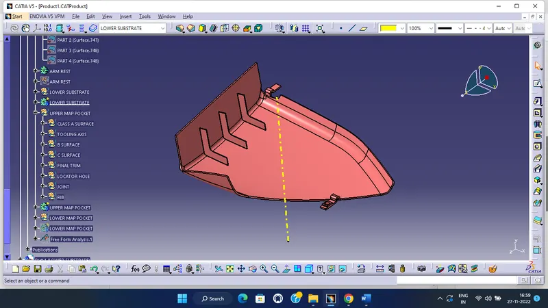
Procedure to create ribs on lower substrate
Step 1: Create a sketch and create a surface . Use thick surface option to obtain ribs in required shape .
DRAFT ANALYSIS:
lower Map pocket:
CLASS A:
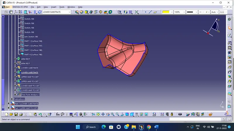
TOLING AXIS CREATION:
DRAFT ANALYSIS:
B SURFACE:
C SURFACE:
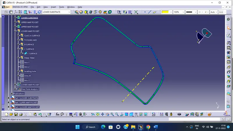
LOWER MAB POCKET FINAL:
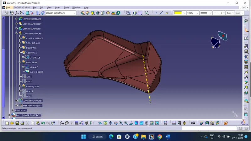
DRAFT ANALYSIS:
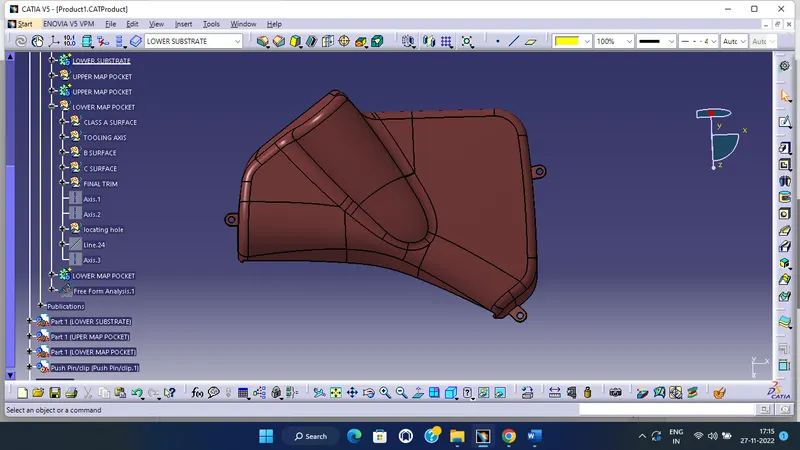
LOWER MAB POCKET WITH B SIDE FEATURES:
DRAFT ANALYSIS:
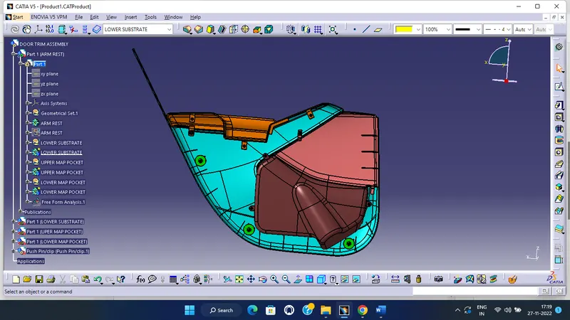
DOOR TRIM PANEL FINAL :
CONCLUSION :
Class-B and Class-C Surfaces are created to the given Class-A surfaces. The design of B-side features is done and they are assembled successfully. A detailed report has been prepared and all the part bodies and assembly has been attached to the Project successfully.