Week 11 - Final project
Aim: Development of a Door Trim panel.
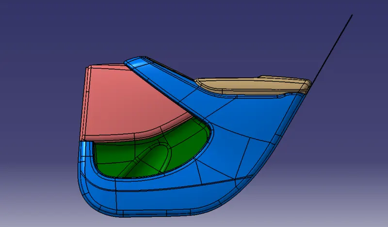
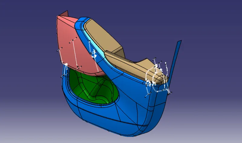
OBJECTIVE: objective for this project is to make half of the door trim panel in catia-V5 from the provided Class-A surface of the same.
ABSTRACT: This report contains a brief theory on design rules and the approach followed to achieve the final plastic product. Draft analysis report on all the class-A surface apart from the procedure to make the class-B and class-C surface is also mentioned.
INTRODUCTION:
Door panels serve as an interface between the interior of the car and the inner workings of the door, and between vehicle occupants and the door. They are expected to meet a variety of design specifications regarding safety, aesthetics, and functionality. In addition, they are expected to continue the material theme of the dashboard and pillars while concealing intricate electrical and mechanical components for operating locks, windows, and other features. The door panel has evolved from a simple two-part system of latch and simple winding mechanism to a more sophisticated enclosure. Doors currently have an inner full-width panel consisting of electronic windows, central locking system, and speakers. These panels typically consist of a foamed core covered with either textiles or plastics.

APPROACH:
Our basic approach to make a plastic model from class-A surface should be:
- Run draft analysis
- Make tooling axis
- Make B surface
- Make C surface
- Trim all together and make it solid.
CLASS-A SURFACE:
In automotive industry various teams works on various components, a car for example is not entirely designed by a single designer. There are many teams among which the task of making various components is distributed. And this is followed for every department of the industry. In this project we are given class-A surface which is designed in other software like Autodesk Alias, by a class-A designer. This is aesthetic surface and a lot of time, effort and good experience are demanded for making this continuous and a good flowing surface model. This is the major reason why, when we get this as input we are not allowed as a plastic designer to make any improvements in the class-A surface. Rather, it should be brought to the attention of the seniors which later is conveyed to the concerned team and take care of.
Theory:
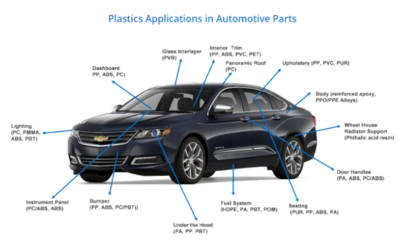
Role of plastics in the Automotive industry
The automotive industry is the third most important consuming sector of polymers after packaging and building and construction.
The role of plastic in the design and manufacturing of automotive vehicles has never been more essential, with stringent regulations and changing consumer habits driving demand for more affordable, lightweight, and fuel-efficient vehicles. Fuel efficiency has become one of the most important features in automotive vehicle design due to the rising fuel prices and stricter environmental regulations.
There are about 30,000 parts in a vehicle, out of which 1/3 are made of plastic. In total, about 39 different types of basic plastics and polymers are used to make an automobile. More than 70% of the plastic used in automobiles comes from four polymers: polypropylene, polyurethane, polyamides and PVC. Plastic has become one of the key materials required for the structure, performance, and safety of automobiles in recent years, with growth in plastic consumption being driven by light-weighting trends for fuel efficiency and consequently lower greenhouse gas emissions.
Manufacturing Process:
Injection Moulding:
Injection moulding is one of the most commonly used production processes for plastics. It offers a viable solution for the mass production of high-quality injection automotive parts from a broad range of polymers. In the automotive industry, where consistency, safety, and quality are of utmost importance, automotive plastic injection moulding is an important manufacturing process.
Plastic injection moulding is the process of melting plastic pellets that once malleable enough, are injected at pressure into a mould cavity, which fills and solidifies to produce the final product.
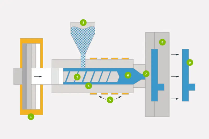
From left to right, the components of a rapid injection moulding press include ram (1), screw (2), hopper (3), barrel (4), heaters (5), materials (6), nozzle (7), mould (8), and part (9).
Tooling Direction
Tooling direction is the direction the mould takes to make the part. It is basically the direction that the mould pulls apart. The mould is built in two separate pieces, a cavity side and the core side. The core pulls apart from the cavity and that is the Tooling Direction.
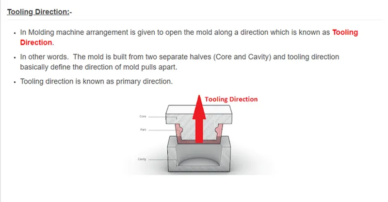
Core is the male part which forms the internal shape of the moulding. Cavity is the female part that forms the external shape of moulding.
PARTING LINE:
- A parting line is the line of separation on the plastic part where the two halves of the plastic injection mold meet.
- Parting lines cannot be avoided, every part has them. Keep in mind when considering plastic part design that the melt will always flow towards the parting line because it is the easiest place for the displaced air to escape.
- parting line plays major role in avoiding undercuts.In order to remove the plastic part from the mold, and to load the movable core or inserts into the mold body, the mold must be divided into two or more parts. Generally, the mold structure is roughly divided into two main parts: fixed half and moving half. When the mold body is closed, the contact surface of the cavity and core plates makes a parting line.
- Usually the parting line of the mold is perpendicular to the mold opening direction of the injection molding machine. When opening the mold, eject or remove the cooled and solidified plastic parts from the mold (or automatically drop), and then remove the debris in the mold cavity, or place the insert to movable core in the mold cavity.
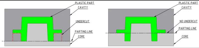
Design for Manufacturing & Assembly (DFMA)
Design for Manufacturing and Assembly is an engineering methodology that focuses on reducing time-to-market and total production costs by prioritizing both the ease of manufacture for the product’s parts and the simplified assembly of those parts into the final product – all during the early design phases of the product lifecycle.
Before becoming the singular philosophy it's known as today, DFMA used to be considered as two distinct methodologies: Design for Manufacturing (DFM) and Design for Assembly (DFA).
DFM is concerned with selecting cost-effective raw materials and attempting to minimize the complexity of manufacturing operations during the product design phase in order to reduce the overall manufacturing time and costs for product components. Similarly, DFA is concerned with reducing the product's assembly time, costs, and complexities by minimizing the number of individual parts, assembly steps, and the potential for variability in build quality.
Function of Heat Stake, Locator, Doghouse, and Ribs
Heat staking technology is quite simple in concept. Whenever two or more components need to be attached to one another, and at least one is made of a thermoplastic, a combination of heat and pressure can be used to reform the plastic to the many shapes or profiles to retain or join the parts together.
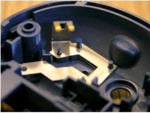
Heat Stake (cylindrical structure on the left)
A 2-way locating pin restricts motion along 1 axis (or 2 degrees of Freedom). Likewise, a 4-way pin restricts 4 degrees of freedom along 2 axes.
Dog house is a 4 sided box attached to a flat surface which usually requires a riser/slider to mould. In other words, it has 3 sides and a roof, where the roof usually has a hole for attachment purposes.”
Ribs can be added to parts to add rigidity or stiffness. Adding ribs allows for a part to increase strength and bear a higher load.
DRAFT:
Draft angle is nothing but providing some tapered portion to the part for easy removal of the component from the mold during manufacturing. This is especially done in the case of plastic component design having a complex shape. Mostly the 3-degree draft angle is provided but it can vary depending upon the component which is to be designed
In our case of Switch Bezel design, the draft angle is 3 degrees the draft analysis is done during the design of the component to check the feasibility of the product.
Before providing a draft angle we need to decide on the tooling axis also known as the molding axis considering the faces which can cause issues while manufacturing.
TOOLING AXIS :
It is nothing but the direction in which the mold opens and closes the draft angle needed to be provided by considering this tooling axis.
We can create a tooling axis by using the bisecting method.
BISECTING METHOD:
This method is used for the generation of the tooling axis for that purpose first we need to decide the direction of molding and then we create one dummy tooling axis for the reference to the purpose.
In this method, we select the surfaces which can create problems and take intersections in the x and y-direction. By using these curves we draw two lines and then draw a bisecting line from these two lines in the x-direction and y-direction.
If it is done in x-direction then it is called a tooling axis clearing x-direction and if in y then tooling axis clearing y-direction.
After completing this we need to draw a final line bisecting this two tooling axis in the X and Y directions to get our final output.
Arm Rest:
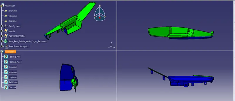
CREATING THE TOOLING AXIS:
- Check all the boundary whether it has connected or not.
- Check the model visually & choose the best tooling direction which should be easy for draft
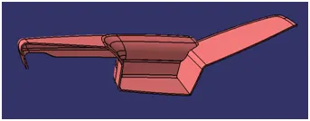
- After analyzing the above model, there is an chance for undercut when we consider tooling axis from z.so we have to create tooling axis on x,y and also z
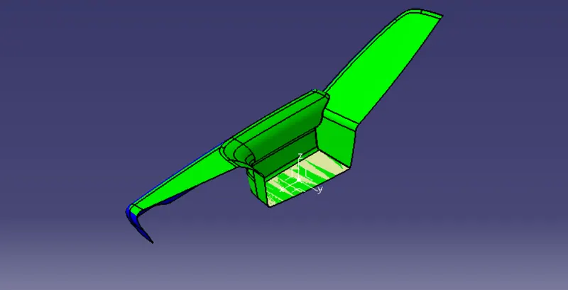
- Create a point and insert a axis system on the point 1 as shown below
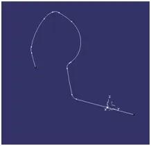
- Create a intersection on ZX plane for the given surface
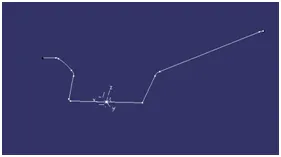
- Create a point to point line as shown below
-
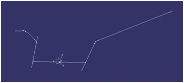
-
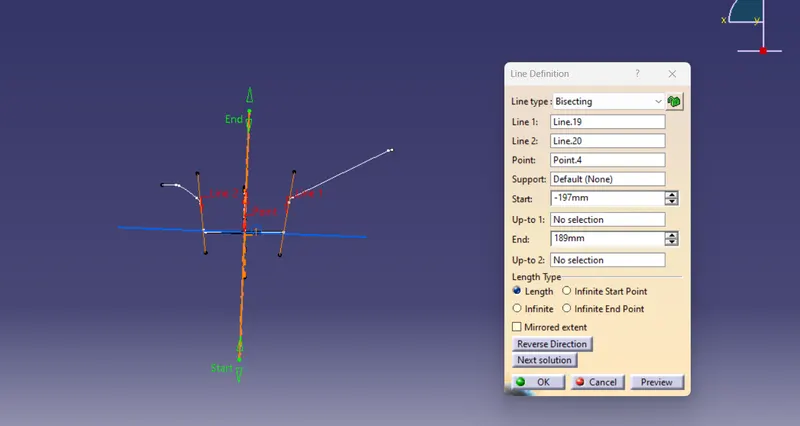
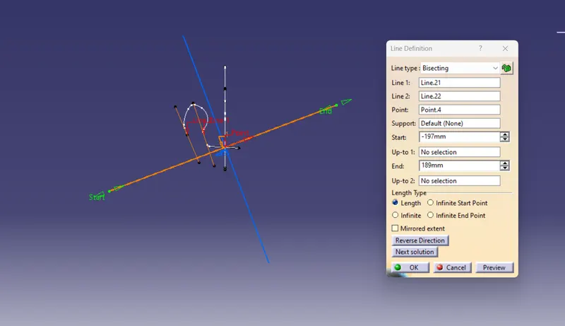
Add bisecting line as shown below by the reference of two lines created above and named as TOOLING FACING X DRIECTION
-
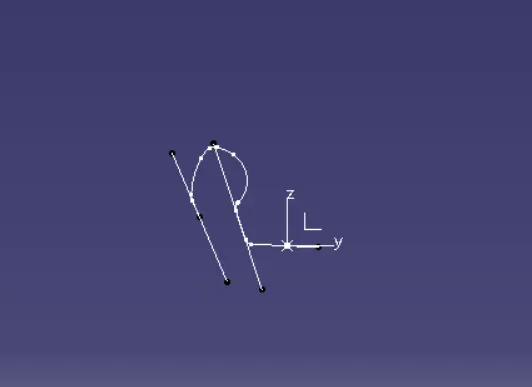
- Create a intersection on ZY plane for the given surface
- Create a point to point line as shown below
- Add bisecting line by the reference of tooling facing x direction and tooling facing y direction and named as tooling axis
Pocket Upper:
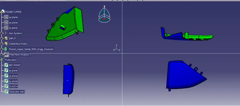
CREATING THE TOOLING AXIS:
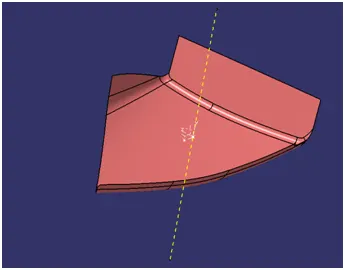
- Create a point on centre of gravity of part by using measure inertia command and insert a axis system on the point as shown below
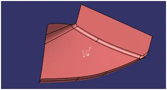
- create a point -direction line parallel to the y axis and named as TOOLING AXIS as shown below
Pocket Lower:
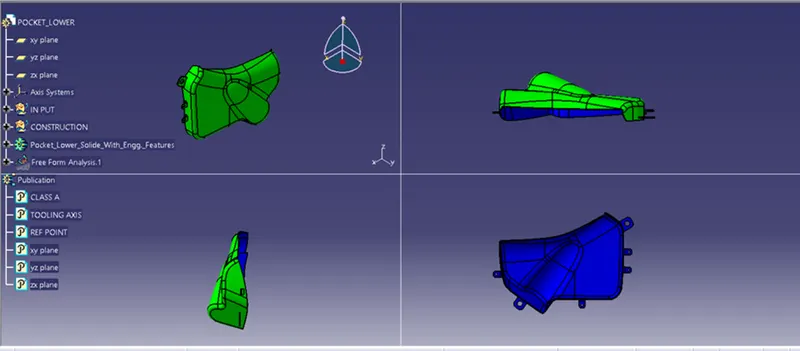
CREATING THE TOOLING AXIS:
- Check all the boundary whether it has connected or not.
- Check the model visually & choose the best tooling direction which should be easy for draft.
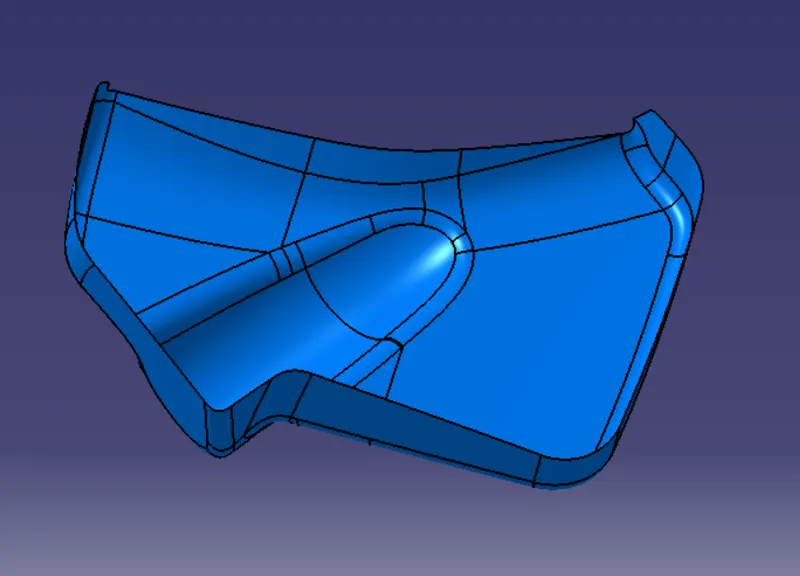
- After analyzing the above model,we have to create tooling axis on Y
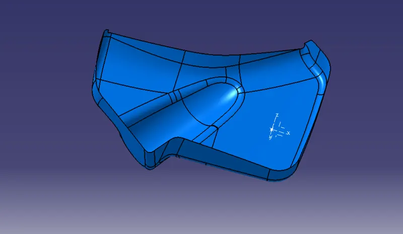
- Create a point 1 and insert a axis system on the point 1 as shown below
- Create a intersection on XY plane for the given surface
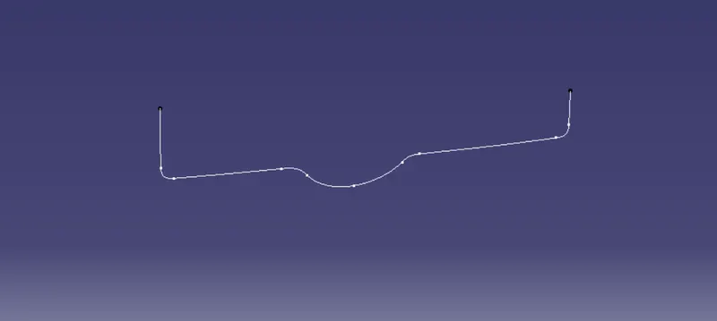
- Create a point to point line as shown below
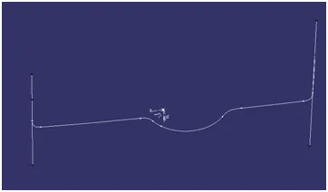
- Add bisecting line as shown below by the reference of two lines created above.
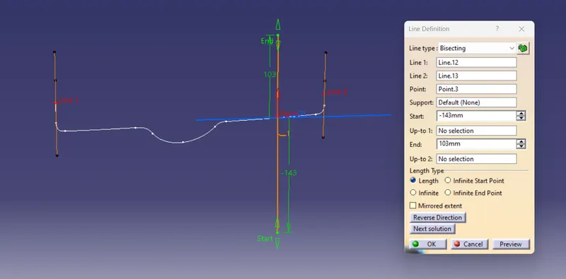
- Create a intersection on ZY plane for the given surface
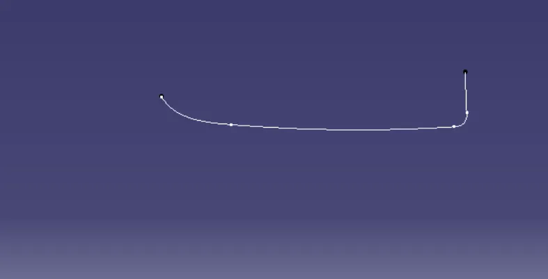
- Create a point to point line as shown below
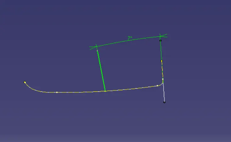
- Add bisecting line as shown below by the reference of two lines created above and named as TOOLING FACING Y DRIECTION
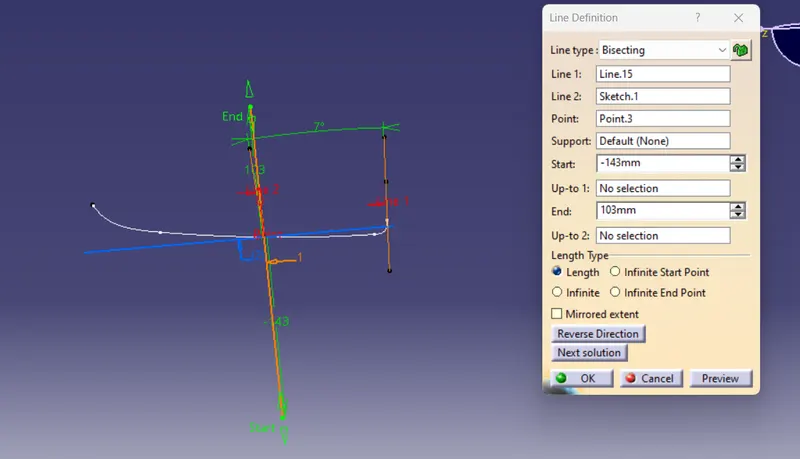
- Add bisecting line by the reference of tooling facing x direction and tooling facing y direction and named as tooling axis
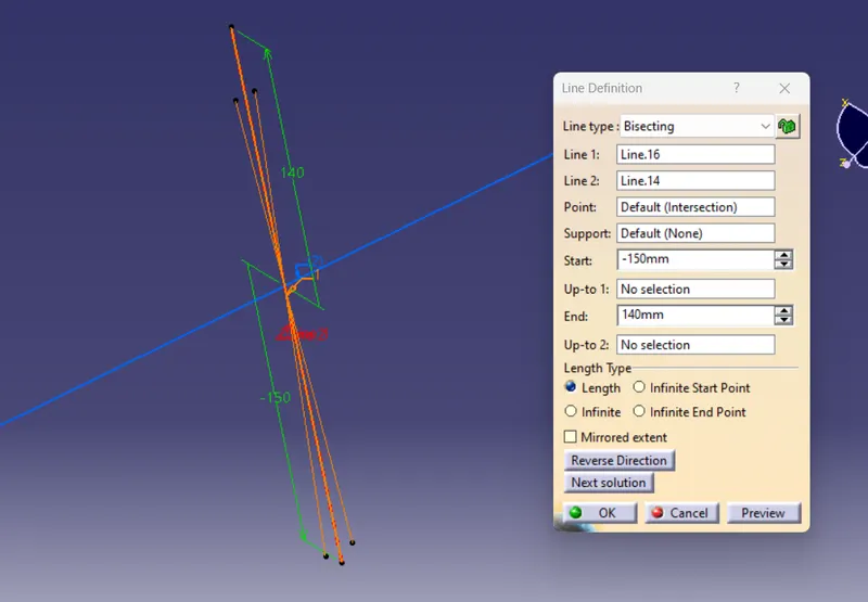
Lower Subtrate:
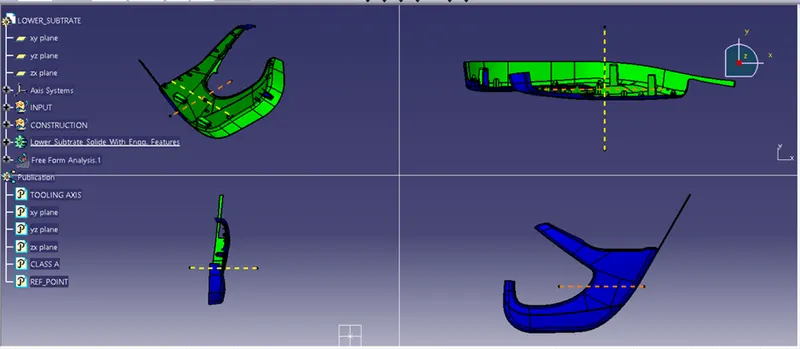
Creating Tooling Axis:
- Check all the boundary whether it has connected or not.
- Check the model visually & choose the best tooling direction which should be easy for draft.
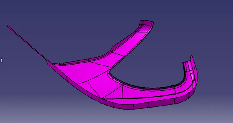
- After analyzing the above model the best tooling axis is y direction.
- Create a point on centre of gravity of part by using measure inertia command and insert a axis system on the point as shown below
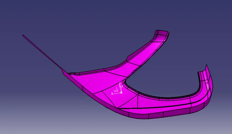
- create a point -direction line parallel to the y axis and named as TOOLING AXIS as shown below
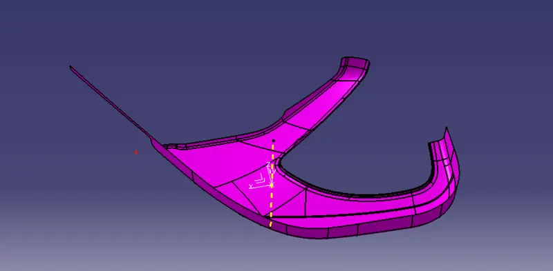
PERFORMING DRAFT ANALYSIS ON MODEL
- To perform draft analysis open customize view parameters and choose the material
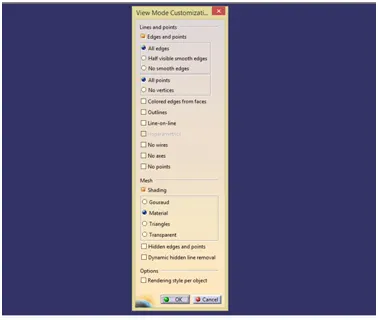
- Insert a feature draft analysis by following these commands
- insert>analysis>feature draft analysis
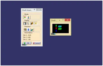
- Align the compass on tooling axis that we created
- Open the color scale and enter the value is 3 deg.
- If the whole body is green that all the faces is great angle than the provided angle
DRAFT ANALYSIS REPORT OF CLASS A – ARM REST
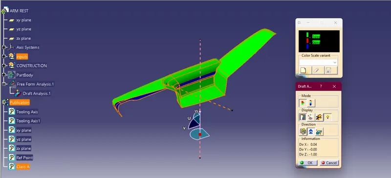
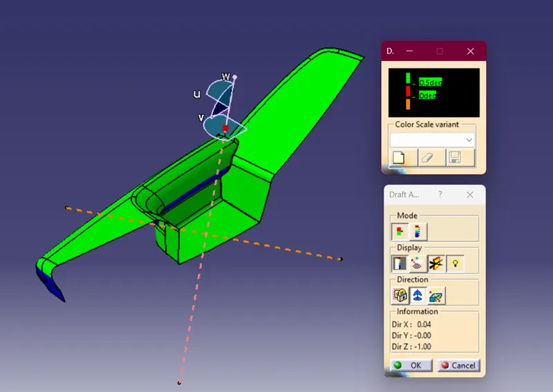
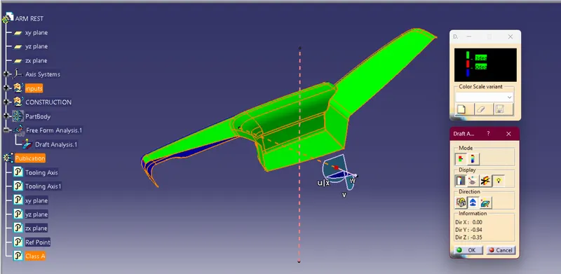
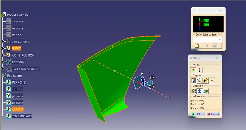
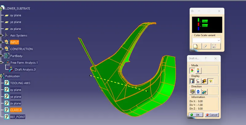
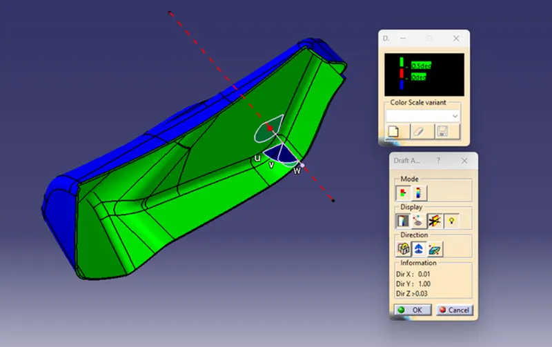
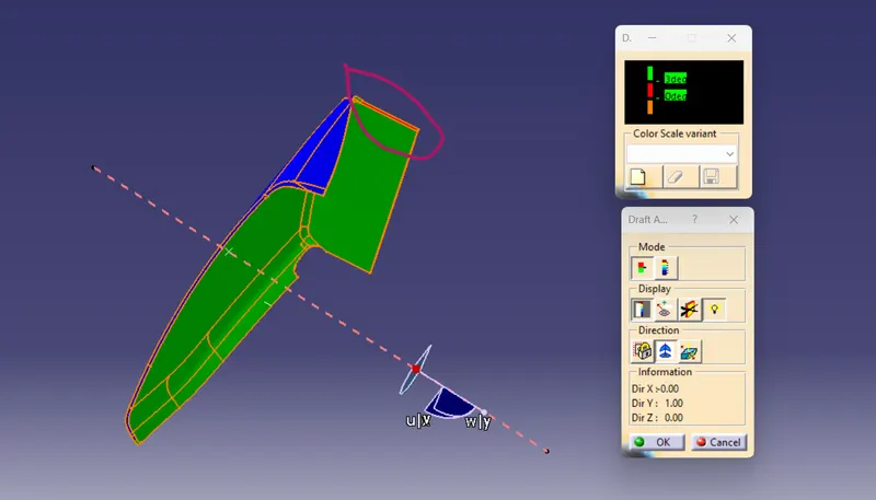
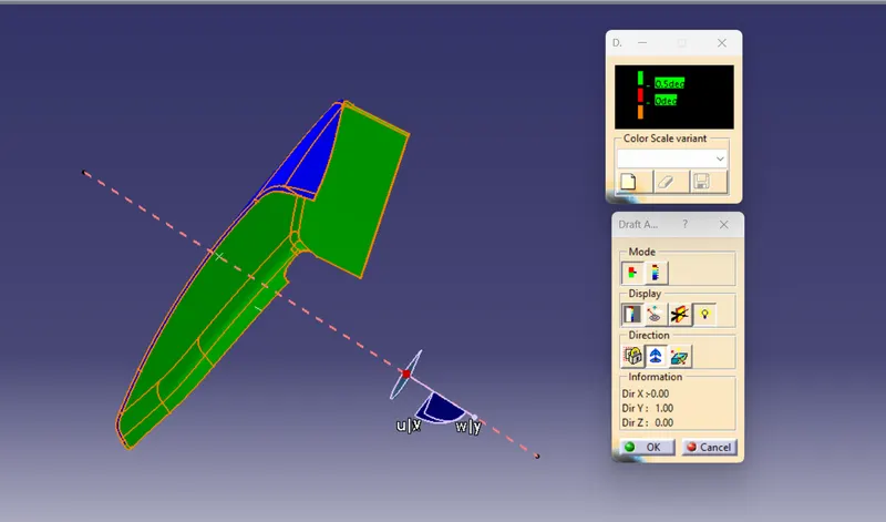
The above image shows the draft analysis in which green color surfaces shows that they are having an angle of more than 3 degrees but the surface in red color shows it is less than 3 degree that is having an angle of 0.5 degrees. These are the results of the draft analysis which are very crucial for determining the feasibility of the product.
DRAFT ANALYSIS REPORT OF CLASS A – Pocket Lower:
3 Degree
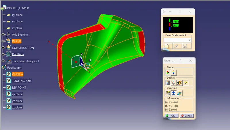
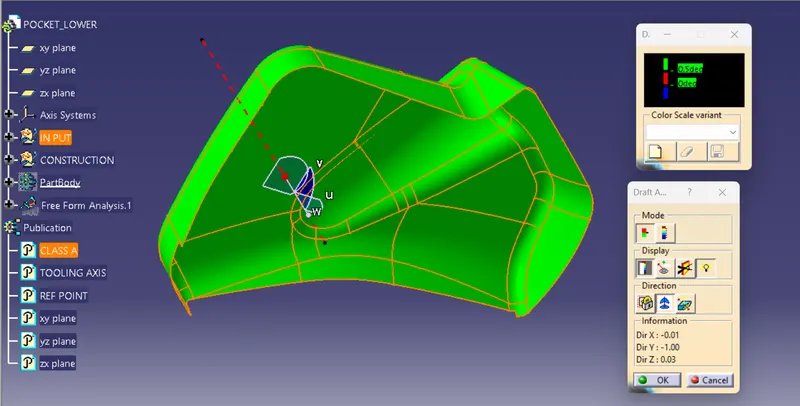
The above image shows the draft analysis in which green color surfaces shows that they are having an angle of more than 3 degrees but the surface in red color shows it is less than 3 degree that is having an angle of 0.5degrees. These are the results of the draft analysis which are very crucial for determining the feasibility of the product.
0.5 Degree:
DRAFT ANALYSIS REPORT OF CLASS A – Pocket Upper:
DRAFT ANALYSIS REPORT OF CLASS A – Lower Subtrate:
DESIGNING PLASTIC COMPONENT
As the entire door panel is divided into various components, we will make this plastic component in the same way. Following steps have been carried out to make the plastic component for every component:
The first step for every component was same. The given input was not a single unit but has numerous patches. These patches were joined together using join command. Thus after performing this operation we got our single class-A surface.
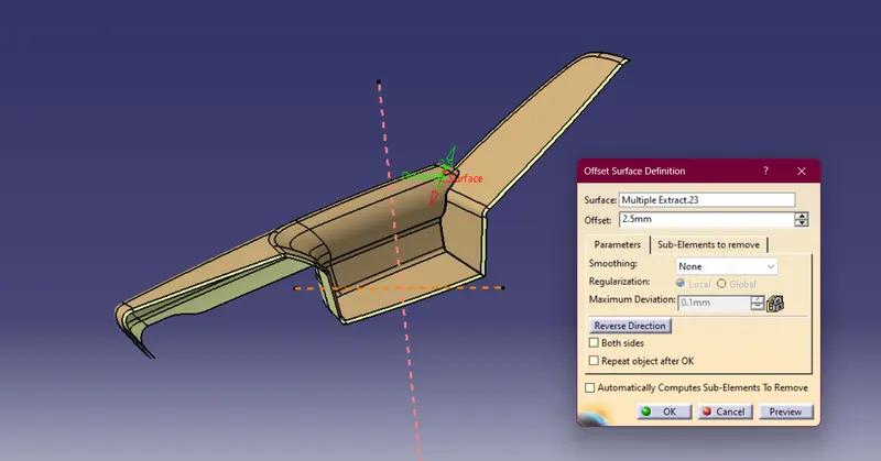
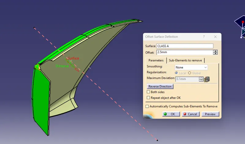
Once we get class-A, we have to proceed to make class-B surface. Creating class-B by extracting every flat surface will be a complex process in such component. So we directly offset it by 2.5mm.
For making class-C surface we have used sweep command ‘with draft direction’ by giving 3deg draft angle and tooling axis as direction. But at many places this did not work so we have to sweep ‘with reference surface’ at 90deg. Once that was done, the C surface was joined together using join command.
To make a final surface model, we have to trim all the three surfaces together. And later go to part design to close the surface.
HERE ARE THE IMAGES OF EVERY COMPONENT IN THE ORDER OF THE ABOVE STEPS
Arm Rest:
Creating class B & C surface:
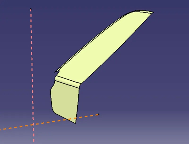
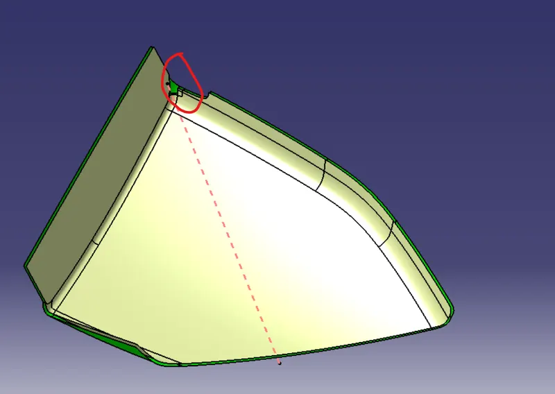
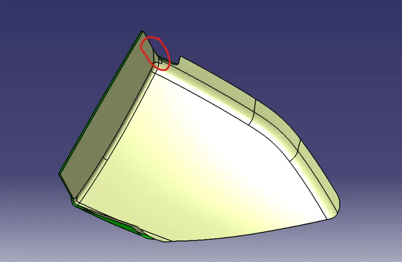
While following a general procedure, we encountered a problem with B surface. This problem was faced multiple times while making different model. When a offset of 2.5mm was given to the class-A surface, a patch of it was missing in the class-B. So we have to make that patch. This component too was divided into two parts and then Offset separately & extract both the surface using multiple extract After then use A extrapolate command after that I trimmed it together the adjacent surfaces to get a single patch and in the end joined everything together.

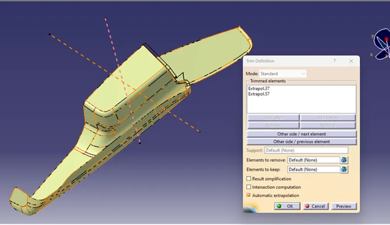
Once this was done, we move forward to make class-C surface. Like other methods, here also we used combination of both the sweeps to make class-C surface and join them together.
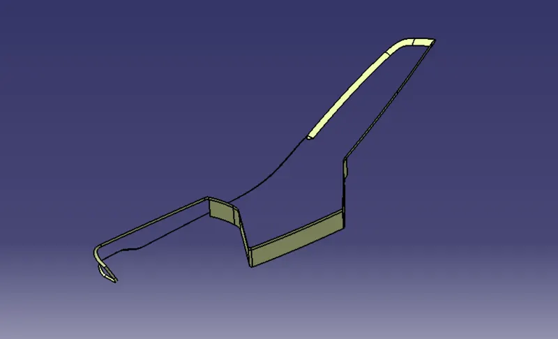
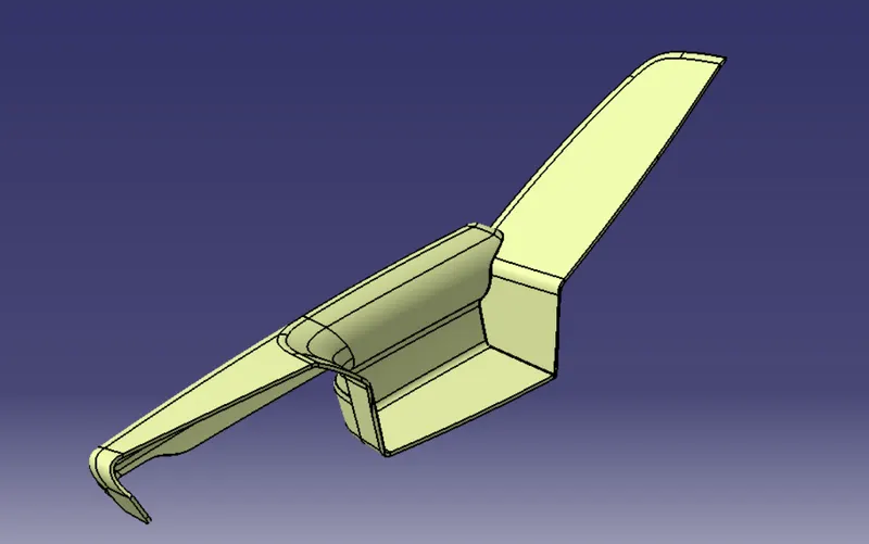
For making surface model, we have trimmed all of them together. Later it was made into solid component and draft analysis was run on it.
3 Degree:
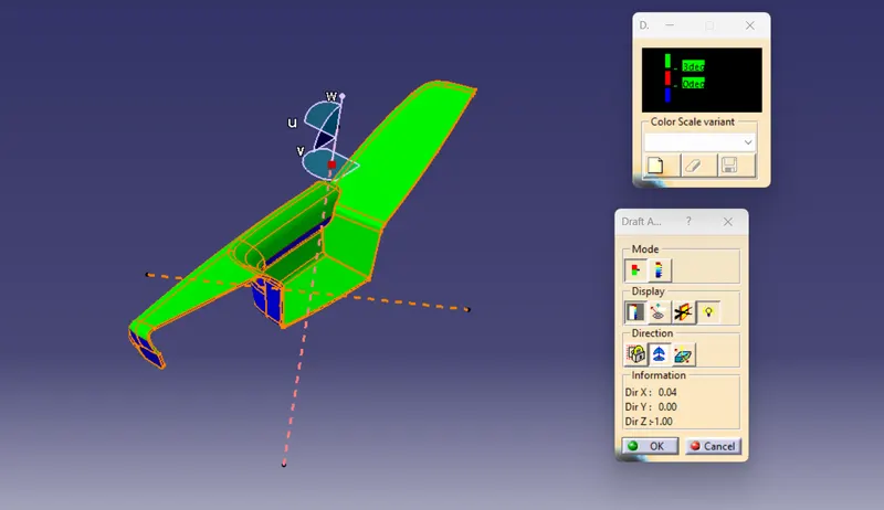
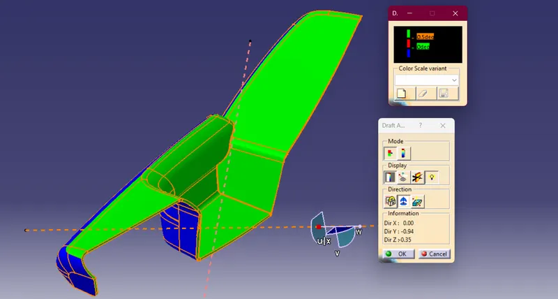
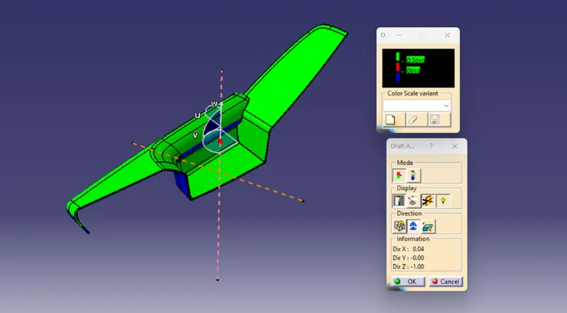
As class-A surface had problems in draft analysis, the same problem is with the component and this was expected result too. The above image shows the draft analysis in which green color surfaces shows that they are having an angle of more than 3 degrees but the surface in red color shows it is less than 3 degree that is having an angle of 0.5 degrees. These are the results of the draft analysis which are very crucial for determining the feasibility of the product.
0.5 Degree:
Pocket Lower:
Creating class B surface:
We have divided map holder into two different parts, upper map holder and lower map holder, and worked on them separately.
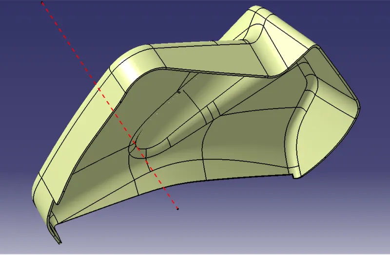
Pocket Lower
After joining class-A surface together, it was offset at a distance of 2.5mm to get class-B surface.
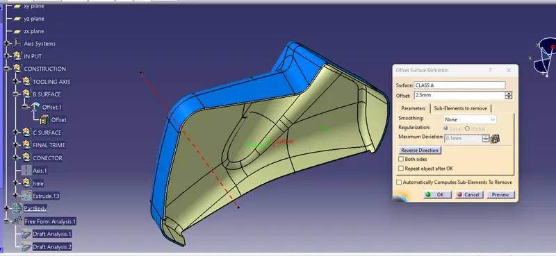
As the boundary of class-A surface is not constantly flowing in one direction and there are many round corners, sweeping along with tooling direction was creating problems, so to avoid cusps many patches of C-surface were made and later joined together.
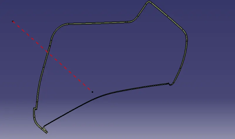
Once we get all the surfaces we have to trim all of them together to get once single closed surface model. Later we have to make it into a solid body and run draft analysis on the component.
3 Degree:
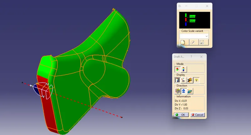
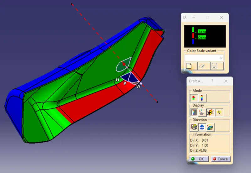
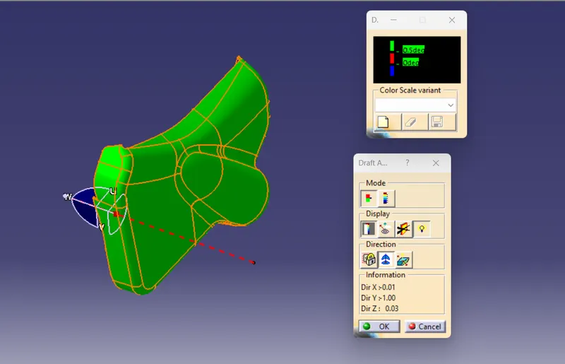
As class-A surface had problems in draft analysis, the same problem is with the component and this was expected result too. The above image shows the draft analysis in which green color surfaces shows that they are having an angle of more than 3 degrees but the surface in red color shows it is less than 3 degree that is having an angle of 0.5 degrees. These are the results of the draft analysis which are very crucial for determining the feasibility of the product.
0.5 Degree:
Pocket Upper:
Creating class B & C surface:
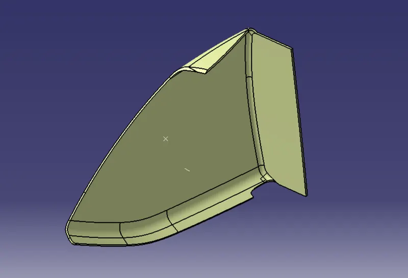
While following a general procedure, we encountered a problem with B surface. This problem was faced multiple times while making different model. When a offset of 2.5mm was given to the class-A surface, a patch of it was missing in the class-B. So we have to make that patch. A spline was created between the ends where the patch was missing and a patch of surface was created usind multisection surface. After that, we trimmed the adjacent surfaces to get a single patch and in the end joined everything together. Below images shows class-B with missing patch and final class-B surface and. The blue thick line in the second image is the spline.
Once this was done, we move forward to make class-C surface. Like other methods, here also we used combination of both the sweeps to make class-C surface and join them together.
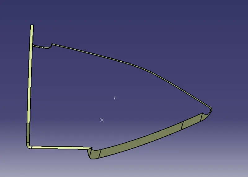
For making surface model, we have trimmed all of them together. Later it was made into solid component and draft analysis was run on it.
3 Degree:
0.5 degree:
LOWER SUBSTRATE:
Creating class B & C surface:
joining the class-A surfaces together so that it is easy to offset it for getting class-B surface.
Class-B surface was created by offseting class-A surface by 2.5mm distance. This is the nominal thickness of the component.
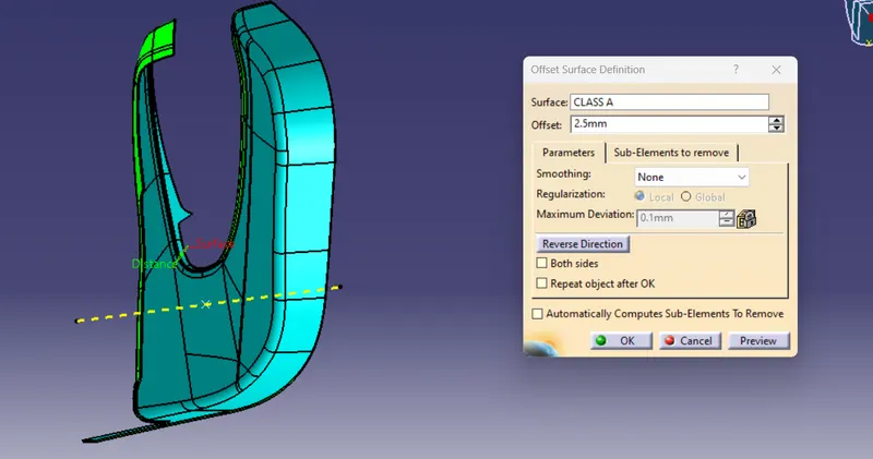
Class-C surface was created by sweeping it along tooling axis at some part and sweeping it with reference surface at other. In the end every patch was joined together to get class-C surface.
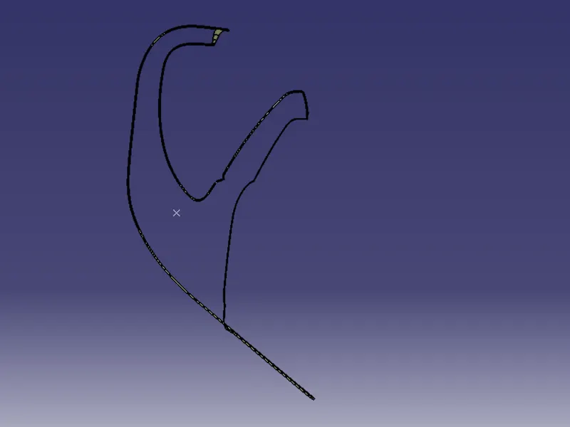
Final surface model was created by joining class-A and class-C surfaces together and later trimming them with class-B surface.
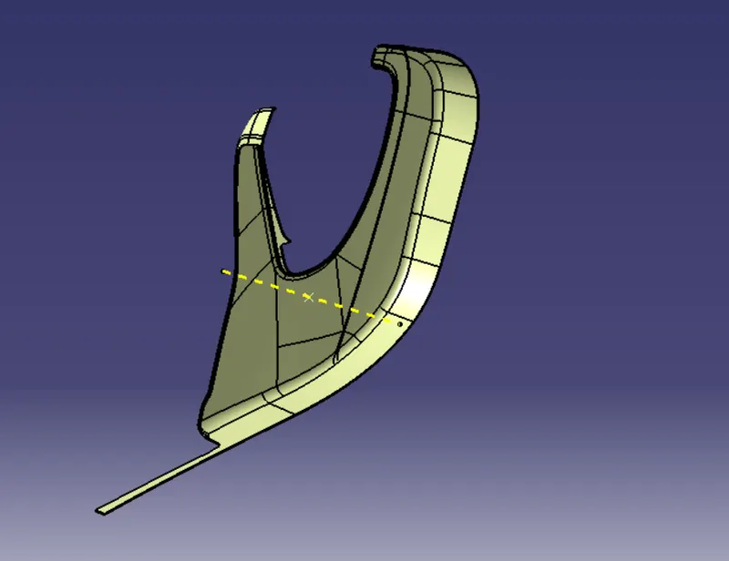
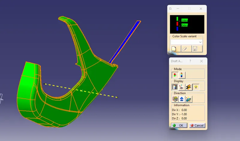
Once we get the surface model, we make it into solid model by going to part design and closing the surface. Once that is done, we run a draft analysis on the component and once it is clear, we move ahead with making B-side features and again run a draft analysis on the entire component. Below image shows the analysis on lower substrate component after making all the features.
3 Degree:
DESIGNING B-SIDE FEATURES
DOG HOUSE: Primary function of the dog house is to avoid sink marks. But it also helps in other things like if the mating part is to be at a greater distance then we cannot make the height of the screw boss of that greater height, thus we make dog house and mount screw boss on it. Hence it helps in solving the problem of screw boss and also it helps to have perpendicular screw boss.
GENERAL DESIGN GUIDELINES FOR DOG HOUSE DESIGN:
Minimum height of B surface to coring should be between : 3mm to 6mm.
Draft: minimum 1.5deg.
Sink saver: height= 40% of nominal thickness.
Optimal radius:25mm
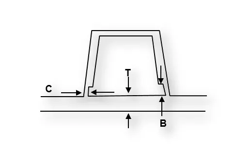
However, for this model we made a dog house which mounts push pins on it. Every above design rules were followed while making the dog house.
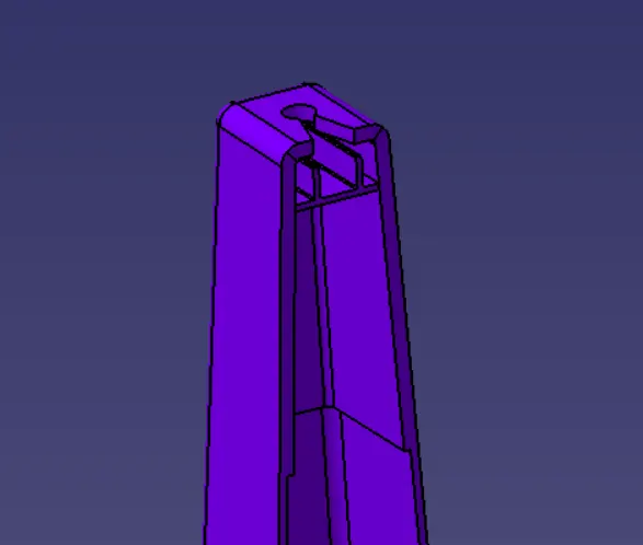
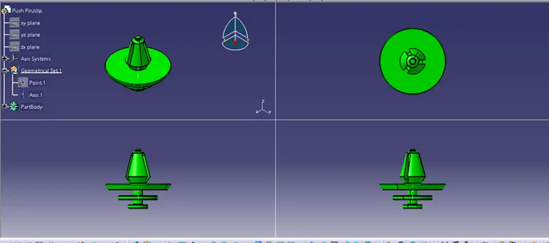
Push clips are mounted on this dog house. But as the push clips are manufactured else where and is not in our zone of concern so we have ignored the rules while making the push clips and made a general clip of similar shape in part design without following any rules.
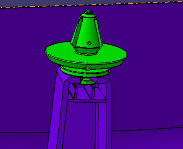
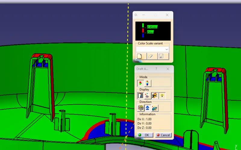
DRAFT ANALYSIS ON DOG HOUSE
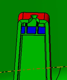
Two tooling axis were made for the dog house as there will be a side core for the inside portions of the component.
Outer surface clearing with 0.5 Deg Draft with main Tooling Axis
A side core Axis provied for the inner faces.
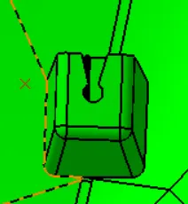
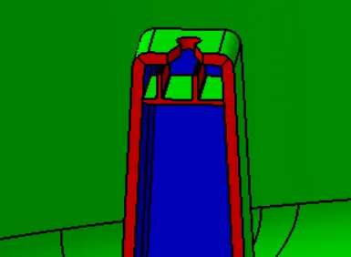
The inner faces clearing 0.45 degree draft on side core Tooling Axis
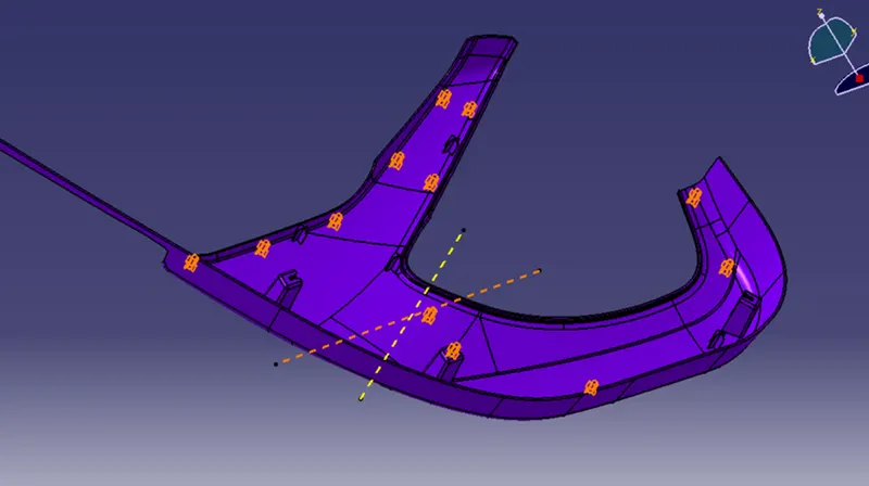
HEAT STAKES
Heatstakes is known as thermoplastic staking is the process of joining two dissimilar metals together
- Extract the surface that we going to create heat stake
- Use positiioned sketch and draw a heat stakes sketch
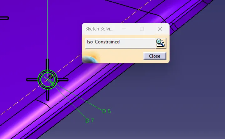
- Use pad commands for the sketch to till we required
- Draft the stakes minimum of 0.5 degree
- Add fillet 0.5mm of all faces
- Assemble the heat stake to lower subtrate solid
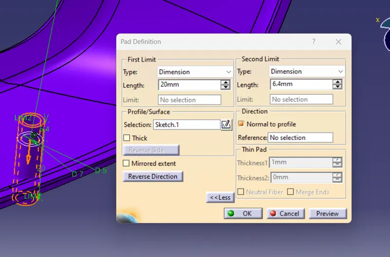
- Maintain a 50mm minimum between two heat stakes
- Translate the heatstakes to wherever we need
- Trim the all heat stakes with lowersubstrate solid
LOCATOR
- Extract the surface that we going to create locator
- Use positiioned sketch and draw a locator sketch
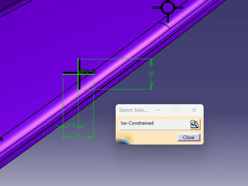
- Use pad commands for the sketch to till we required
- Draft the locator for minimum of 0.5 degree
- Add fillet 0.5mm o all faces
- Assemble the locator to lower subtrate solid
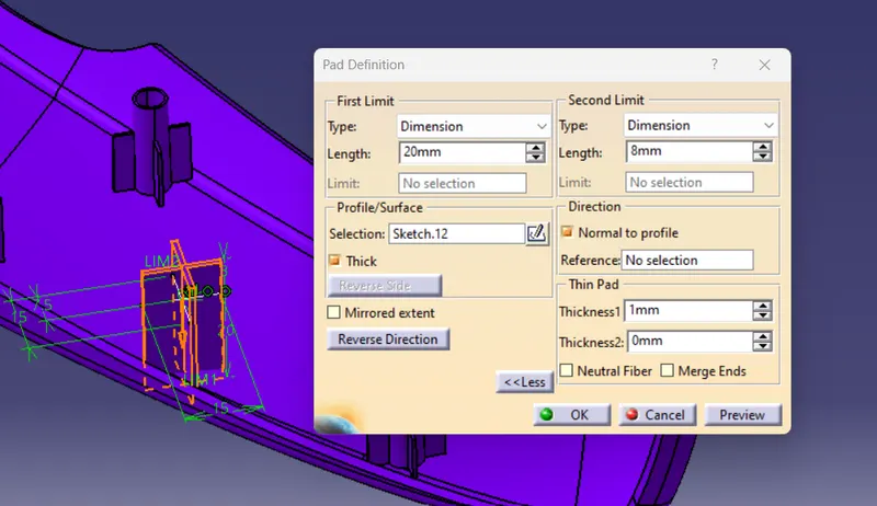
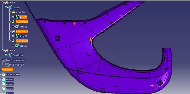
- Maintain a 50mm minimum between two locator
- Translate the locator to wherever we need
- Trim the all heat stakes with lowersubstrate solid
- Maintian a height more than heat stake
FLANGE
Creating a flange for attachment of heatstakes and locators at lower substrate
Creation of the flange was started by taking an extrude from the upper edge of the solid body and making directional changes according to the HS/locator placement.
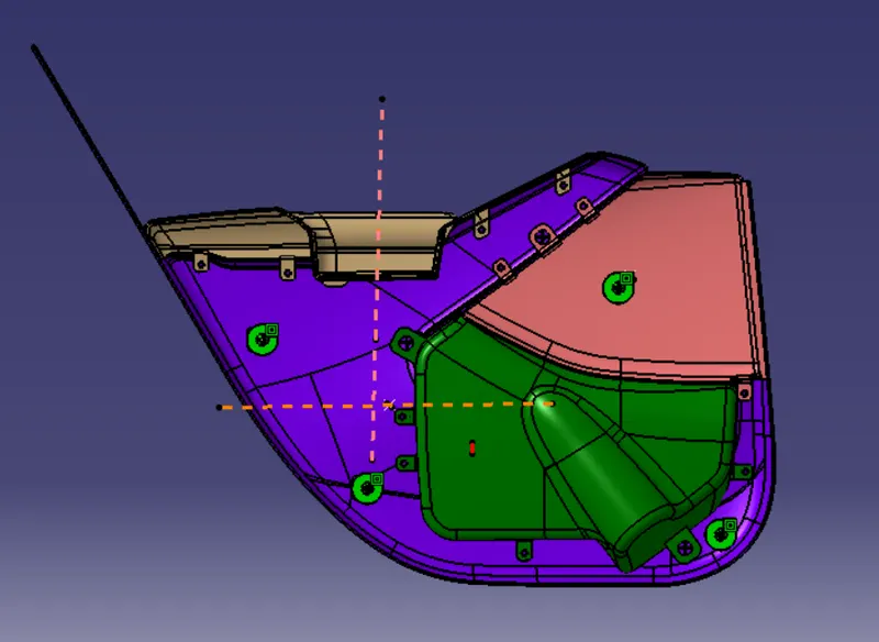
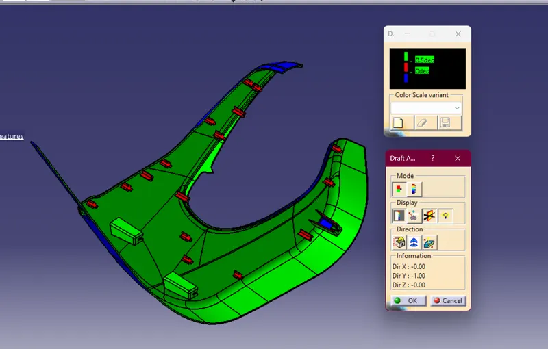
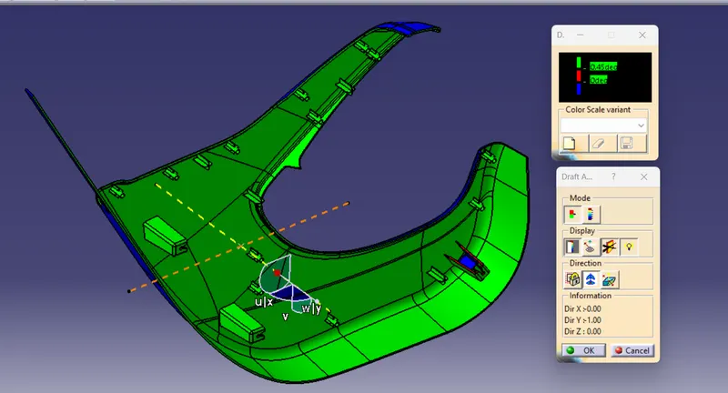
Draft analysis for B Side features:
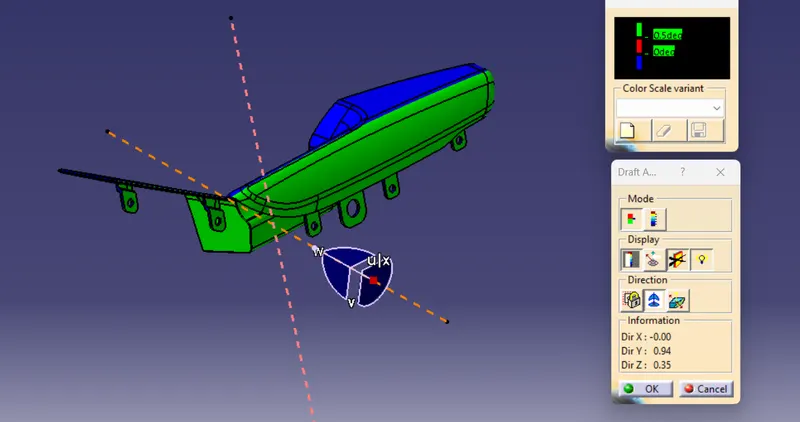
Arm Reast:
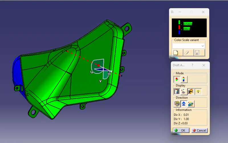
Pocket Lower:
Pocket Upper:
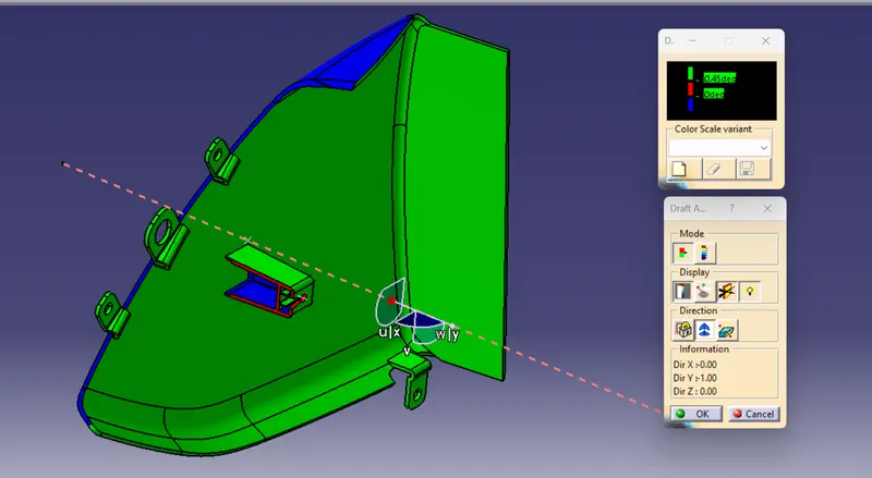
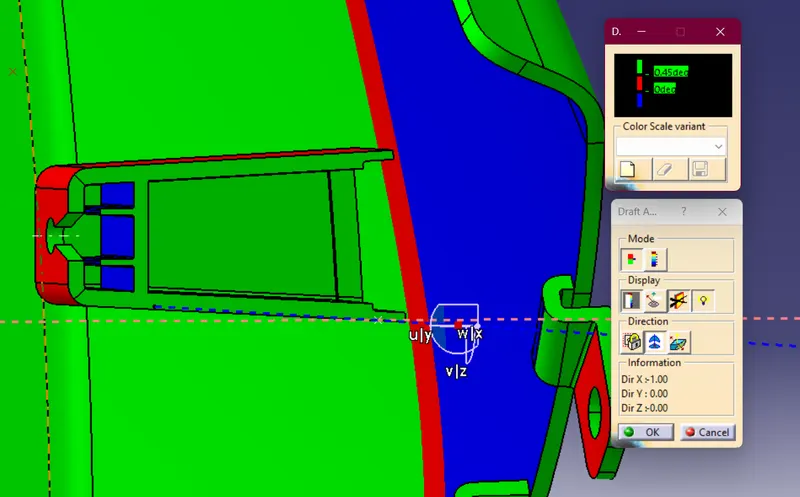
Lower Subtrate:
ISOMETRIV VIEW OF EACH COMPONENT:
ARM REST:
POCKET LOWER:
POCKET LOWER:
LOWER SUBSTRATE:
PUSH PIN:
FINAL PRODUCT:
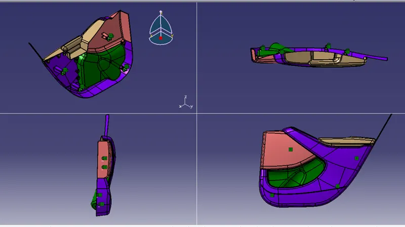
Conclusion: Hence the solid body of various parts of the door trim was made successfully with all necessary B-side features following all the design rules and guidelines.