Week 11 - Final project
FINAL PROJECT: DOOR TRIM PANEL
AIM: To design a door trim panel with the reference of given inputs and by improving class A surface and creating class B and Class C surface with tooling axis and B side features for attachment purpose with the help of master section and assemble of push pin in doghouse.
INPUTS: Class A surface, master section and push pin clip are the given Inputs.
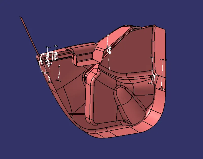
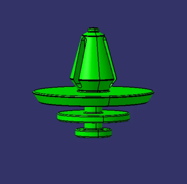
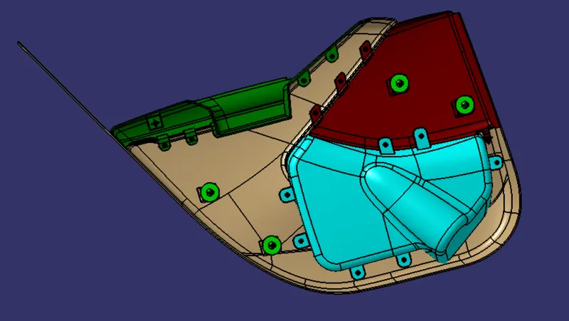
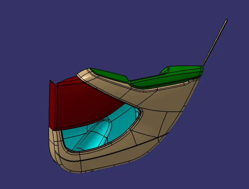
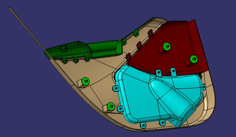
In this Cad there are 4 parts:
- DOOR ARM REST
- DOOR LOWER SUBSTRATE
- MAP POCKET
- BOTTLE HOLDER
DOOR ARM REST:
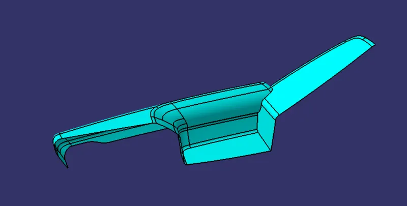
Class A Surface: First we have to check the A surface by giving boundary on it. There was some patch in the door arm rest so i have improved the A surface. The image below is improved A surface.
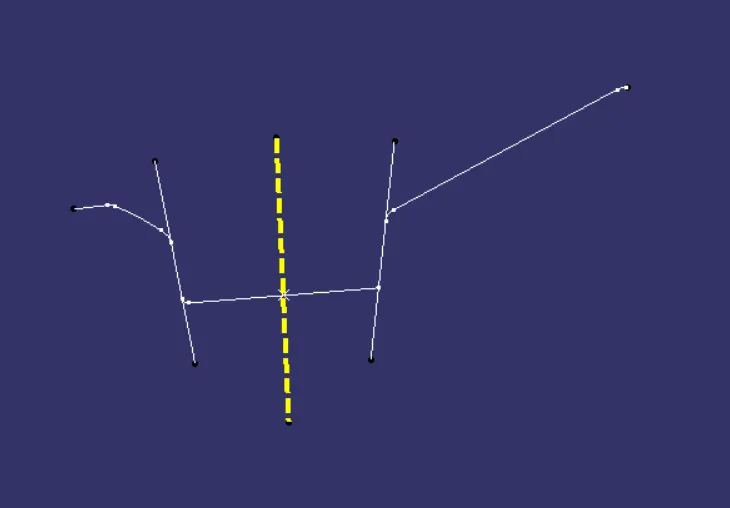
CREATION OF TOOLING AXIS: Take an intersection on the A surface by creating line on the intersection and with the help of bisecting method, create a tooling axis. The image below is the method of creation of tooling axis.
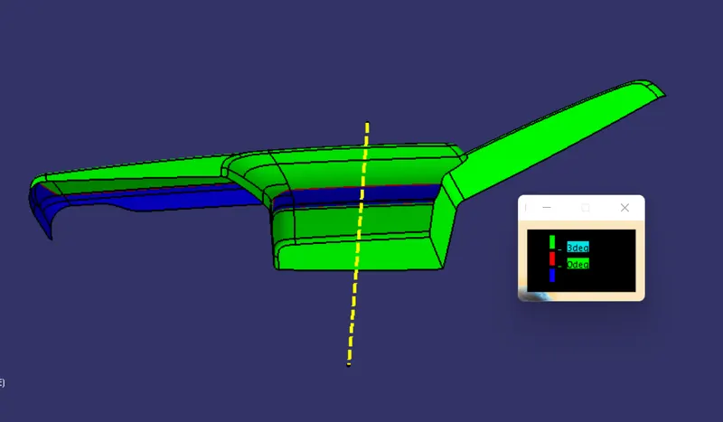
DRAFT ANALYSIS OF CLASS A SURFACE: The draft analysis of the A surface with 3deg is given with the tooling axis. almost all the surface is clearing with 3deg. There are some areas which are not clear so you should be informed to Class A engineer. In this case we will proceed with the same. The image below is the draft analysis of Class A surface.
CREATION OF B SURFACE: The Offset value is given in the master section for B surface. The offset of the A surface at a distance of 2.5mm is the B surface. If there are patches, we can fill them with multi section and extrude and trim method, there are many ways to fill the patches. The image below is B surface.
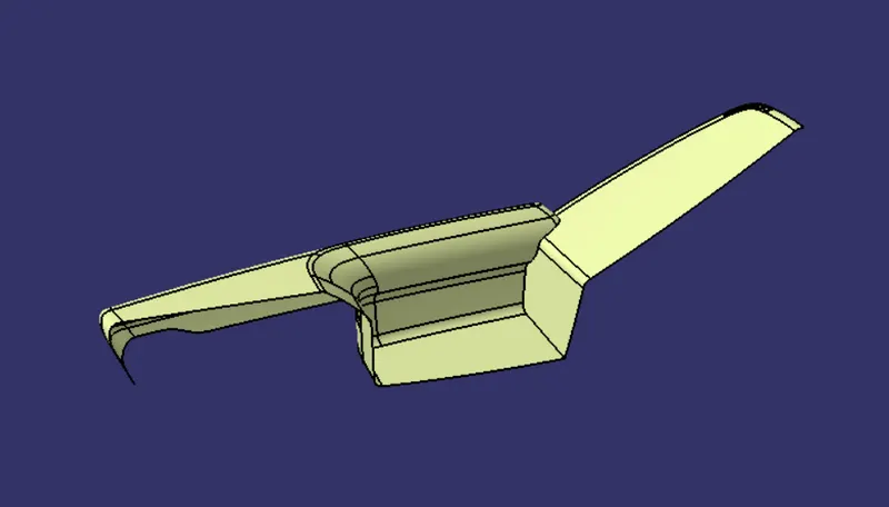
CREATION OF C SURFACE: C surface is the thickness between A and B surface, C surface can be obtained by extracting the A surface edges, and with the help of sweep command C surface can be created. There are many sub commands in sweep, I used them with reference to surface and with draft direction according to the requirement.
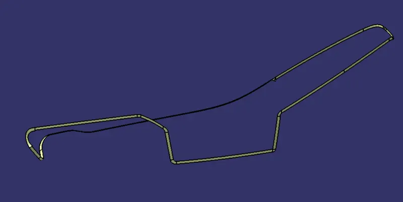
FINAL TRIM: Final trim is the trim of B and C surface by which we can join B and C surface together. and after that joining A surface with B+C surface by this we get A+B+C surface (final product). The image below is the A+B+C Surface. After creation of this surface we have to check whether the surface is closed or no by giving boundary to the surface.
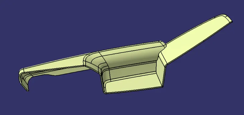
CLOSED SURFACE: Closed surface is the solid body of the surface. In Part workbench there is a command called closed surface by this command we can obtain Closed surface.
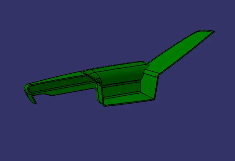
CREATION OF SIDE CORE AXIS: Side core axis is for flanges, create perpendicular line with main tooling axis that is Side core axis.
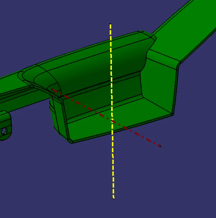
B SIDE FEATURES: As per the Master section we can find that there are flanges with heat stakes holes in it. and there is a block with a heat stake. There are many methods for creation of flanges with master section. i have created the flanges by extracting the master section and giving guide curve and pad it with given thickness. the B side features should be created such a way that the part should not move in any direction. And using design rules give the draft and fillets. The image below is the door arm rest with flanges.
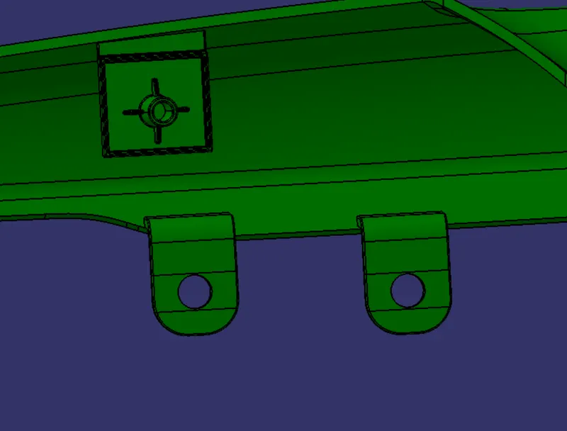
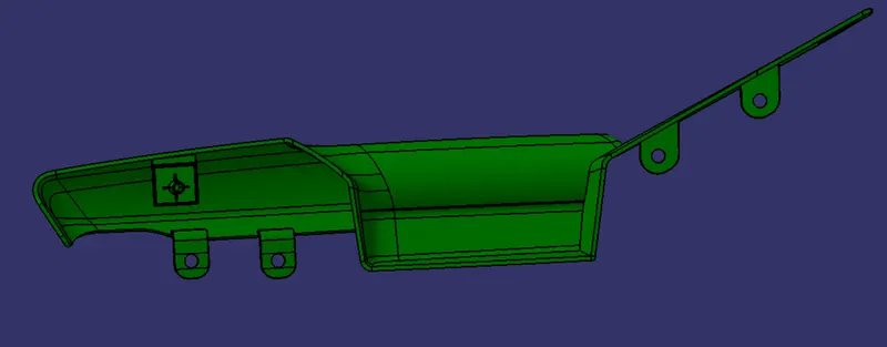
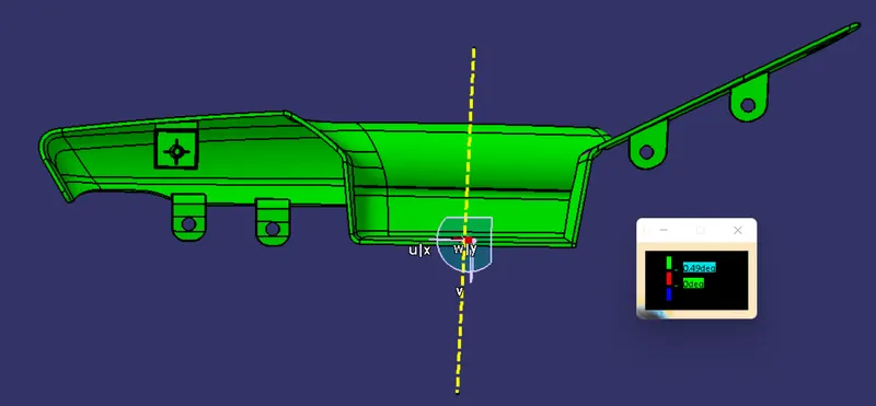
DRAFT ANALYSIS OF THE DOOR ARM REST WITH MAIN TOOLING AXIS:
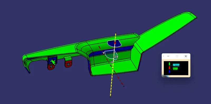
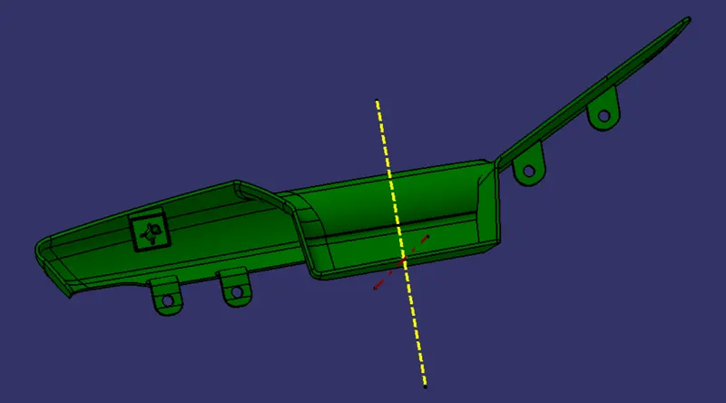
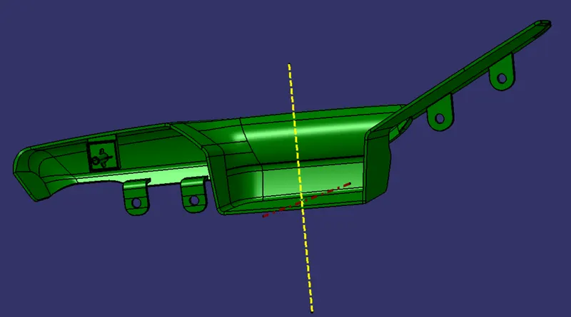
THE COMPLETE PART:
DOOR LOWER SUBSTRATE:
CLASS A SURFACE: First check the given surface with boundary. The given surface is smooth and good to work on.
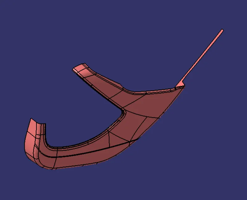
CREATION OF TOOLING AXIS: Take the intersection of A surface, the create two lines in intersection, by bisecting method create a line that is tooling axis.
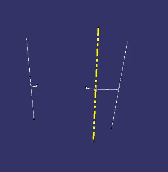
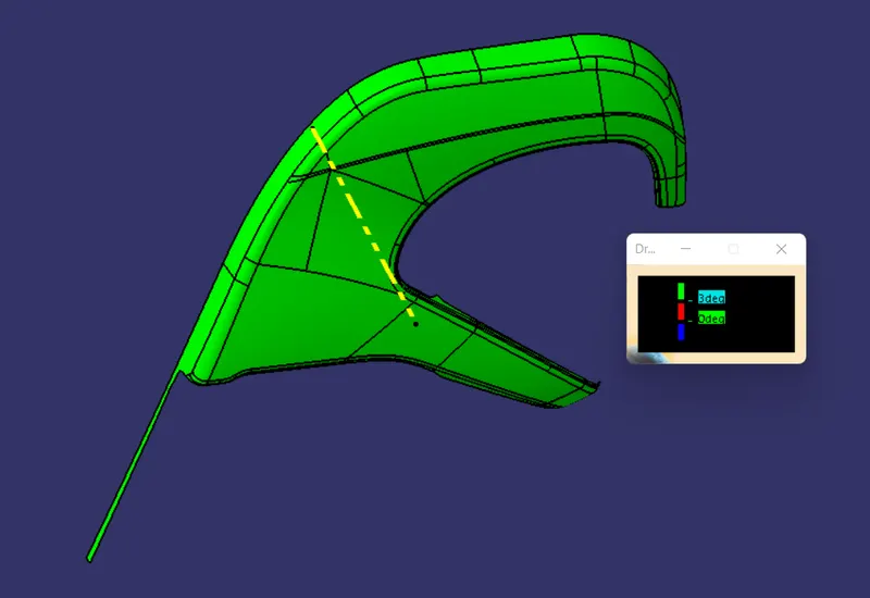
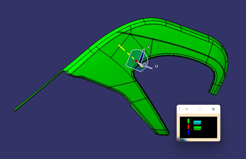
DRAFT ANALYSIS OF CLASS A SURFACE: The draft analysis of the class A surface with 3deg is clearing fully.
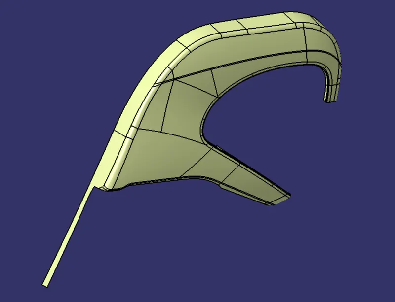
CREATION OF B SURFACE: The offset of the A surface with given distance is B surface. While offsetting the B surface there are some patches that will be filled with multi section.
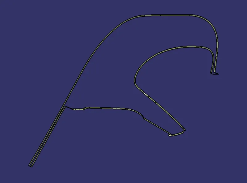
CREATION OF C SURFACE: C surface is the surface between the A and B surface, by extracting the A surface edges and using sweep command the C surface is created, according to the requirement we can use with reference surface and with draft direction command.
FINAL TRIM: Trimming the B and C surface we get B+C surface as one. and joining it with A surface we will get A+B+C surface (final product).
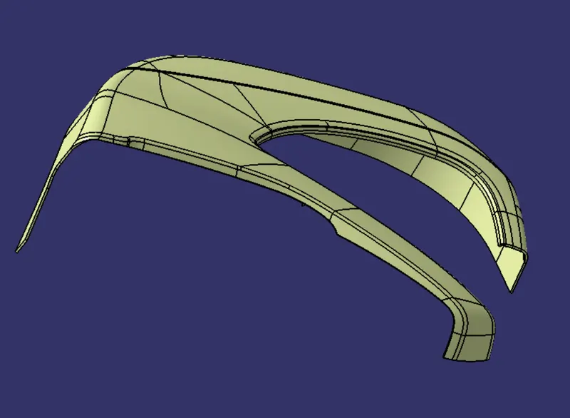
CLOSED SURAFCE: In part workbench there is a command called close surface. by using that command make a solid body of A+B+C surface.
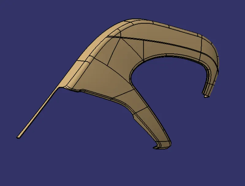
B SIDE FEATURES: For door lower substrate the heat stakes and Dog house can be created.
Heat stakes: Heat stakes are the engineering feature which is fitted in the flange and the top is welded. And according to the design rules it is drafted with 0.5deg and fillet is given. for support ribs can be given at the bottom.
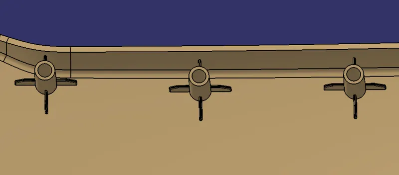
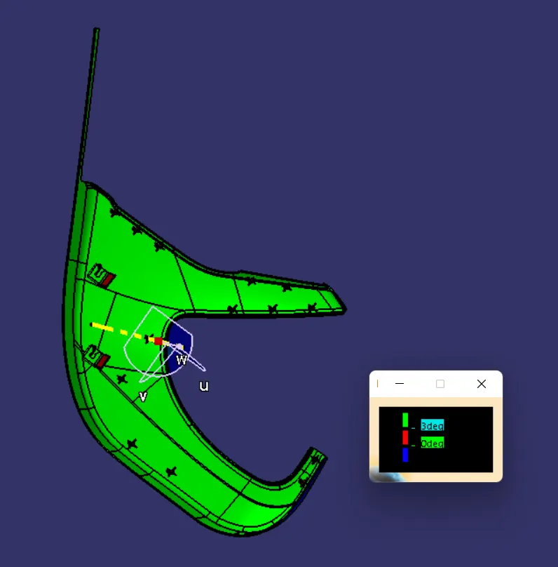
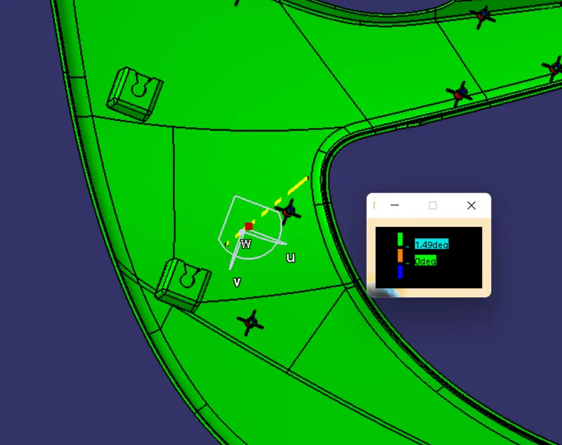
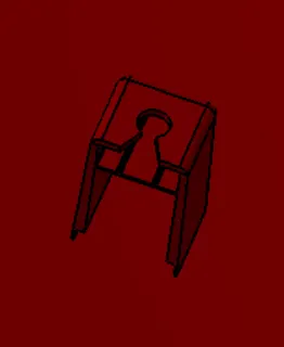
Dog House: According to the requirement the weight and height of the dog house can be decided. and it is created with design rules outside draft is 1.5deg and inside draft is 0.5deg. Later the push pin is assembled in the Dog house.
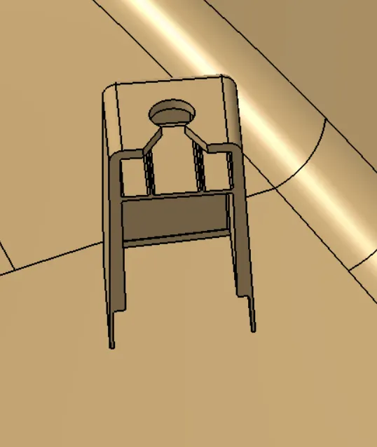
Complete Part:
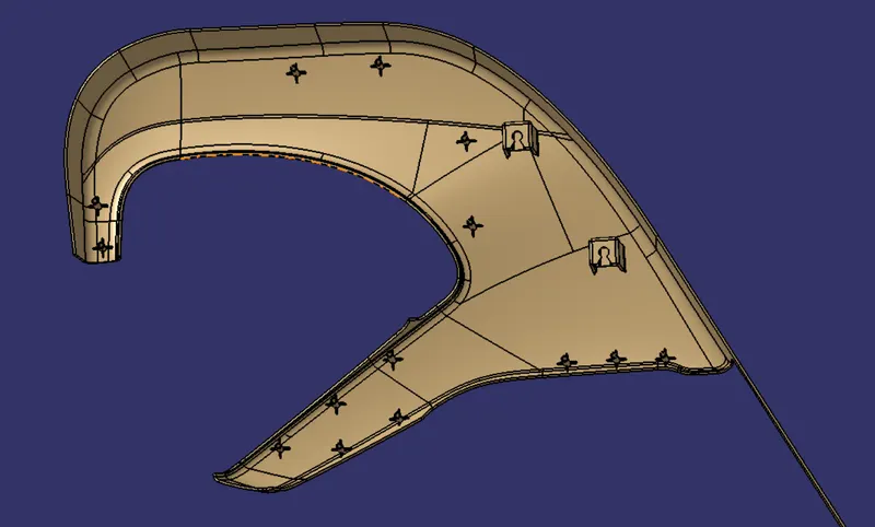
DRAFT ANALYSIS OF THE DOOR LOWER SUBSTRATE:
DRAFT ANALYSIS FROM A SIDE WITH MAIN TOOLING AXIS:
DRAFT ANALYSIS FROM B SIDE WITH MAIN TOOLING AXIS:
DRAFT ANALYSIS FOR DOG HOUSE:
DRAFT ANALYSIS FOR HEAT STAKES WITH MAIN TOOLING AXIS:
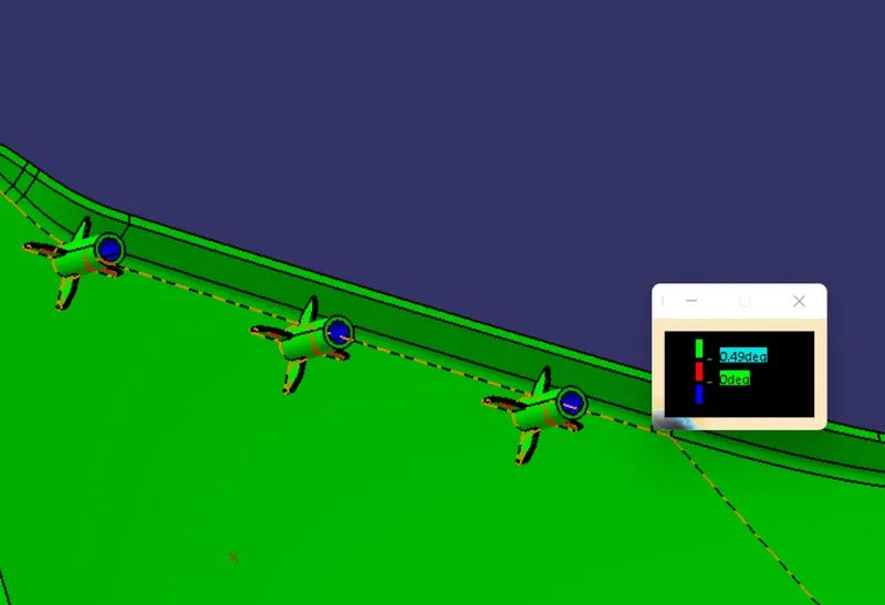
DRAFT ANALYSIS OF DOG HOUSE WITH LIFTER AXIS:
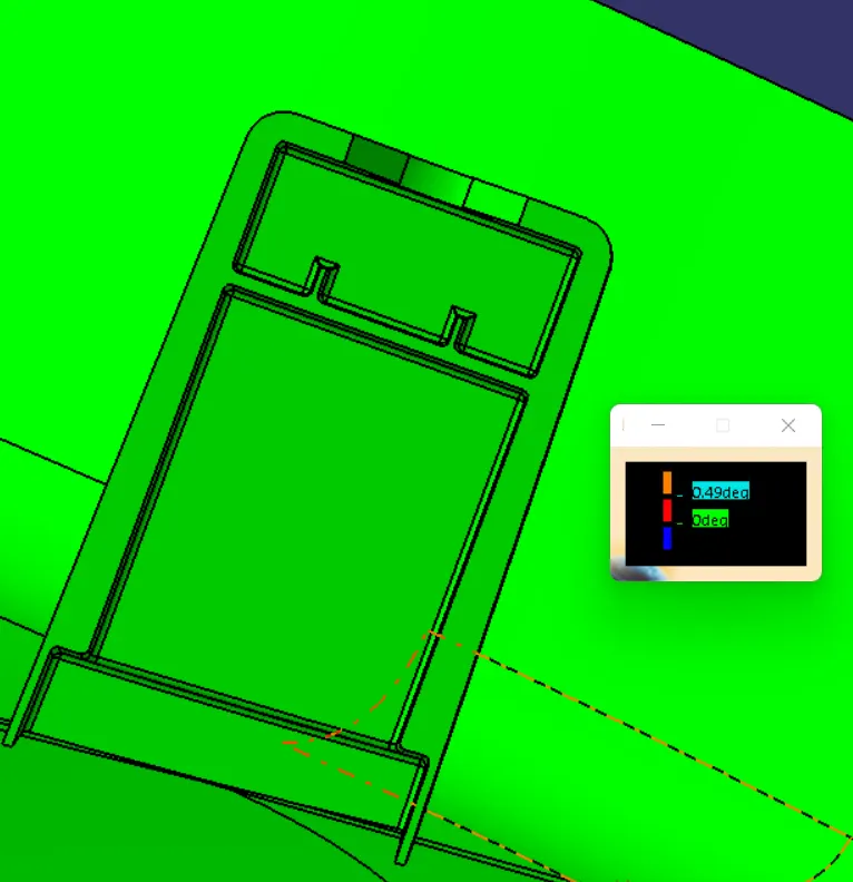
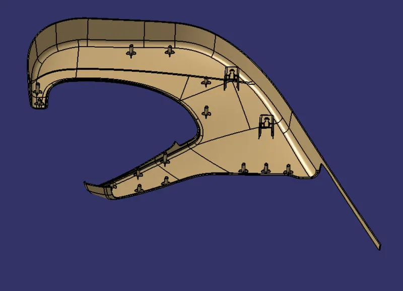
WHOLE PART:
MAP POCKET:
CLASS A SURFACE: A surface is checked with the boundary if there is any patch it will show 2 boundary's.
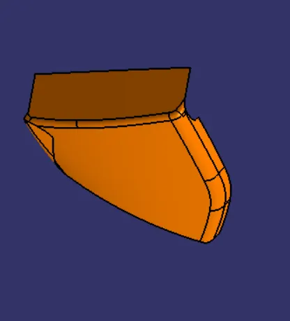
CREATION OF TOOLING AXIS: Take the intersection of A surface, the create two lines in intersection, by bisecting method create a line that is tooling axis.
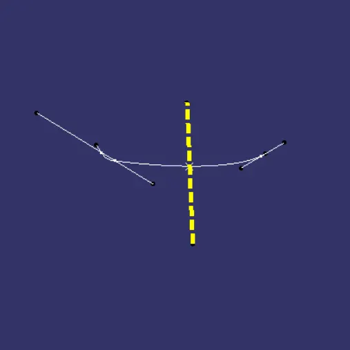
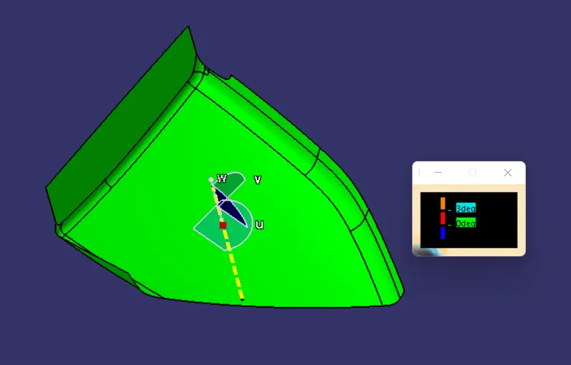
DRAFT ANALYSIS OF A SURFACE: The draft analysis of the class A surface with 3deg is clearing fully.
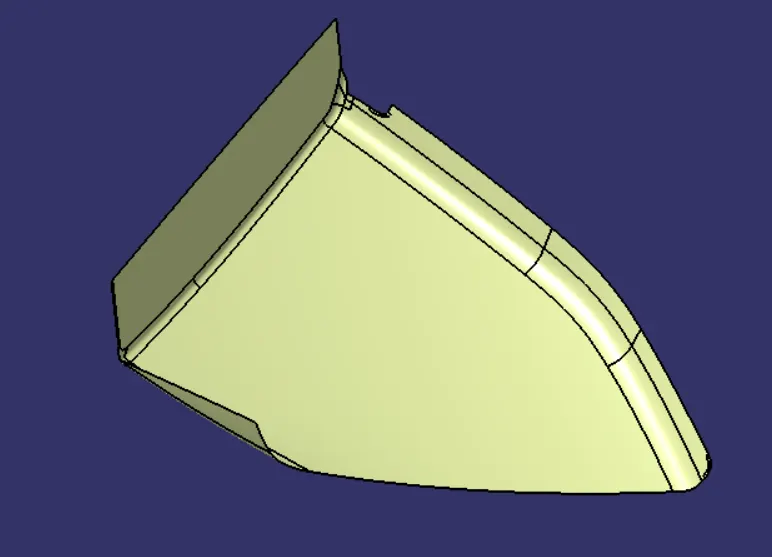
CRATION OF B SURFACE: The offset of the A surface with given distance is B surface. While offsetting the B surface there are some patches that will be filled with multi section.
CREATION OF C SURFACE: C surface is the surface between the A and B surface, by extracting the A surface edges and using sweep command the C surface is created, according to the requirement we can use with reference surface and with draft direction command.
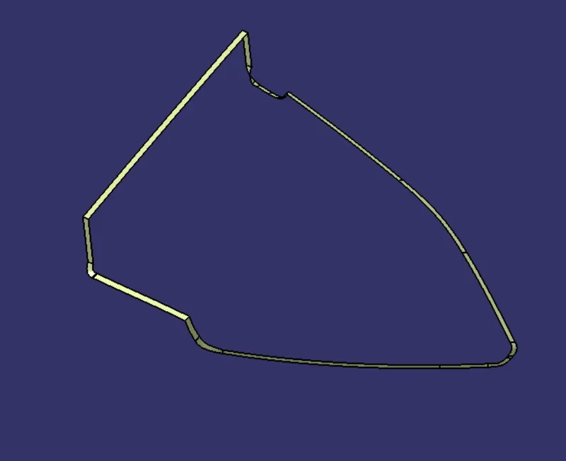
FINAL TRIM: Trimming the B and C surface we get B+C surface as one. and joining it with A surface we will get A+B+C surface (final product).
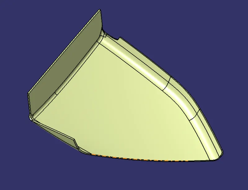
CLOSED BODY: In part workbench there is a command called close surface. by using that command make a solid body of A+B+C surface.
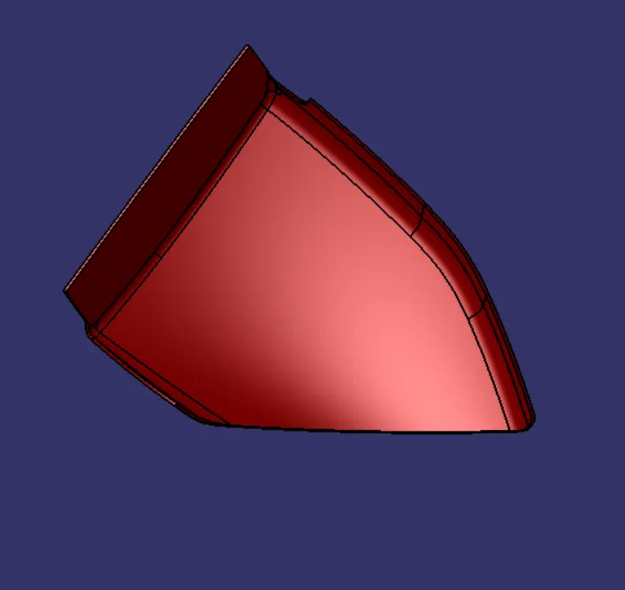
FLANGES: As per the Master section we can find that there are flanges . There are many methods for creation of flanges with master section. i have created the flanges by extracting the master section and giving guide curve and pad it with given thickness. the B side features should be created such a way that the part should not move in any direction. And using design rules give the draft and fillets. The image below is the map pocket with flanges.
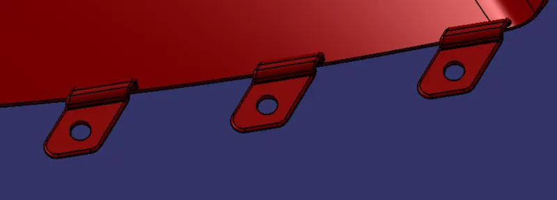
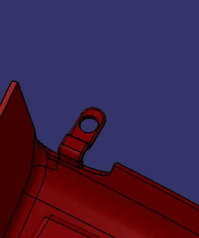
HEAT STAKES: Heat stakes are the engineering feature which is fitted in the flange and the top is welded. And according to the design rules it is drafted with 0.5deg and fillet is given. for support ribs can be given at the bottom.
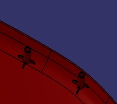
DOG HOUSE: According to the requirement the weight and height of the dog house can be decided. and it is created with design rules outside draft is 1.5deg and inside draft is 0.5deg. Later the push pin is assembled in the Dog house.
DRAFT ANALYSIS WITH MAIN AXIS:
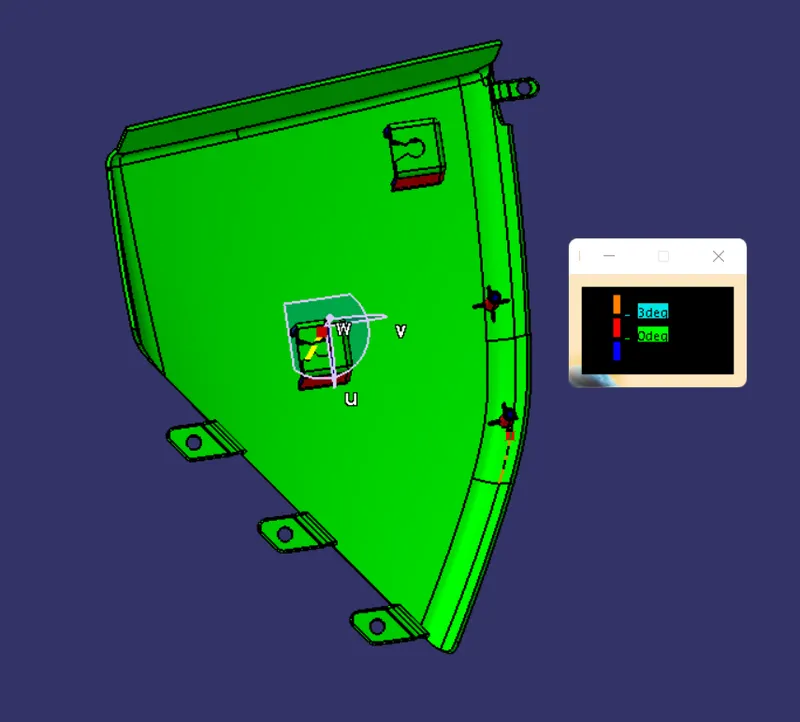
DRAFT ANALYSIS FOE DOG HOUSE OUTER:
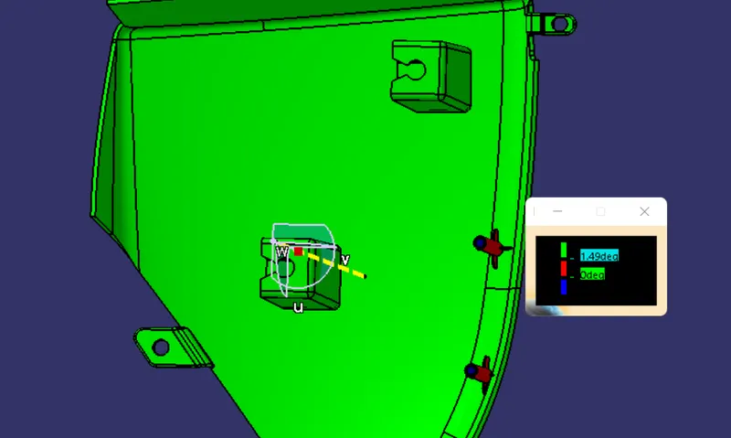
DRAFT ANALYSIS OF HEAT STAKES:
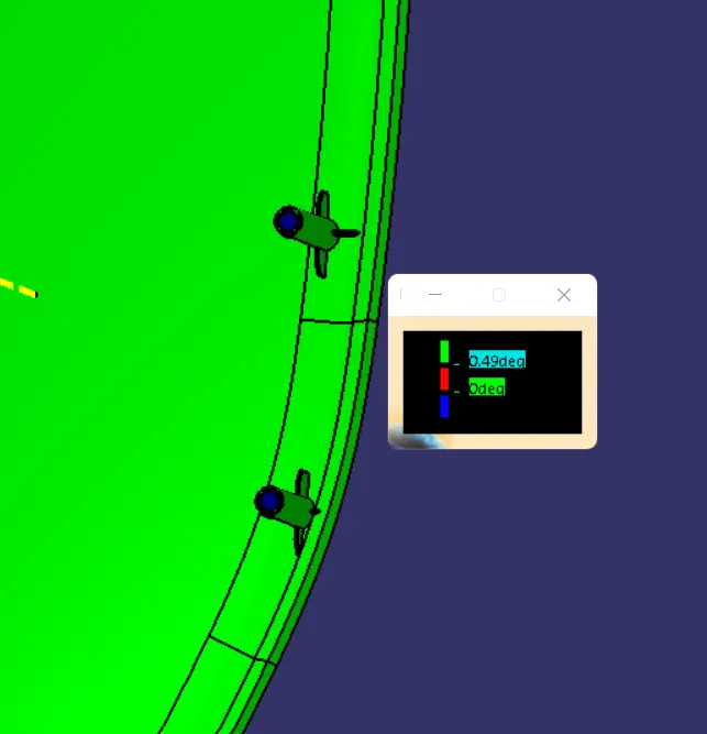
DRAFT ANALYSIS WITH LIFTER AXIS FOR DOG HOUSE INNER:
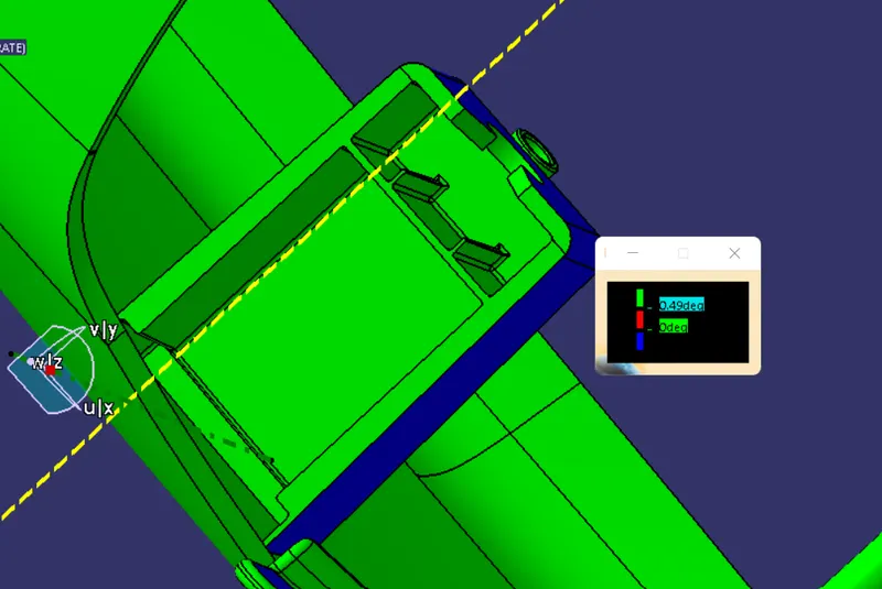
BOTTLE HOLDER
CLASS A: A surface is checked with the boundary if there is any patch it will show 2 boundaries.
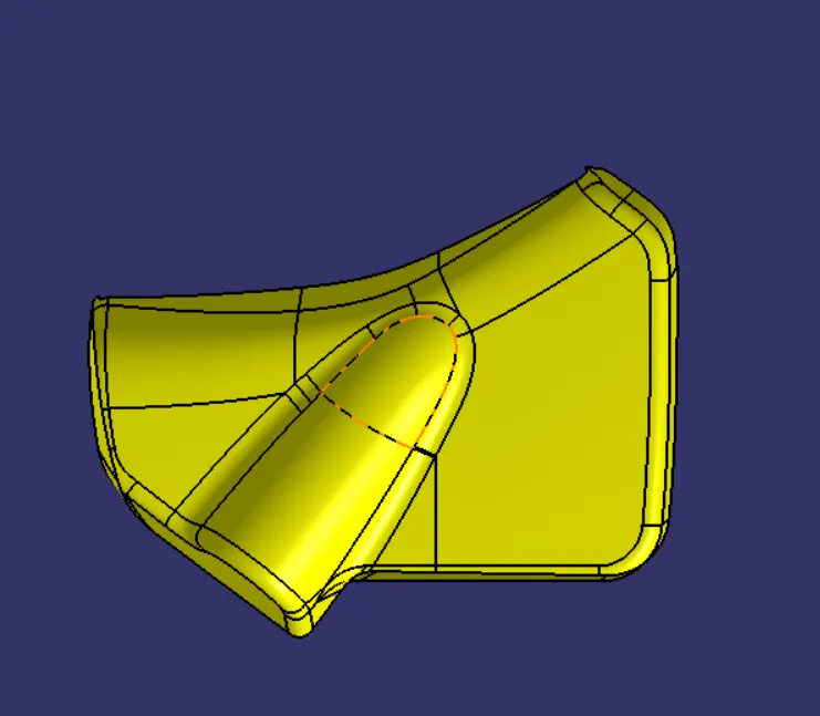
CREATION OF TOOLING AXIS: Take the intersection of A surface, the create two lines in intersection, by bisecting method create a line that is tooling axis.
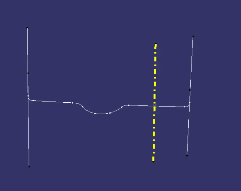
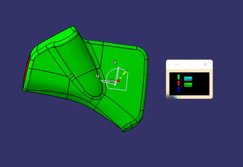
DRAFT ANALYSIS OF CLASS A SURFACE: The draft analysis of the A surface with 3deg is given with the tooling axis. almost all the surface is clearing with 3deg. There are some areas which are not clear so you should be informed to Class A engineer. In this case we will proceed with the same. The image below is the draft analysis of Class A surface.
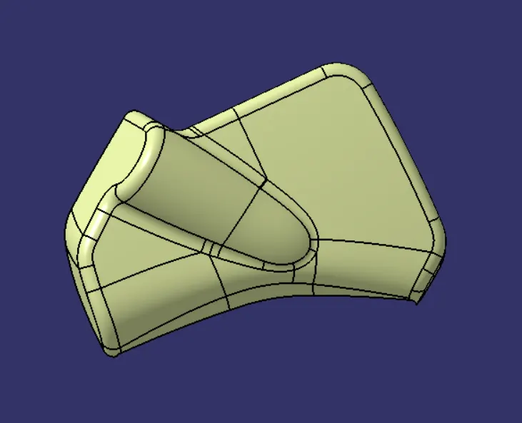
CREATION OF B SURFACE: The Offset value is given in the master section for B surface. The offset of the A surface at a distance of 2.5mm is the B surface. If there are patches, we can fill them with multi section and extrude and trim method, there are many ways to fill the patches. The image below is B surface.
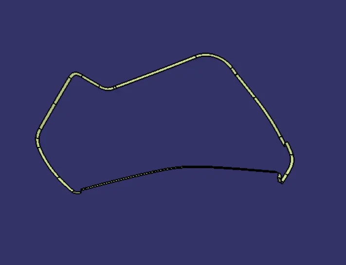
CREATION OF C SURFACE: C surface is the surface between the A and B surface, by extracting the A surface edges and using sweep command the C surface is created, according to the requirement we can use with reference surface and with draft direction command.
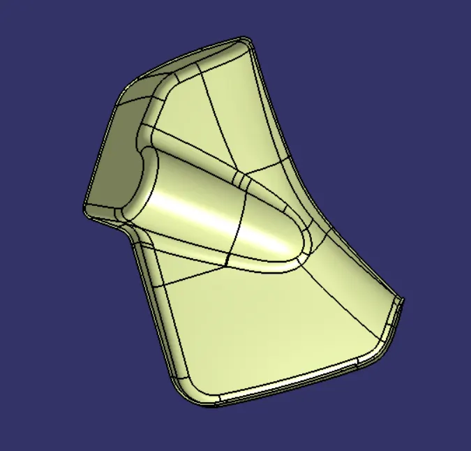
FINAL TRIM: Final trim is the trim of B and C surface by which we can join B and C surface together. and after that joining A surface with B+C surface by this we get A+B+C surface (final product). The image below is the A+B+C Surface. After creation of this surface we have to check whether the surface is closed or no by giving boundary to the surface.
CLOSED BODY: In part workbench there is a command called close surface. by using that command make a solid body of A+B+C surface.
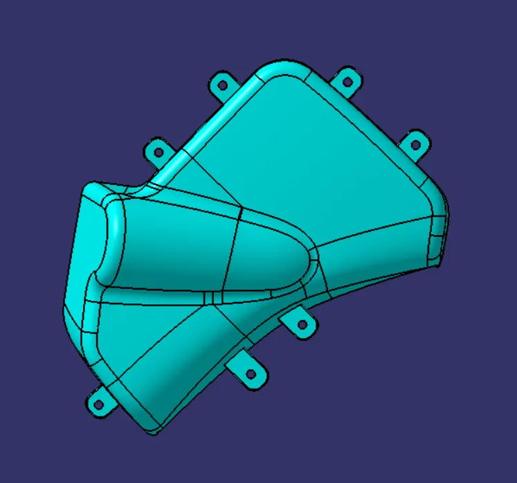
FLANGES: There are many methods for creation of flanges section i have created flanges bysketch and then pad it with thick. the B side features should be created such a way that the part should not move in any direction. And using design rules give the draft and fillets. The image below is the map pocket with flanges.
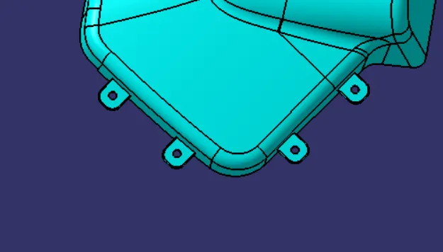
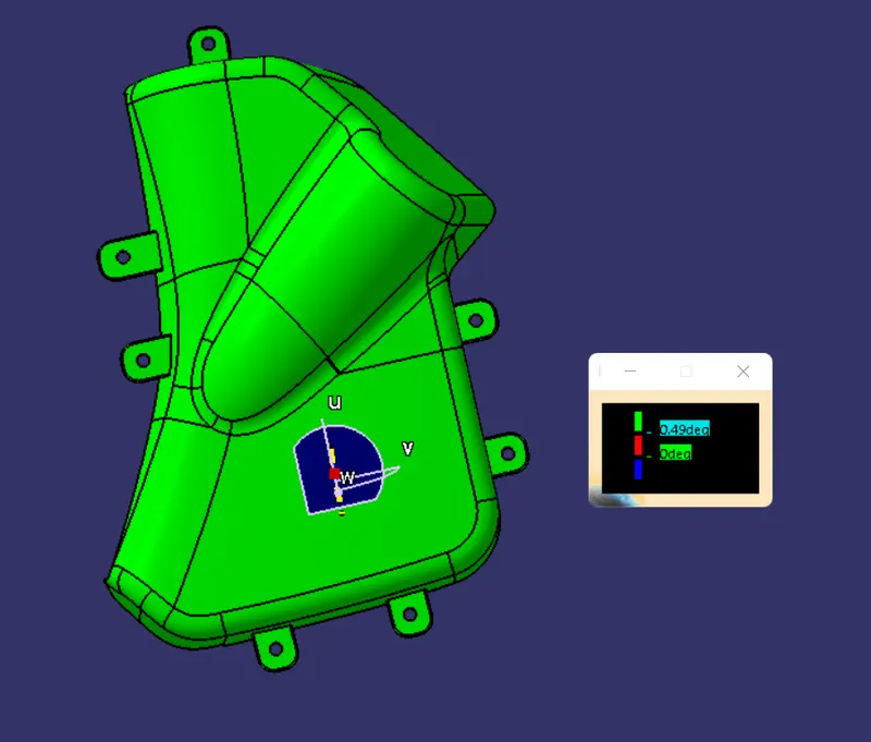
DRAFT ANALYSIS OF FLANGES:
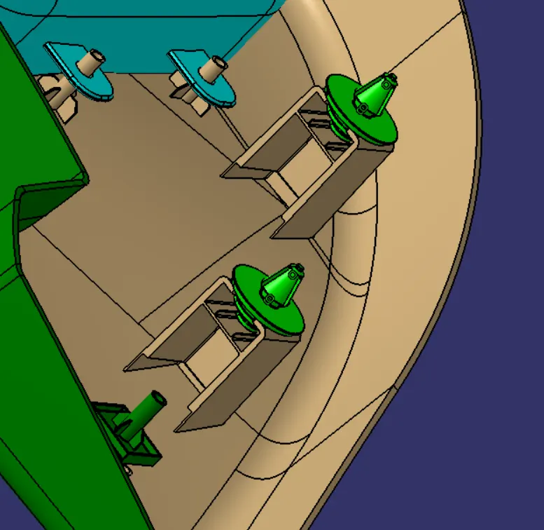
ASSMEBLY OF PUSH PIN IN DOG HOUSE: In assembly workbench first constraint it with the help of axis of both the circular holes. then constraint it with both the surfaces.
ASSEMBLY OF DOOR TRIM PANEL: