Week 11 - Final project
AIM:
To design and develop the vehicle interior door trim using Catia v5 Tool using give A Class Surface and Adding thickness to it. Also to create Ribs and Locators as per the given Master section.
SUMMARY:
This Project explains, in brief, the Design life cycle followed in the automotive industry by working on Practical Model car interior door trim which is a Car interior trim Part. In this report, we have explained the steps followed to create a solid body of the Door Trim Panel taking Class A Surface as Input and Creating a Tooling axis and B surface with respect to the Class A Surface and Creation of Class C Surface and also the Draft Analysis. The attachment features also designed and reported as per the given master section considering all the design rules for the creation of ribs and doghouse.
OVERVIEW OF DESIGN LIFE CYCLE:
Why plastics in Automobile:
In earlier days most of the automobile parts are in metal. After some years plastic parts are introduced in automobiles, it is cheaper than metal, it reduced the weight of automobiles for that efficiency increased. In modern-day cars, most of the interior parts are plastics front & rear bumpers are in plastics it causes reduces the weight & cost of the vehicle. and Plastic parts make it more stylish and looking good.
Research:
The research design refers to the overall strategy that you choose to integrate the different components of the study in a coherent and logical way, thereby, ensuring you will effectively address the research problem; it constitutes the blueprint for the collection, measurement, and analysis of data.
Design Requirements:
The design requirements for a product are based on the wants and needs of the intended customer. These wants and needs must be identified by the company making the product, and they are often communicated by the target customer in nontechnical and sometimes vague terms.
Feasibility:
In some cases, a feasibility study is carried out after which schedules, resource plans, and estimates for the next phase are developed. The feasibility study is an evaluation and analysis of the potential of a proposed project to support the process of decision-making. It outlines and analyses alternatives or methods of achieving the desired outcome. The feasibility study helps to narrow the scope of the project to identify the best scenario. A feasibility report is generated following which Post Feasibility Review is performed.
Concept Generation:
A concept study is often a phase of project planning that includes producing ideas and taking into account the pros and cons of implementing those ideas. This stage of a project is done to minimize the likelihood of error, manage costs, and evaluate the potential success of the intended project. In any event, once an engineering issue or problem is defined, potential solutions must be identified. These solutions can be found by using idea the mental process by which ideas are generated. It can be done normally by Clay Modelling.
Preliminary /Class A Surface Design:
The preliminary design or high-level design includes often bridges a gap between design conception and detailed design, particularly in cases where the level of conceptualization achieved during the idea is not sufficient for a full evaluation. So in this task, the overall system configuration is defined, and schematics, diagrams, and layouts of the project may provide early project configuration. During detailed design and optimization, the parameters of the part being created will change, but the preliminary design focuses on creating the general framework to build the project on. This is also Called CLASS A SURFACE DESIGN. Styling or A class surface are the terms used in plastic product design. That means the surface of a component is smooth (aesthetic) or visible side to the human eye after the part is assembled.
Design of Interior Door trim:
Interior Door trim consists of 6 major components that are
- Lower Substrate
- Bottle Holder
- Map Pocket
- Door Arm Rest split part
- Coin holder with armrest
- Upper Substrate
In this Model, we are designing only Lower Substrate, Map pocket, Bottle Holder, Coin holder with armrest, Door armrest, and Attachment features like a dog house and Heat stakes and doing draft analysis for all the components.
Detailed Design:
This may consist of procurement of materials as well. This phase further elaborates on each aspect of the project/product by complete description through solid modeling, drawings as well as specifications. Computer-Aided Design (CAD) programs have made the detailed design phase more efficient. For example, a CAD program can provide optimization to reduce volume without hindering a part's quality. It can also calculate stress and displacement using the finite element method to determine stresses throughout the part. This involves the Creation of Tooling Axis, Class B, and Class C Surface Creation with respect to the Class A Surface and also Considering the Draft angle. The Design Engineer role is prominent in this stage.
Design Engineers will study the input Class A Surface and Master sections which are developed by the preliminary design team and the procedure followed in the creation of the Door trim are as below:
Class A Surface
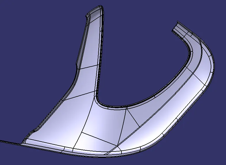
In the Automotive industry, there will be a dedicated team who will perform the aesthetic designing of various components including the whole vehicle. They will create various concept sketches after the idea. After that, they will also create a Class A surface of the product. This class A surface is then passed over to the NPD CAD team. They will initially inspect the Class A surface in order to check if the design is the manufacture or if it is following the engineering principles. If there are any issues with the design, they will contact the product design team and will ask to modify the Class A surface in order to solve the problem. Here I received the Class-A surface as shown below.
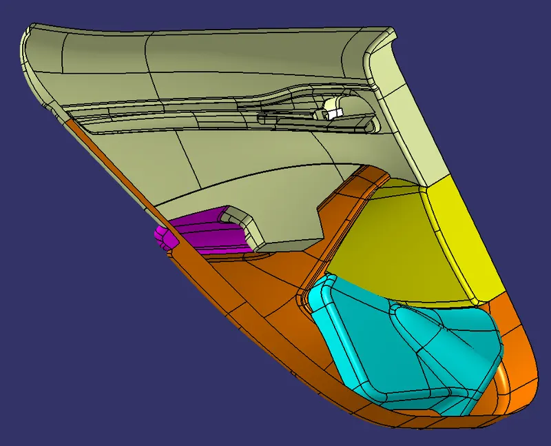
we created a lower substrate portion only that part is shown below.
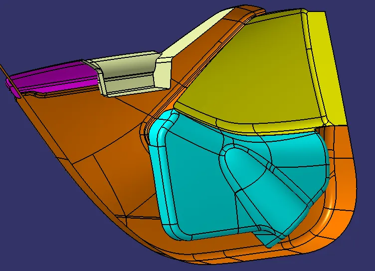
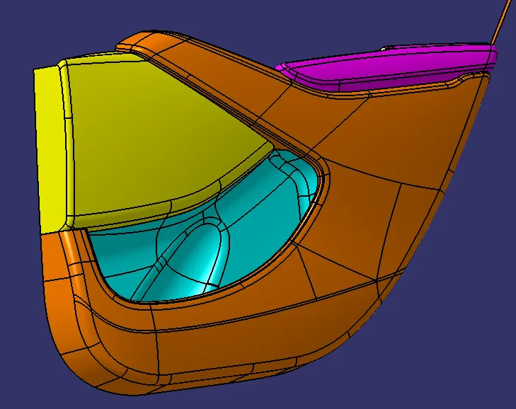
- Designing of lower Substrate
Creation of Tooling Axis:
The tooling axis is nothing but the direction in which the Core and Cavity Opens and Closes. The Design Engineer works are to Analyse the Class A Surface and find out the best possible tooling direction keeping in mind all the draft angle is with respect to the tooling axis so that the Component can be easily ejected from the mold.
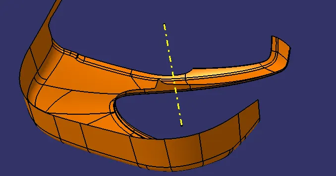
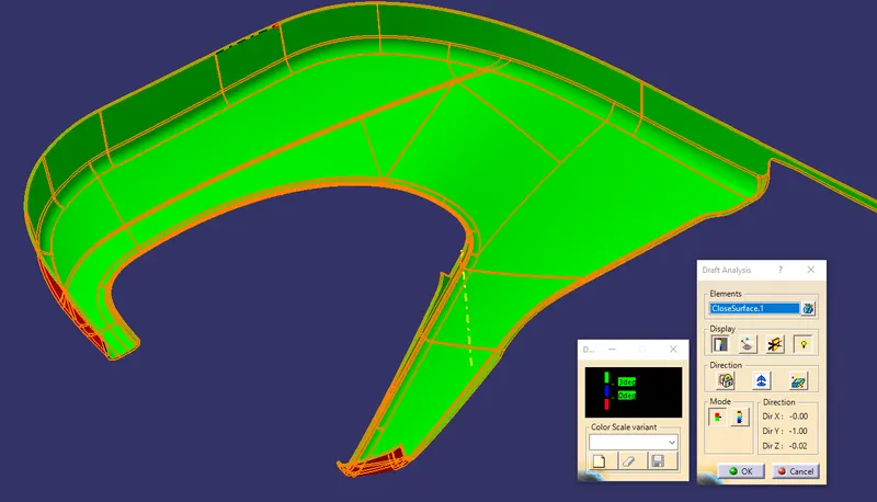
Draft Analysis:
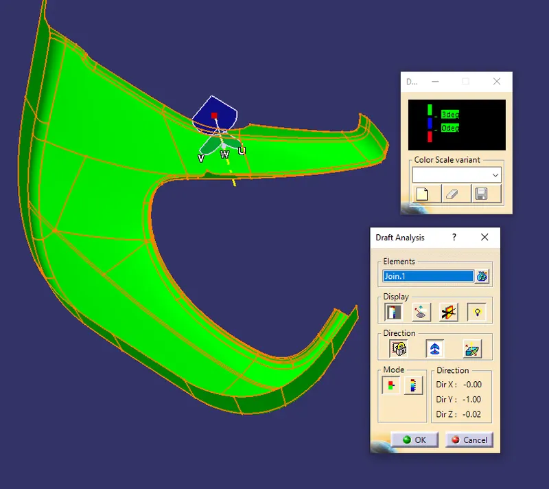
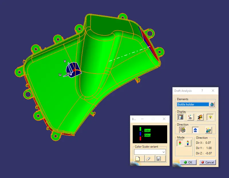
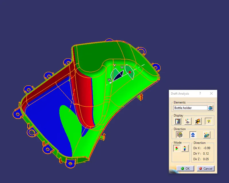
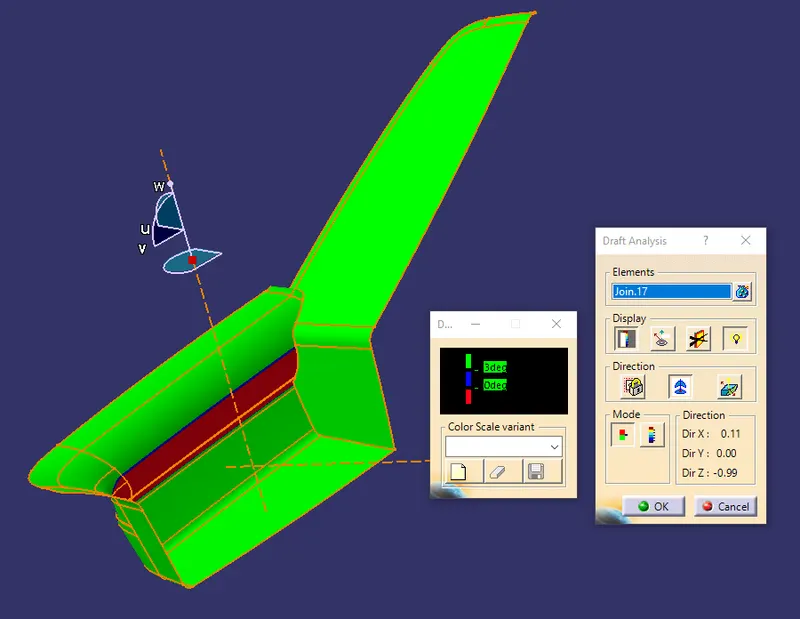
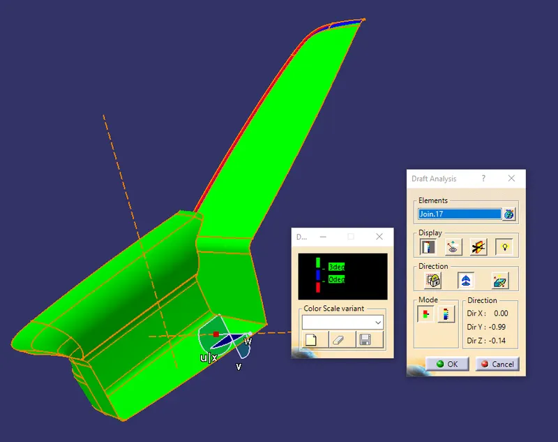
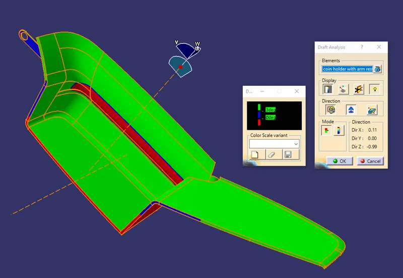
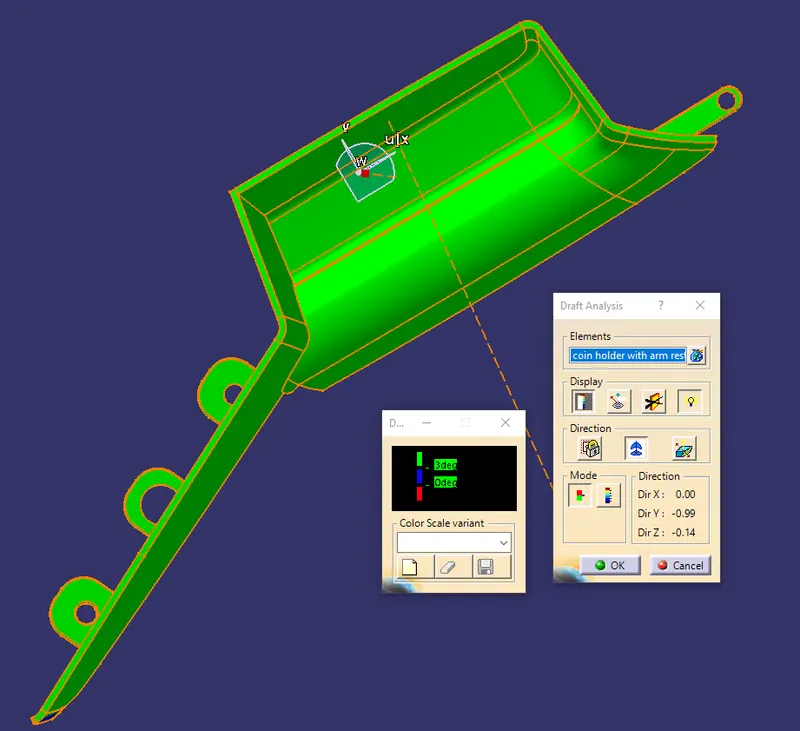
Parts Cannot be ejected from the tool if it is at a 90-degree surface. for that reason, A small Draft angle is to provide for each and every surface of the Component in order to easily remove components from the mold without any defects. The draft is the angle at which the part is tapered to allow it to release. Most of the parts require a minimum of 0.5 degrees to 1 degree however 3 degrees are widely accepted in plastic component design. Draft Analysis is the technique used to analyze whether our designed product is manufacture with required conditions or not. The color codings are shown in an image it depends on the angle we set on the color scale variant green is shown above the 3-degree draft angle. the blue color showed in between 0 to 3 degrees angle. The red color showed a negative angle.
Class B Surface Creation:
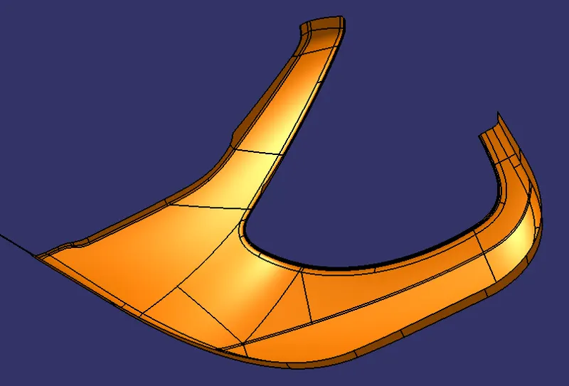
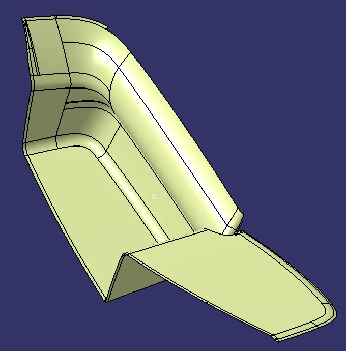
Once after getting the tooling axis we need to create the B Surface which is Parallel to the Class A Surface at the distance of the thickness of the component. It also includes the Each and Every edge, Fillets, a feature which is there in Class A Surface. In the Door Trim, the B Surface is at a proportionate distance of 2.5mm from the Class A Surface.
Class C Surface Creation:
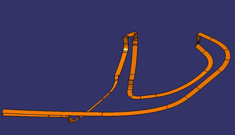
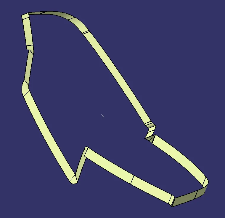
Class C Surface is Swept along the boundary of Class A at an angle perpendicular to the CLASS A Surface with respect to the Tooling Axis Direction with a Nominal Draft angle of 3 degrees.
Combining CLASS A, B, and C Surfaces to get Closed Surfaces:
Once after Creating the Class B and Class C, First Join the Class A and Class C Surface together with a Connexity of Surface less than 0.003mm and The Surfaces are Merged. Merged Surfaces are then to be trimmed with Class b Surfaces to get a Closed surface.
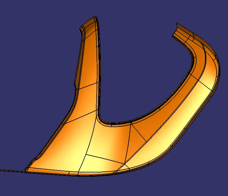
Once done with the generative sheet design, Switch to Part design and Converted to the Closed Surface into the Closed Volume.
DRAFT ANALYSIS
Main tooling axis:-
. Designing of Bottle Holder
Creation of Tooling Axis:
Created the tooling axis of the bottle holder as per the drafting analysis all sides are cleared while molding. create the point on the surface by that point-created line using point and direction. create an axis system on that point that gives y-axis direction as an existing line. Using that axis and line created another line and adjust the angle of the line where it clear the draft analysis.
Creation of sliding Tooling Axis:
Some of the parts did not clear in a single tooling axis we created another sliding tooling axis. For clearing that uncleared portion. In the tool, they provide a separate slider for this portion. That slider movement axis will be created that axis is called the sliding tooling axis.
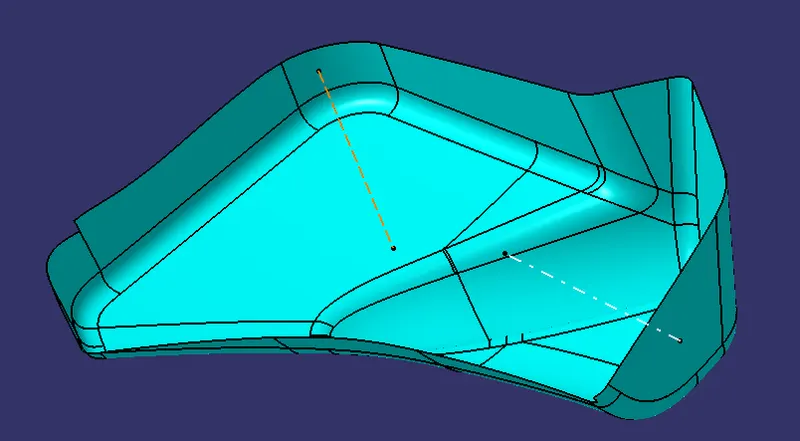
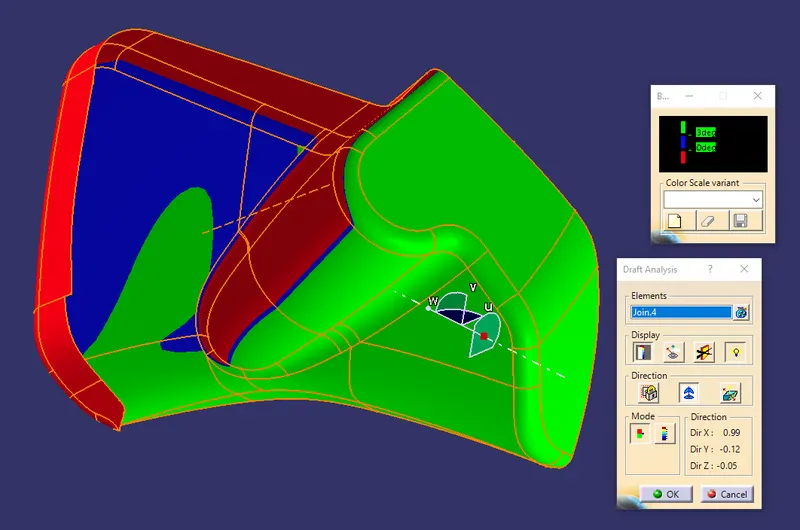
Draft Analysis:
Parts Cannot be ejected from the tool if it is at a 90-degree surface. for that reason, A small Draft angle is to provide for each and every surface of the bottle holder. For that purpose create the tooling axis and analyze whether our product is ok or not.
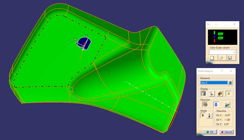
Class B Surface Creation:
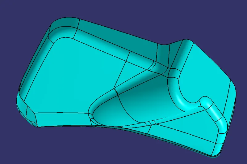
Once after getting the tooling axis we need to create the B Surface which is Parallel to the Class A Surface at the distance of the thickness of the component. It also includes the Each and Every edge, Fillets, a feature which is there in Class A Surface. In the Door Trim, the B Surface is at a proportionate distance of 2.5mm from the Class A Surface.
Class C Surface Creation:
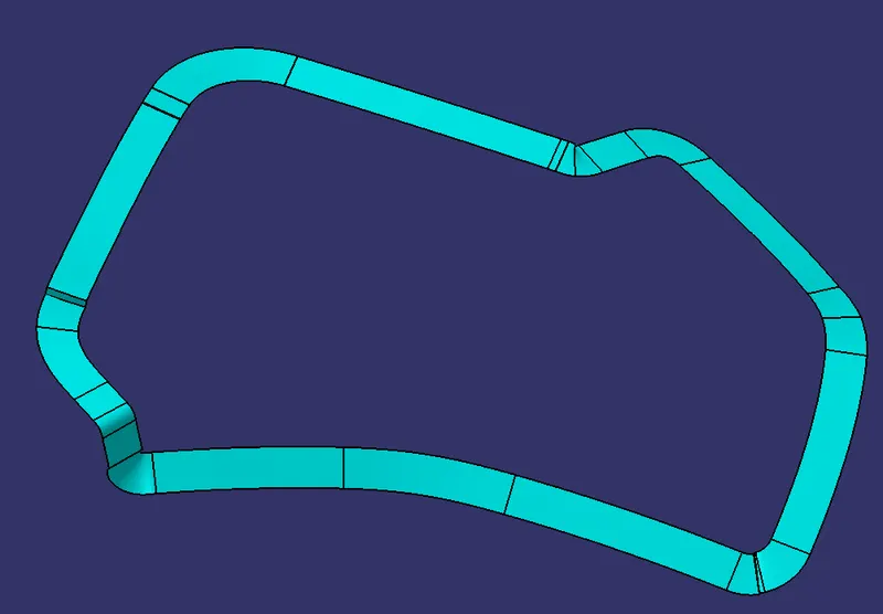
Class C Surface is Swept along the boundary of Class A at an angle perpendicular to the CLASS A Surface with respect to the Tooling Axis Direction with a Nominal Draft angle of 3 degrees.
Combining CLASS A, B, and C Surfaces to get Closed Surfaces:
Once after Creating the Class B and Class C, First Join the Class A and Class C Surface together with a Connexity of Surface less than 0.003mm and The Surfaces are Merged. Merged Surfaces are then to be trimmed with Class b Surfaces to get a Closed surface.
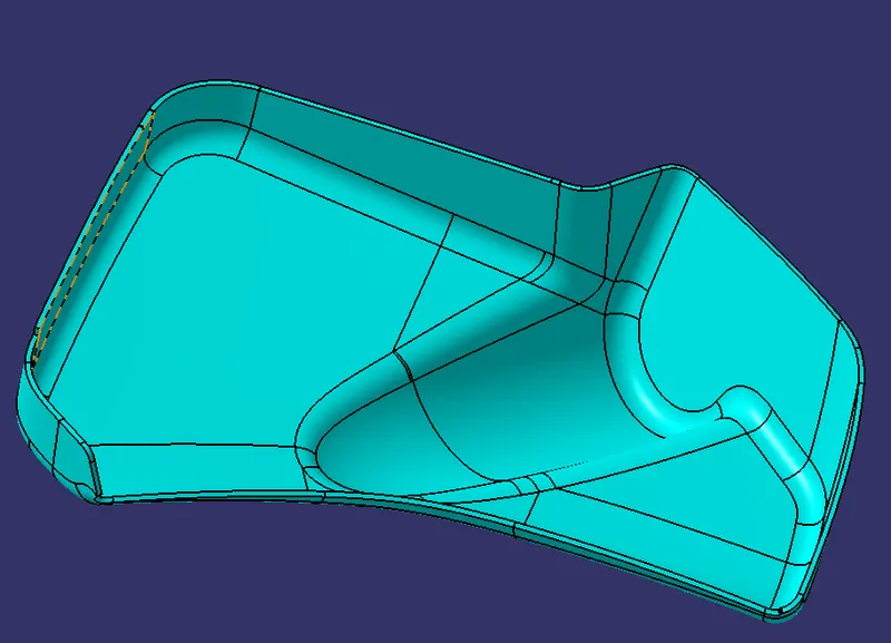
Once done with the generative sheet design, Switch to Part design and Converted to the Closed Surface into the Closed Volume.
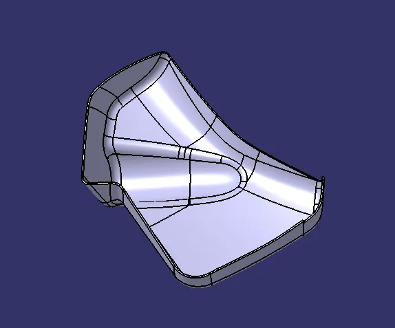
DRAFT ANALYSIS FOR BOTTLE HOLDER
Main tooling axis:-
Sliding tooling axis:-
. Designing of Map Pocket
Creation of Tooling Axis:
Created the tooling axis of the bottle holder as per the drafting analysis all sides are cleared while molding. create the point on the surface by that point-created line using point and direction. create an axis system on that point that gives y-axis direction as an existing line. Using that axis and line created another line and adjust the angle of the line where it clear the draft analysis.
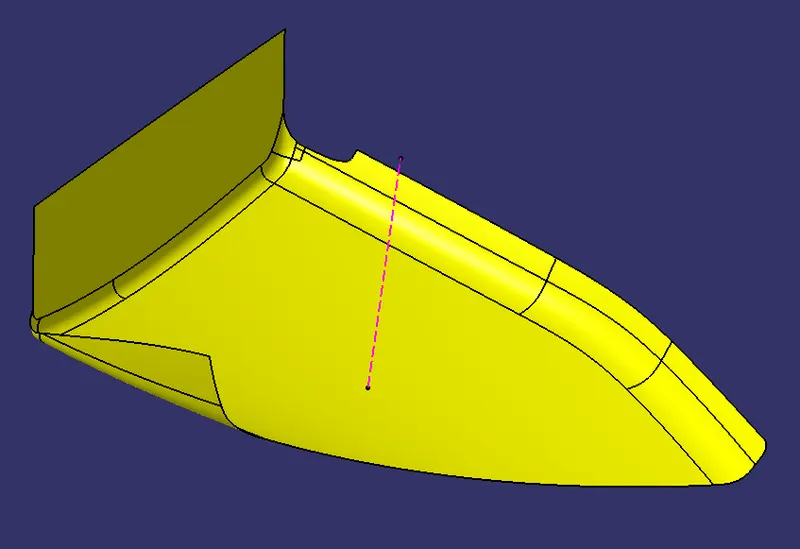
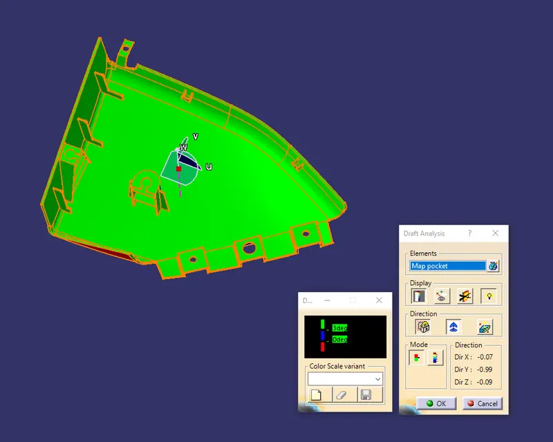
Draft Analysis:
Parts Cannot be ejected from the tool if it is at a 90-degree surface. for that reason, A small Draft angle is to provide for each and every surface of the bottle holder. For that purpose create the tooling axis and analyze whether our product is ok or not.
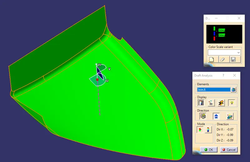
Class B Surface Creation:
Once after getting the tooling axis we need to create the B Surface which is Parallel to the Class A Surface at the distance of the thickness of the component. It also includes the Each and Every edge, Fillets, a feature which is there in Class A Surface. In the Door Trim, the B Surface is at a proportionate distance of 2.5mm from the Class A Surface.
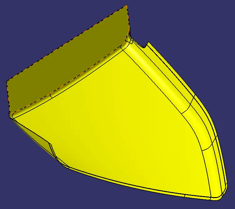
Class C Surface Creation:
Class C Surface is Swept along the boundary of Class A at an angle perpendicular to the CLASS A Surface with respect to the Tooling Axis Direction with a Nominal Draft angle of 3 degrees.
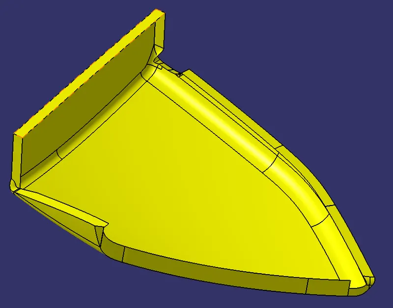
Combining CLASS A, B, and C Surfaces to get Closed Surfaces:
Once after Creating the Class B and Class C, First Join the Class A and Class C Surface together with a Connexity of Surface less than 0.003mm and The Surfaces are Merged. Merged Surfaces are then to be trimmed with Class b Surfaces to get a Closed surface.
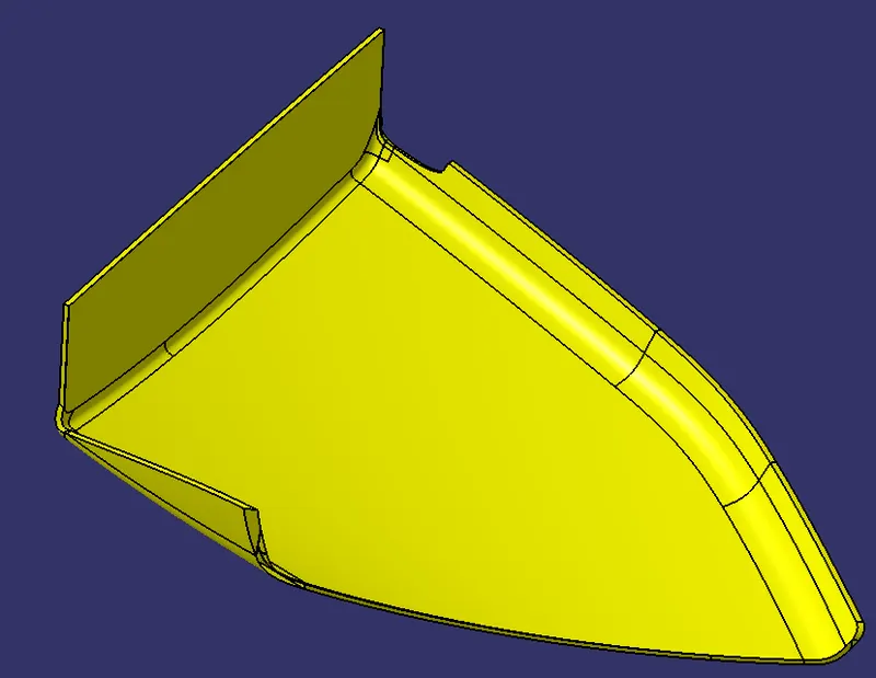
Once done with the generative sheet design, Switch to Part design and Converted to the Closed Surface into the Closed Volume.
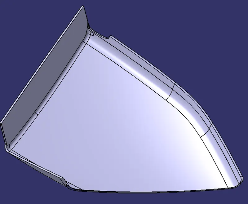
DRAFT ANALYSIS FOR MAP POCKET
Main tooling axis:-
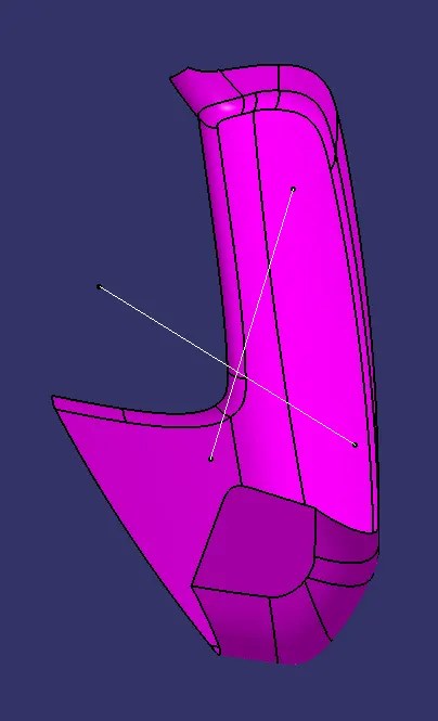
. Designing of armrest split part
Creation of Tooling Axis:
Created the tooling axis of the bottle holder as per the drafting analysis all sides are cleared while molding. create the point on the surface by that point-created line using point and direction. create an axis system on that point that gives y-axis direction as an existing line. Using that axis and line created another line and adjust the angle of the line where it clear the draft analysis. if the part did not clear in a single tooling axis we created another sliding tooling axis.
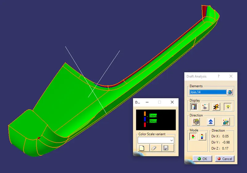
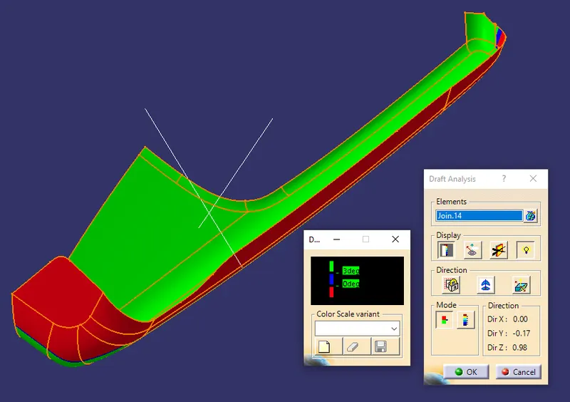
Draft Analysis:
Parts Cannot be ejected from the tool if it is at a 90-degree surface. for that reason, A small Draft angle is to provide for each and every surface of the bottle holder. For that purpose create the tooling axis and analyze whether our product is ok or not.
Class B Surface Creation:
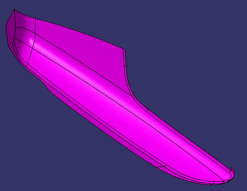
Once after getting the tooling axis we need to create the B Surface which is Parallel to the Class A Surface at the distance of the thickness of the component. It also includes the Each and Every edge, Fillets, a feature which is there in Class A Surface. In the Door Trim, the B Surface is at a proportionate distance of 2.5mm from the Class A Surface.
Class C Surface Creation:
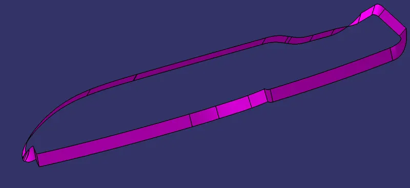
Class C Surface is Swept along the boundary of Class A at an angle perpendicular to the CLASS A Surface with respect to the Tooling Axis Direction with a Nominal Draft angle of 3 degrees.
Combining CLASS A, B, and C Surfaces to get Closed Surfaces:
Once after Creating the Class B and Class C, First Join the Class A and Class C Surface together with a Connexity of Surface less than 0.003mm and The Surfaces are Merged. Merged Surfaces are then to be trimmed with Class b Surfaces to get a Closed surface.
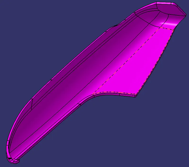
Once done with the generative sheet design, Switch to Part design and Converted to the Closed Surface into the Closed Volume.
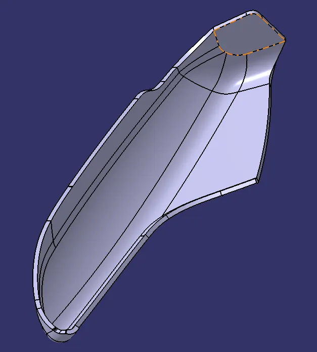
DRAFT ANALYSIS FOR ARMREST SPLIT PART
Main tooling axis:-
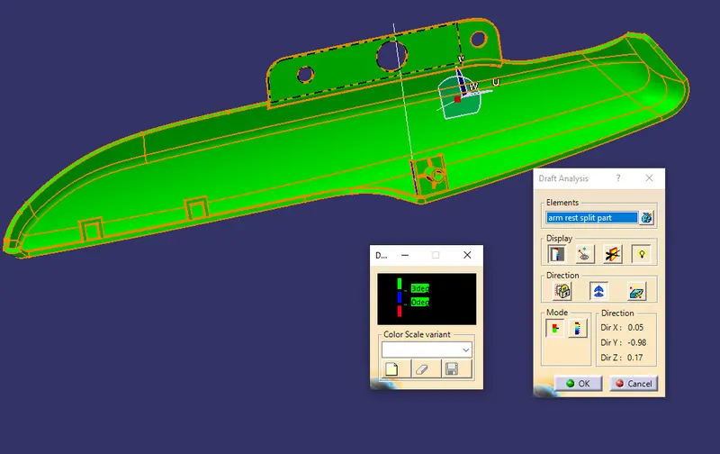
Sliding tooling axis:-
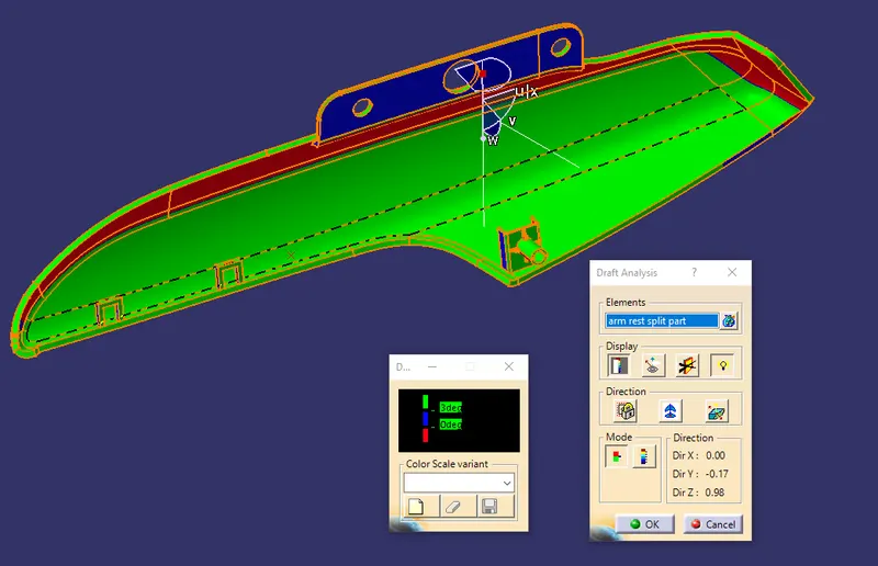
. Designing of coin holder armrest
Creation of Tooling Axis:
Created the tooling axis of the bottle holder as per the drafting analysis all sides are cleared while molding. create the point on the surface by that point-created line using point and direction. create an axis system on that point that gives y-axis direction as an existing line. Using that axis and line created another line and adjust the angle of the line where it clear the draft analysis. if the part did not clear in a single tooling axis we created another sliding tooling axis.
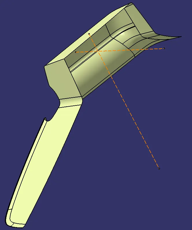
Draft Analysis:
Parts Cannot be ejected from the tool if it is at a 90-degree surface. for that reason, A small Draft angle is to provide for each and every surface of the bottle holder. For that purpose create the tooling axis and analyze whether our product is ok or not.
Class B Surface Creation:
Once after getting the tooling axis we need to create the B Surface which is Parallel to the Class A Surface at the distance of the thickness of the component. It also includes the Each and Every edge, Fillets, a feature which is there in Class A Surface. In the Door Trim, the B Surface is at a proportionate distance of 2.5mm from the Class A Surface.
Class C Surface Creation:
Class C Surface is Swept along the boundary of Class A at an angle perpendicular to the CLASS A Surface with respect to the Tooling Axis Direction with a Nominal Draft angle of 3 degrees.
Combining CLASS A, B, and C Surfaces to get Closed Surfaces:
Once after Creating the Class B and Class C, First Join the Class A and Class C Surface together with a Connexity of Surface less than 0.003mm and The Surfaces are Merged. Merged Surfaces are then to be trimmed with Class b Surfaces to get a Closed surface.
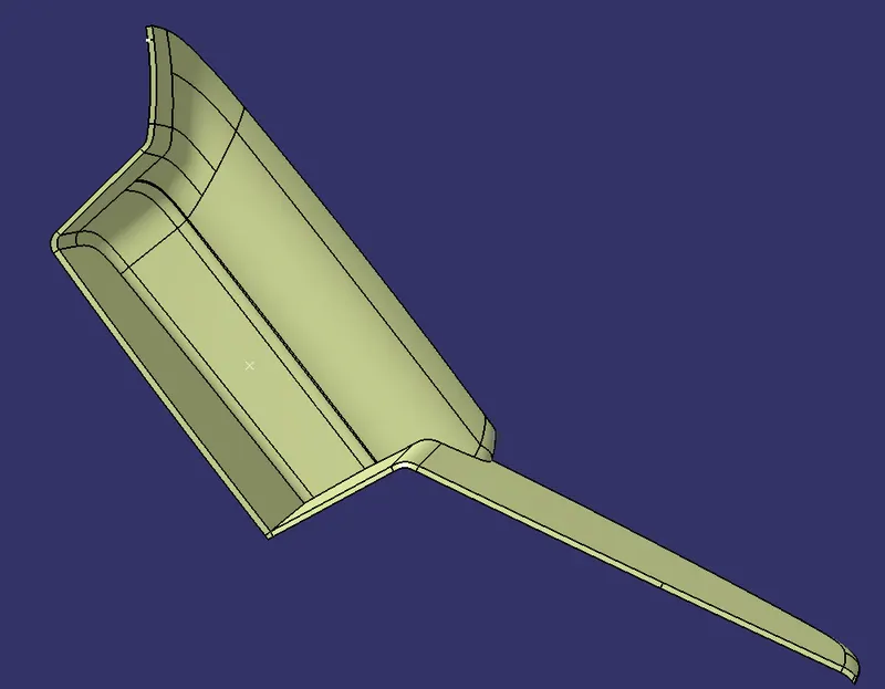
Once done with the generative sheet design, Switch to Part design and Converted to the Closed Surface into the Closed Volume.
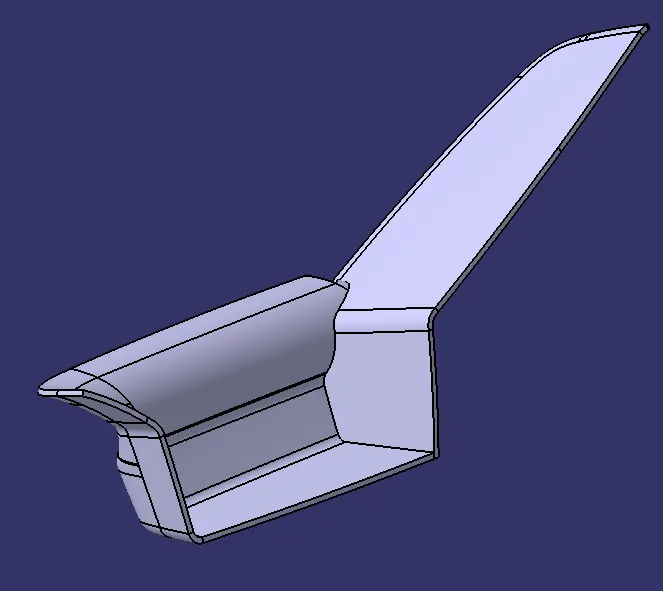
Draft analysis for armrest:
Main tooling axis:-
Slider tooling axis:-
ATTACHMENT FEATURES
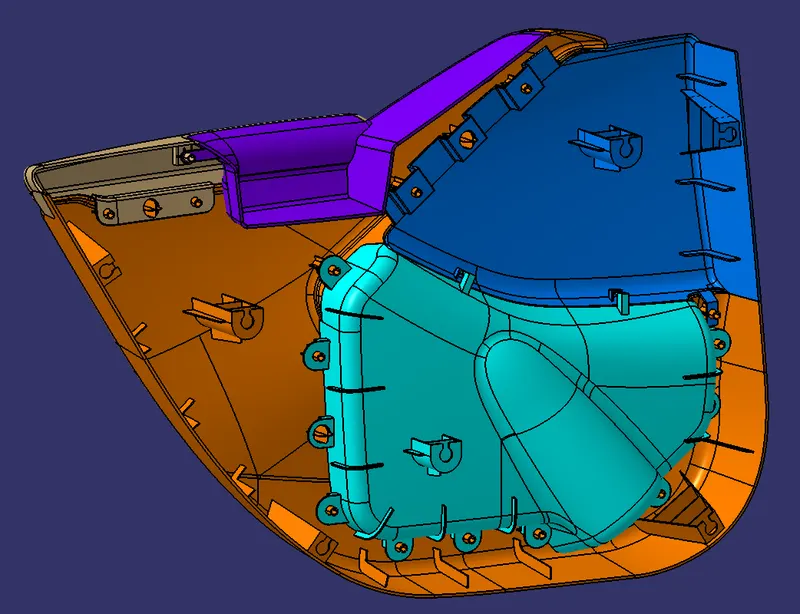
Creation of Ribs and Dog house:
Ribs provide an economical stiffness and strength in molded parts without increasing overall wall thickness. They also facilitate, Locating and arresting the components of an assembly. Providing alignment in mating parts Along with stops and guides for the mechanisms.
GENERAL GUIDELINES FOR dog house:-
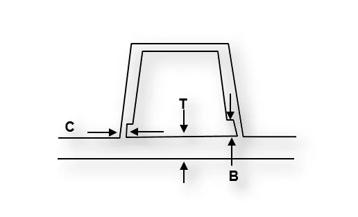
- Doghouse wall thickness at the intersection of the part wall ( C ) should be 40% or less than the main wall stock ( T ).
- Height of ( B ) should be between 3.0 – 6.0 mm
Proper rib design involves 5 main issues:
- Thickness
- Height
- Location
- Quantity
- Manufacturability
Creation of Heat Stakes:
A heat stake feature finds use in many part designs as a point of attachment and assembly. The most common variety consists of cylindrical projections with holes designed for Plastic welding to attach plastic parts to each other. Under service conditions, bosses are often subjected to loading's not encountered in other sections of a component. Provide a generous radius at the base of the boss for strength and ample draft for easy part removal from the mold.
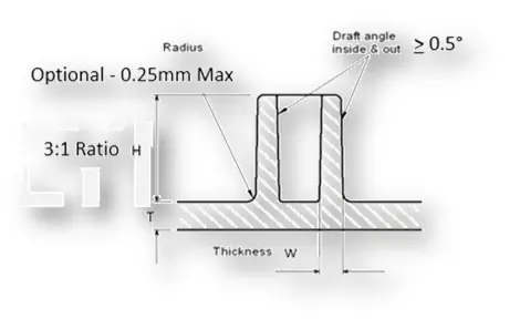
GENERAL GUIDELINES FOR heat stakes:-
Draft - 0.5 degrees on walls of the heat stakes.
Thickness - Typically 40% of the nominal wall at the base.
Height to Diameter Ratio - 3:1
Radii - 0.25mm maximum radii.
Creation of Retainer clip Dog house:
This Retainer clip is used to attach with BIW to Trims for that push clip or Retainer clip we make a provision that could be reached out to BIW from the base of trims. so we make a dog house and make the cut out on the dog house that is called a retainer clip dog house.
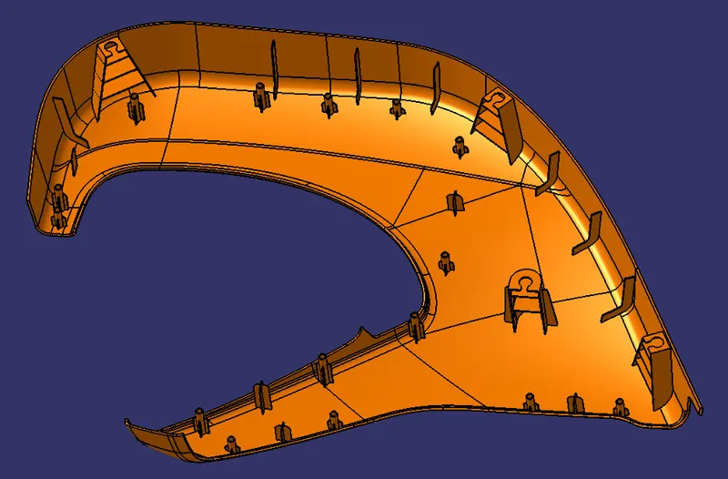
Lower Substrate with Attachment feature:
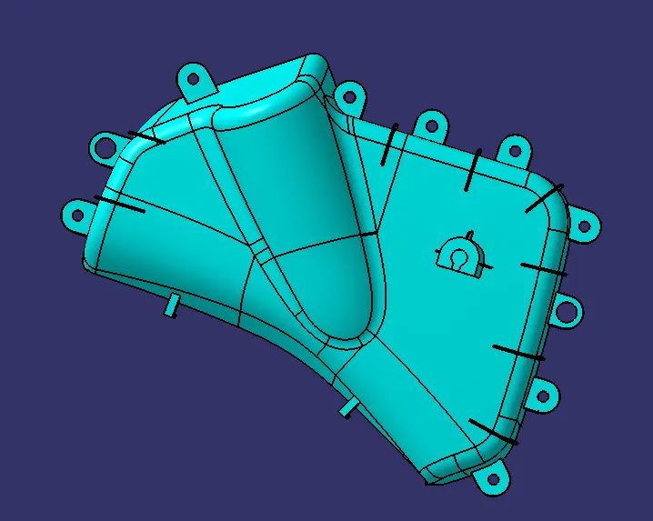
Bottle Holder with attachment feature:
Map Pocket with attachment feature:
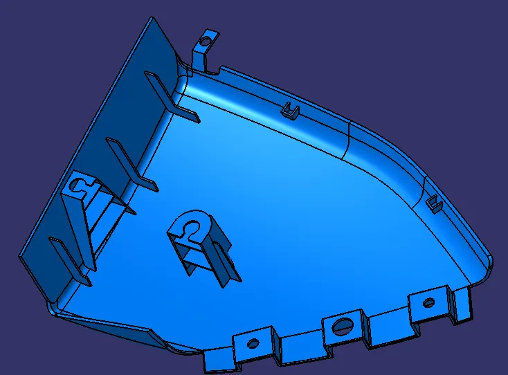
Armrest with attachment feature:
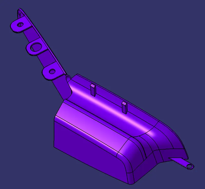
Armrest split part with attachment feature:
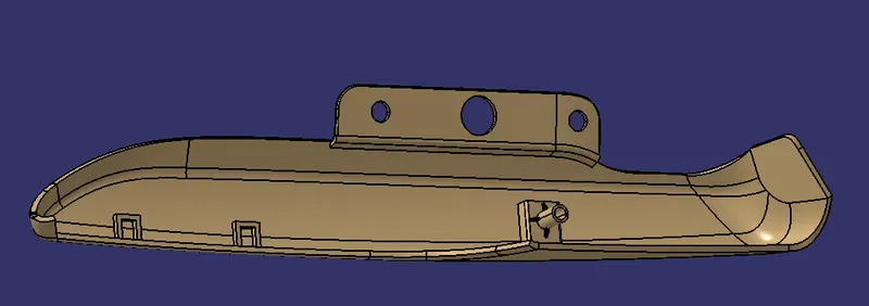
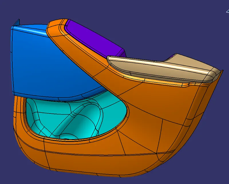
FULL ASSY:
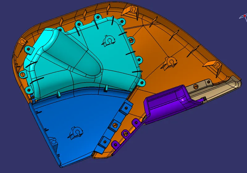
Conclusion:
Thus the Interior trim of the Car interior door trim is designed using the given A Class Surface as the Input and B and C Class Surfaces are created with respect to the Class A Surface. By using the Given Master section attachment features i.e. Ribs and doghouse, flanges and push clips created considering all the design rules for the creation of Ribs and Doghouse. Also carried out the draft analysis to check whether the Component is easily manufacturable or not with the given draft of 3 degrees for the surfaces and 0.5 degrees for the attachment features. With all these data and reports we can conclude that the Draft Analysis is Very important to design any Plastic Component because when we making a part that will be molded, the analysis will verify that all surfaces are favorable for being pulled from a cavity. It may also highlight or give insight into "trouble" areas.