Photo Realistic Rendering
Introduction
In this project I will be demonstrating Full Component modelling & assembly of American chopper in a sequence. The explanation included the components descriptions and How I made it in the Solid Work softwares using Part modelling Workbench.
Objective
The main Objective Of this course module is to learn the basics of part modelling and also exploring most of the tools that are used in designing using solid works.
Design Methodology
Chopper Modelling
⇩
Part modelling Assembling Rendering
⇩ ⇩ ⇩
- Transmission belt 1. Creating mates 1. Appearances
- Kick Stand 2. Lights
- Front Fender 3. Camera
- Rear fender 4. Background
- Chain
- Oil tank
- Pedal
- Front wheel
- Rear wheel
- Front fork
- Chassis
- Engine
- Gas tank
Parts to be modelled for chopper.
The following parts are modelled in Solidworks & assembled together.
- Transmission belt
- Kick Stand
- Front Fender
- Rear fender
- Chain
- Oil tank
- Pedal
- Front wheel
- Rear wheel
- Front fork
- Chassis
- Engine
- Gas tank.
Now we will see each and every part in detail.
1.Transmission Belt.
Transmission belt is used for transferring the power from engine to gearbox.
Features used
- Extrude
- Fillet
- Appearance
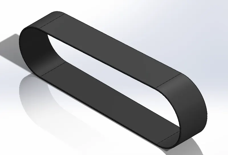
The profile of the transmission belt is created as per the dimensions in the front plane, the belt is given thickness of 3.5 mm. Once the sketch is completed the belt is extruded. The square edges are given fillet. The transmission belt is made out of mate rubber.
- Kick stand:
Kick Stand is a supporting structure provided to a bicycle or motorcycle to help it stand in a vertical position when stationary.
Features used:
- Lofted Boss/Base,
- Dome,
- Extruded Cut,
- Extruded Boss/Base
- Fillet
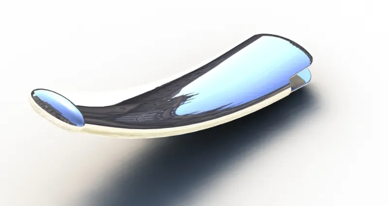
The loft feature is used to create the kick stand. Two ellipses are created on the right plane, one at the top end and another one at the bottom end of the kickstand. A path is sketched on the front plane which joins the center points of the two ellipses created before using a pierce relation between the center of the ellipses and the path. Using a loft, the body of the kickstand is created. Elliptical dome features are used to create the rounded end of the kickstand. A slot with an extruded boss is created at the top end of the stand using which it is connected to the chassis. At last fillets are provided to the sharp edges of the stand. Chrome plate appearance is applied to the kickstand.
- Front Fender
Front fender is the cover for the front wheel. It protects from muds, sands, small stones, etc on the road.
Features used:
- Revolve Boss/Base,
- Split,
- Trim,
- Shell
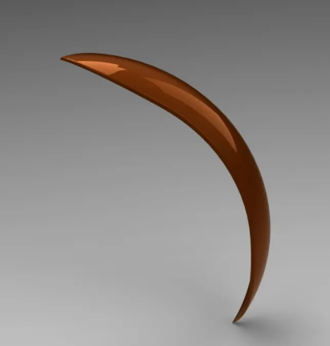
A sketch is created in the front plane using a three point arc and offset it to meet the thickness of the fender. Create an axis at the origin. Using a revolve boss the required front fender is created. Two different sketches are created in the top plane and the right plane to cut the front fender into required shape. Fillets are created on the sharp edges of the fender Desired appearance is applied to the fender.
- Rear Fender:
Rear fender is the semi cover for the rear wheel. It protects from muds, sands, small stones, etc on the road.
Features Used:
- Revolve Boss/Base,
- Fillet,
- Trim,
- Shell.
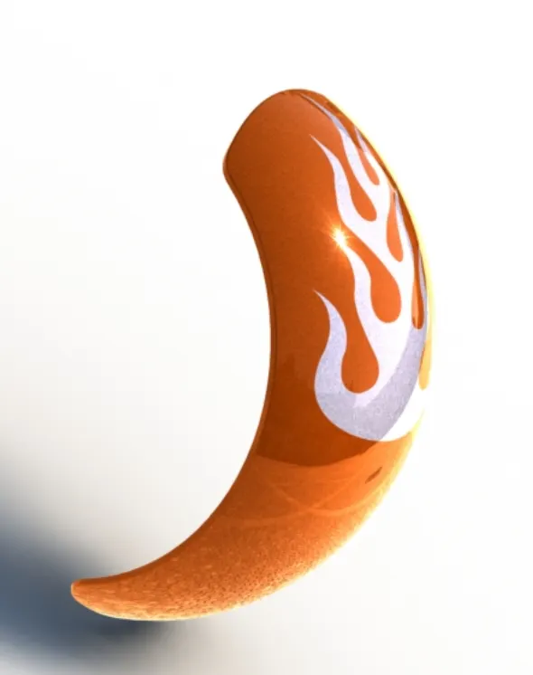
A sketch is created in the front plane using a three point arc and offset it to meet the thickness of the fender. Create an axis at the origin. Using a revolve boss the required rear fender is created. Fillets are created on the sharp edges of the fender: Desired appearance is applied to the fender.
- Chain:
Chain is the connection used to transmit power from the engine to the rear wheel. lt passes over toothed members known as sprockets.
Features used:
- Extruded Boss/Base,
- Linear pattern,
- Circular pattern,
- Fillet,
- Mirror
- Blocks
- Insert blocks
- Combine
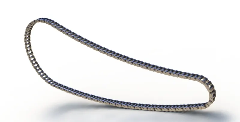
A main profile of the chain is created using three point arc and tangent relations between the arcs using the given dimensions. Create two throwaway sketches which are used to create the inside and outside links of the chain. The plates of the chain links are extruded using the throwaway sketches and the connecting pins are created using the same sketch. Only one side of the plates of the chain links are created. The created chain links are pins then populated on the main sketch using the linear pattern and circular pattern features. All the chain link plates are then mirrored on the front plain. All the components of the chain are combined as a single part using a combine feature. Chrome steel appearance is applied to the chain.
- Oil Tank
Engine oil storage unit of the motorcycle, which ensures it's smooth running and oil is used for lubrication and reduces the heat generated in the gearbox.
Features used:
- Extruded Boss/ Base,
- Combine,
- Shell,
- Fillet
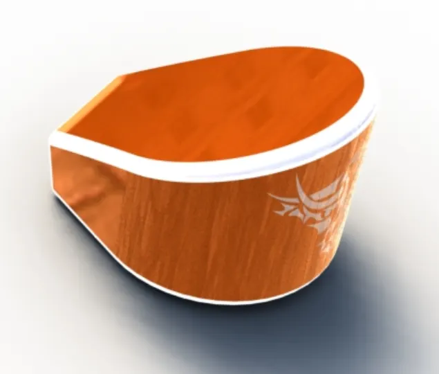
On the top plane create a sketch by 3 point arc and few lines and apply tangent relations. Then extrude the profile to obtain a structure. On the front plane, create another sketch and extrude it using midplane extrude. Now Combine the bodies with common option enabled to obtain the oil tank. Apply necessary fillets. Now using shell features make the oil tank hollow of required thickness. And apply the desired appearance.
- Pedal
The part of the motorcycle where the foot of the rider rests and the place where the gears and brakes approached are easy to the rider.
Features used:
- Extruded Boss/Base,
- Revolve Boss/ Base,
- Dome,
- Linear Pattern,
- Chamfer
- Fillet
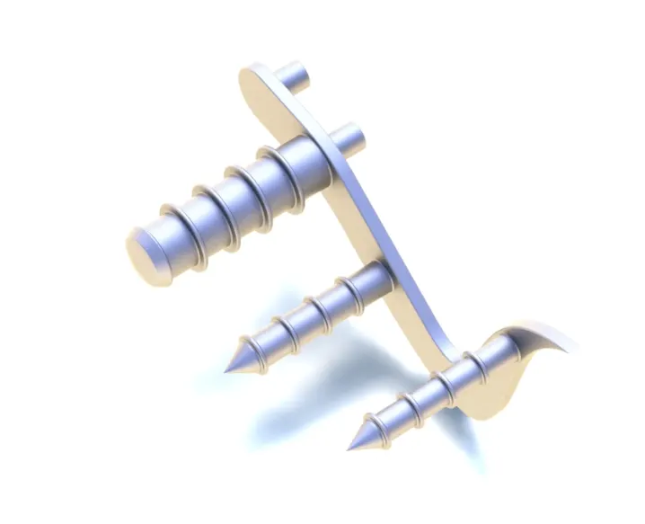
A sketch is made on the front plane in the form of the support plate as shown in the picture above along the few circles of required dimensions on either side of the profile which are later used to produce the extruded cylinders structures for foot rest and attachments to the chassis. Provide the required fillets and linear patterns to produce the ring structures on the pedal. Appearance is provided to the pedals with chrome steel.
- Front wheel
lt is the rolling part situated on the front of the motorcycle. This wheel helps to guide the vehicle according to the movement of the front fork as desired by the rider.
Features used:
- Revolve Boss/Base,
- Extruded Boss/Base,
- Extruded Cut,
- Revolved Cut,
- Circular Pattern,
- Mirror,
- Combine,
- Chamfer,
- Fillet.
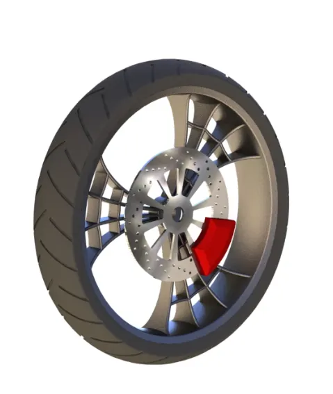
Initially the rim is created by sketching on the front plane and the revolved extruded using an imaginary axis at the origin. A spider web design of the Rim is created on the front plane and is extruded using midplane extrude feature. And this spider web is circular patterned to required numbers and the Rim is completed. The spider web spokes and the rim are combined to form a single solid body.
For Rotor sketch on the front plane and extrude it to the required dimensions. Create the necessary holes using circular pattern.
For Caliper create a profile using lines and circles and remove the unwanted sketch and midplane extrude the caliper profile. Provide necessary fillets and chamfers to complete the caliper.
The Tyre sketch is created by converting entities of the Rim. And the Tyre is revolve extruded. Later profiles are created on the surface of the Tyre to give the gips to the tyres.
Separate appearances are applied to each part of the wheel.
- Rear wheel:
The circular component of the motorcycle which helps in the motion of the vehicle and it receives power from the engine through chain drive. Rim, Tyre, Rotor, Sprocket and Caliper are the parts of the rear wheel.
Features used:
- Revolve Boss/Base,
- Extruded Boss/Base,
- Extruded Cut,
- Revolved Cut,
- Circular Pattern,
- Mirror Combine,
- Chamfer
- Fillet.
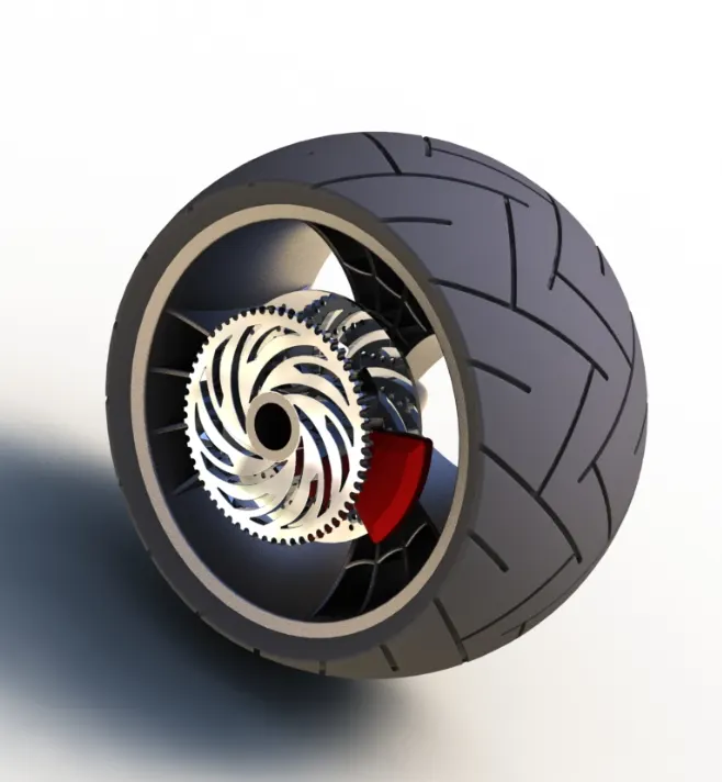
Initially the Rim is created by sketching on the front plane and the revolved extruded using an imaginary axis at the origin. A spider web design of the rim is created on the front plane and is extruded using midplane extrude feature. This spider web is circular patterned to required numbers and the Rim is completed. The spider web spokes and the Rim were combined to form a single solid body.
For Rotor sketch on the front plane and extrude it to the required dimensions. Create the necessary holes using circular patterns.
For Caliper create a profile using lines and circles and remove the unwanted sketch and midplane extrude the caliper profile. Provide necessary fillets and chamfers to complete the caliper
For Sprocket sketch a circle and extrude it to a required thickness. Apply chamfer to the outer edges and create a tooth profile on the extrude and cut it. Apply fillets to the tooth edges and create the sprocket using circular pattern feature and required number of teeth.
For Tyre a sketch is created by converting entities of the Rim. And the Tyre is Revolve extruded. Later profiles are created on the surface of the tyre for making gaps on the tyres.
Separate appearances are applied to each part of the wheel.
- Front Fork
It is used to guide the entire vehicle. It holds the front wheel and other control device operated by the rider. It consists of two columns along With shock absorber which is held together by a triple clamp.
Features used:
- Extruded Boss/Base,
- Revolved Boss/Base,
- Extruded Cut,
- Revolved Cut,
- Project Curves,
- Swept Boss/Base,
- Dome,
- Combine,
- Mirror,
- Chamfer,
- Fillet.
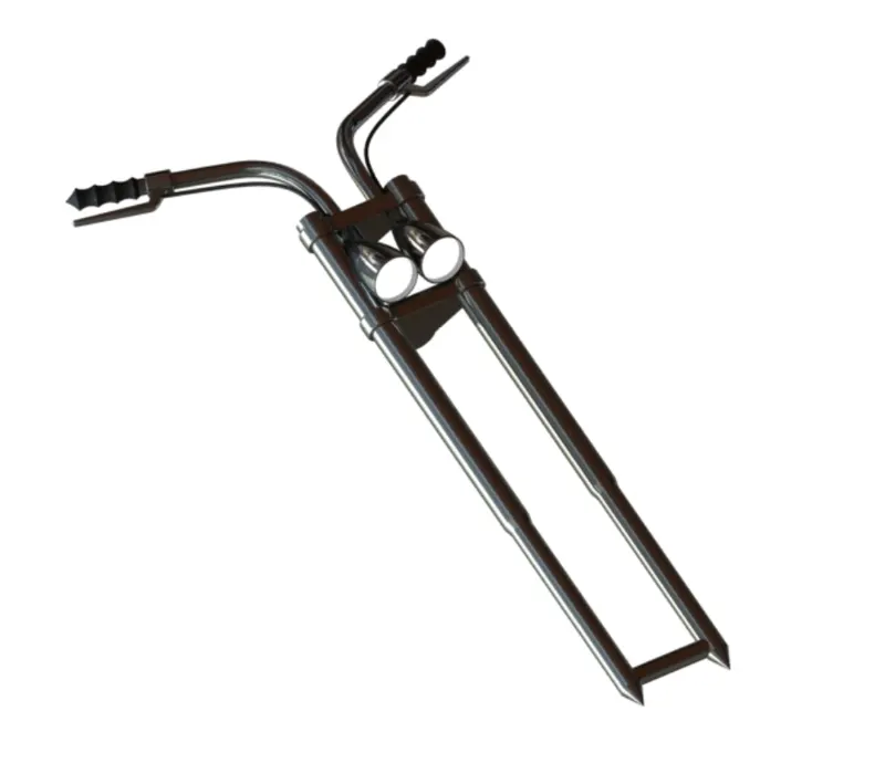
Create the long tube on the front plane by creating the sketches and with appropriate dimensions and then revolve it. Then create the half of the triple clamp using an appropriate dimension sketch. On the same plane create the headlight by revolve extrusion. On the top plane and draw sketches for creating the handle using spline and sweep patterns. Select all the created bodies and mirror them along the front plane and combine the entire object. Select an appropriate appearance to the front fork.
- Chassis
It is the skeleton of the vehicle to which all the components of the motorcycle are attached to. It also provides the required support to the vehicle.
Features used:
- Extruded Boss/Base,
- Revolved Boss/Base,
- Linear pattern,
- Extruded Cut,
- Revolved Cut,
- Project Curves,
- Swept Boss/Base,
- Dome,
- Combine,
- Mirror,
- Chamfer,
- Fillet.
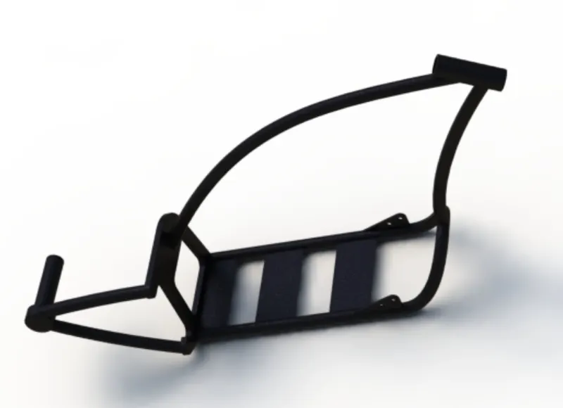
The blueprint of the motorcycle is imported to the part design, by adjusting the location, transparency and the sketch of the chassis is carried on this blueprint. This chassis is made of thickness tubes bent and joined using splines and created/projected curves. At the end all the tubes are connected to a plate and further this chassis is extended till the rear wheel hub.
- Engine
Engine is the main component of the vehicle where the power is generated by burning fuel and later transmitted to the wheel to create the required motion.
Features Used:
- Extruded Boss/Base,
- Revolved Boss/Base,
- Extruded Cut,
- Revolved Cut,
- Circular pattern,
- Project Curves,
- Swept Boss/Base,
- Dome,
- Combine,
- Mirror,
- Chamfer,
- Fillet.
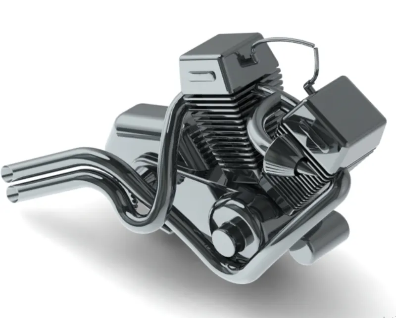
Again using the inserted picture and choosing the front plane, the base of the engine is created using three point Circle and lines (using tangency properties) and extruded to required dimensions. Again using the same sketch extrude the two circles. Again on the front plane create the twin engines in the V-shape. Create the sketch for pulley and create the pulley using revolved extrusion. Create the cylindrical part in the front of the engine on the front plane. Using the curves created and projected curves, create the profile of the exhaust pipes and create the swept boss feature. Then the spark plugs are created at the end. Apply the appropriate material to the engine.
- Fuel / Gas Tank
Fuel storage component of the American Chopper and it supplies the required fuel to the engine.
Features used:
- Swept Surface,
- Loft Surface,
- Boundary Surface,
- Project Curves,
- Knit Surfaces,
- Sweep Cut,
- Combine,
- Shell,
- Mirror
- Fillet.
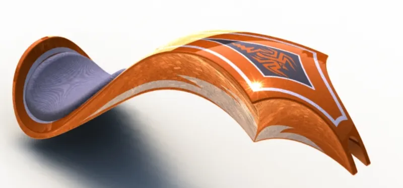
In the front plane using splines, construction lines and projected Curves create a surface sweep to create half of the tank. Create another surface extrude to create the seat. Now mirror the created part of the tank and knit the entire surface together Now apply appropriate materials to the gas tank and the seat.
Assembly of the American Chopper
All the designed components are taken into the assembly section in Solid Works and using different mating.
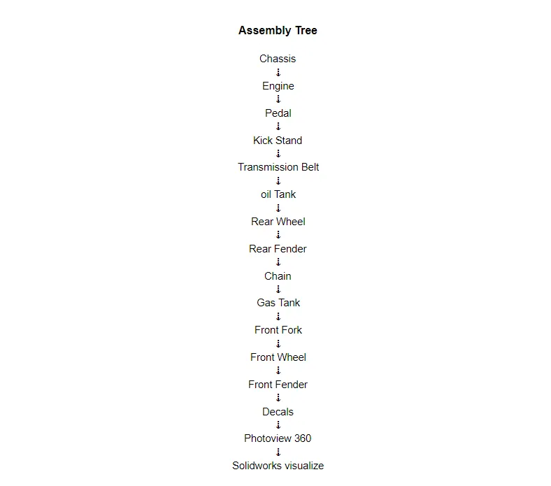
Features used for mating:
- concentric,
- coincident,
- parallel,
- Limit Angle.
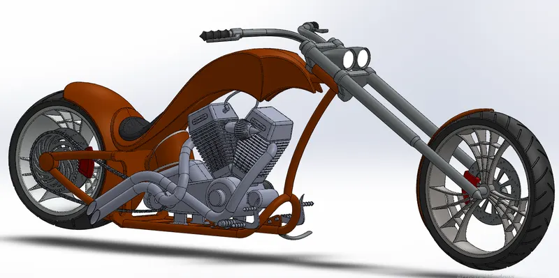
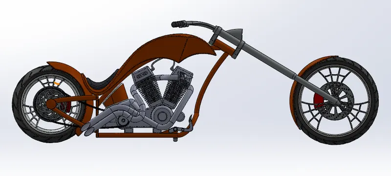
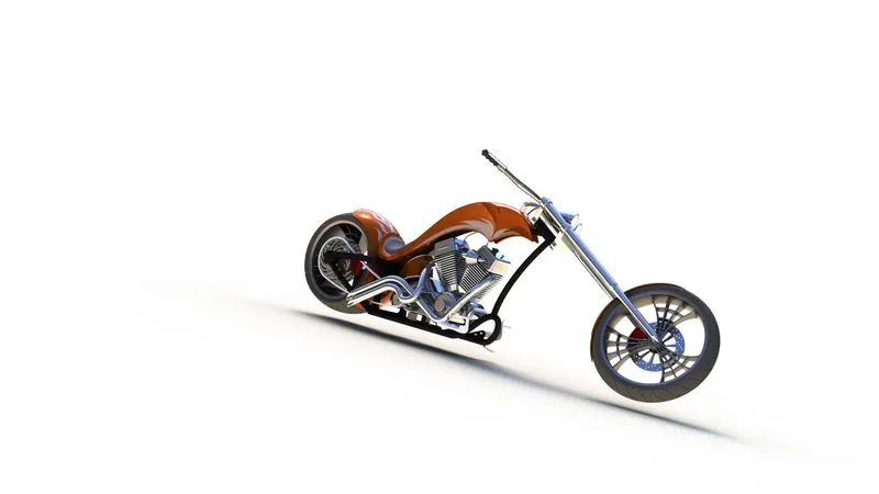
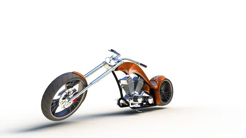
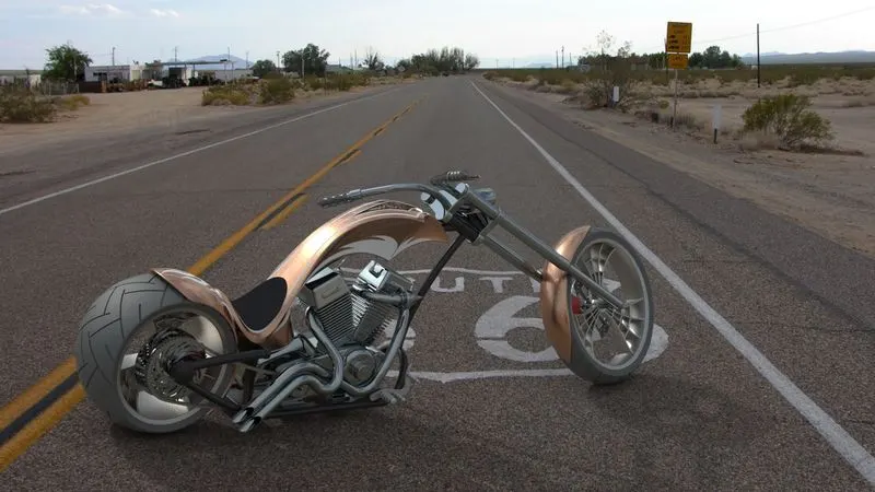
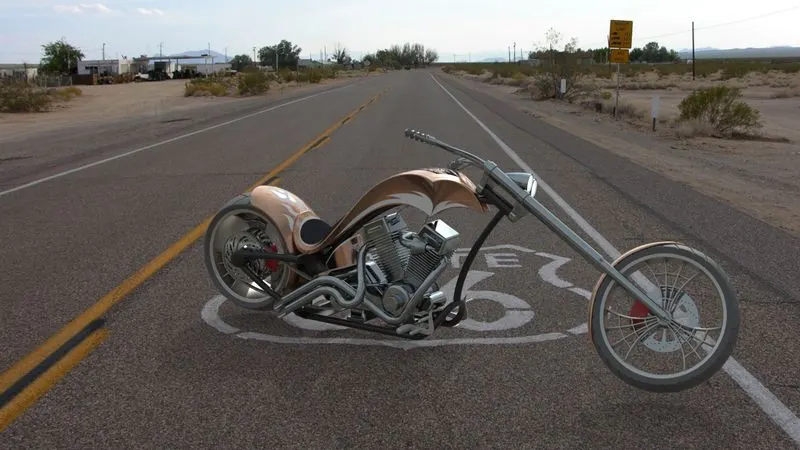
The entire assembly of the American Chopper is created. After assembly the Decals are applied to the Chopper. Once the application of the decals is finished, the assembled motorcycle is taken into Solid Works Visualize or using Photo-view 360. Here various aspects such as camera, external lightnings, background scenes, etc. are taken into consideration before the creation of the final rendering. The final rendered images of the American Chopper are derived.
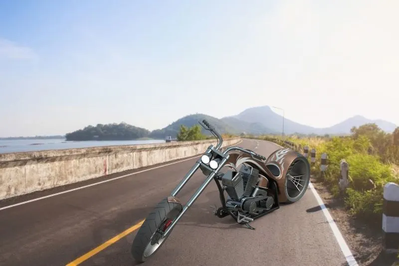
Conclusion:
Thus the American Chopper was modelled, assembled and rendered in solidworks software.