Week 11 - Final project
VEHICLE INTERIOR - DOOR TRIM
This report demonstrates the complete design of an Automotive Plastic Component – Door trim panel from given Class-A surfaces along with master section as an input.
Note:
- Thickness of all the parts as measured from master-section is 2.5 mm.
- The product has been designed using CATIA P3 V5-6R2021
- OBJECTIVE
The aim of this Project is to create the Plastic product DOOR-TRIM INTERIOR from Class-A surfaces along with creation of TOOLING AXIS and B-SIDE FEATURES as per the design rules and OEM standards. In the end DRAFT ANALYSIS for all the parts created has been performed. The following objectives has to be achieved
- To create thickened part using master section as reference.
- To create the mounting features (B-side features) as per master section.
- To perform Draft analysis.
- INTRODUCTION
Modern cars have door panels made of plastic material that are usually created using injection molding. The door panel should match the rest of the vehicle's interior and must have the provision of incorporating other decorative and functional items e.g., switches, controls for windows, locking mechanism, convenience lights, speakers etc. The design must satisfy the necessary aesthetic and the functional requirements such as
- Rigidity
- Surface finish
- Ergonomics
- Uniform wall thickness (prevents defects in the part)
They should be designed to withstand the necessary load while being less than 3 mm in thickness. It should protect the occupants during collisions.
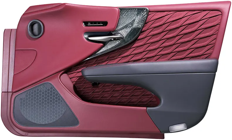
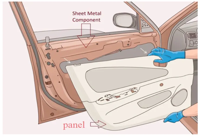
Fig2. shows the placement of door trim panel to the main body of car interior
- TERMINOLOGY
3.1 CLASS A SURFACE:
Class A surface is a surface made by the designer which is the aesthetic part of a car body and is given as an input to the design engineer to create the final product.
3.2 CLASS B SURFACE:
This surface is created by offsetting the class-A surface which is equal to the thickness of the part to be manufactured.
3.3 CLASS C SURFACE:
It is the surface which joins class A with class B surface.
3.4 MASTER SECTION:
Master sections are the guides for design requirements which decide the component packaging after technical (Styling, Concept or Class-A) surfaces. This helps you to decide the feasibility, clearance, the packaging and the fixation strategy before working it on a 3D.
3.5 TOOLING AXIS:
The line along which the mold (CORE and CAVITY) opens. It decides the direction of two mold half opening or closing. The component should clear all the faces of the partin the direction of tooling axis. As a general rule, along tooling axis we must we able to see maximum faces of the component.
There are different methods to create tooling axis. It depends on
- The given surface geometry (face symmetry, surface normal, assembly direction etc)
- Already given direction in input (by customer)
3.6 SIDE CORE AXIS:
- Some features or walls are difficult to clear by the Main tooling axis itself. These features either have negative draft angle or are a part of a sub feature.
- These features need a different tooling direction for clearing the part in the mold.
- This tooling direction is called Side Core Axis which often tends to clear the sub features or walls at different angle with respect to the Main tooling Axis.
3.7 DRAFT ANALYSIS:
It is a tool that allows the designer to check in advance whether the part they are designing can be removed easily from the mold being used to make it.A functional part for injection molding must have draft angles that face both the cavity and core sides. This will reduce the risk of damage to the parts and ensures that part can be ejected from the mold easily. When the draft angle is provided the sticking tendency of the part during removal becomes minimum because as the part ejects contact between surfaces breaks which leads to the reduction in friction and easy removal of the component. Following are the guidelines for providing draft on parts
- Most applications require minimum draft angles of around 0.5º to 1º however 3º draft angles are widely accepted for cost saving purpose.
- 7º Draft angles are given to textured surfaces like Instrument Panels.
- Minimum possible draft angles are given to screw bosses, ribs and stiffeners due to their critical nature i.e 0.5 º.
3.8 PUBLICATON:
Publication is used for easy access of the surfaces or components to work or view them in CATIA workbench.
4. PROCEDURE TO CREATE THE PART IN CATIA
- Create tooling axis for class-A surface.
- Create class-B by extracting and/or offsetting class-A surface.
- Create class-C surface with the help of input class-A surface.
- Join class-A and class-C.
- Trim these joined surfaces with class-B to get a closed surface.
- Create a body from this closed surface.
- Perform draft analysis.
- Create B-Side features as per the given master section.
5. PROCEDURE TO CREATE TOOLING AXIS
5.1 Line normal to surface Method:
In this case if the body has a plane surface and all the faces of the body (when viewing normal this surface) are visible then a line normal to this surface gives the best possible direction of tooling axis.
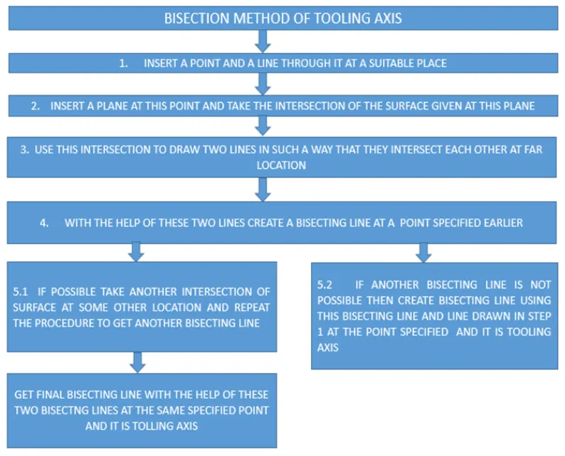
5.2 Bisection Method:
If the part is symmetric about one or more plane, then bisection method is best suitable.
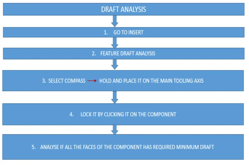
- PROCEDURE TO PERFORM DRAFT ANALYSIS
First ensure that customize view parameter is enabled and material mode is opted in view mode customization.
The given class-A surface has the following components
- Bottle holder
- Lower substrate
- Upper substrate
- Arm rest
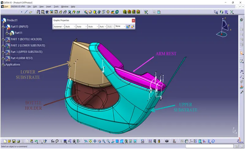
Fig3. These components have to be created as 3D to make door trim panel.
- BOTTLE HOLDER
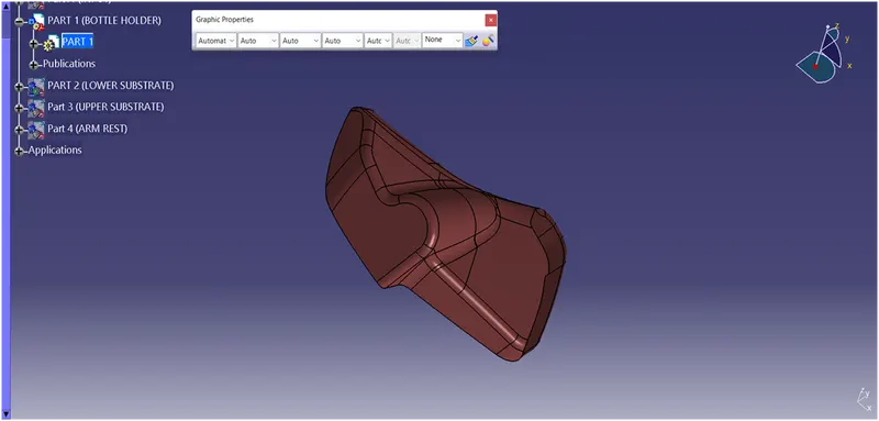
Fig4. Class-A
a. CREATION OF TOOLING AXIS
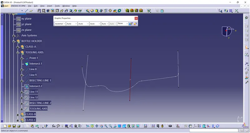
Fig5. First bisecting line to create the main tooling axis
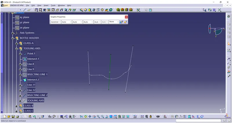
Fig6. Second bisecting line to create the main tooling axis
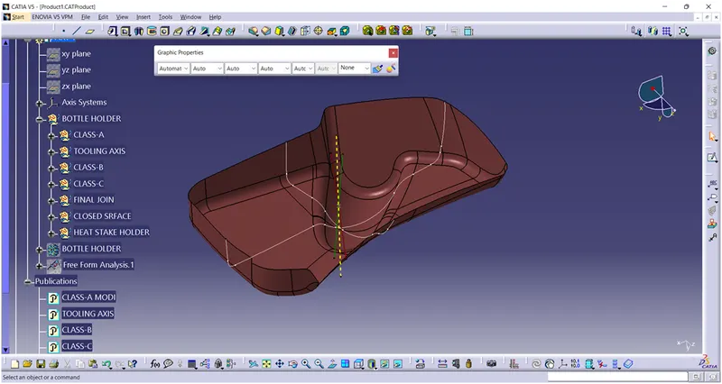
Fig7. Main tooling axis (Yellow)
b. CREATION OF CLASS-B SURFACE
By using multi-section, fill, extrapolate, boundary, offset, join and trim features, class-B has been created.
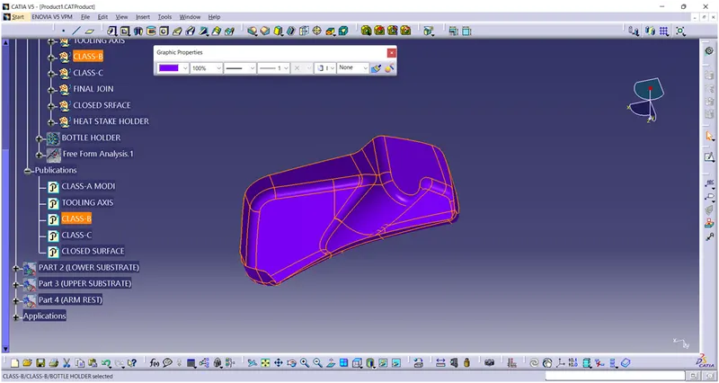
Fig8. Class-B surface
c. CREATION OF CLASS-C SURFACE
By using multiple extract, sweep, and extrapolate features class-C has been created.
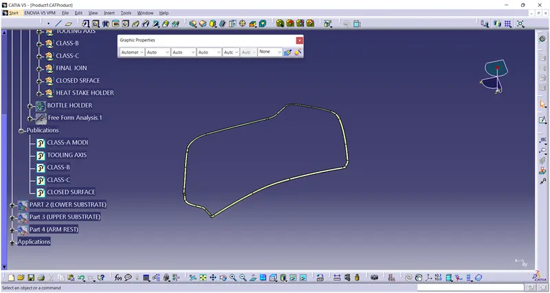
Fig9. Class-C surface
d. CREATION OF CLOSED SURFACE
By using trim feature closed surface has been created.
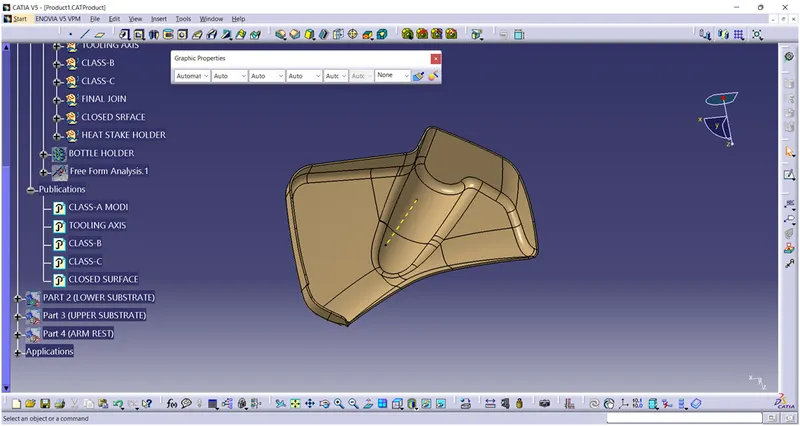
Fig10. Closed surface
- CREATION OF CLOSED BODY
By using insert body and close surface feature closed body has been created.
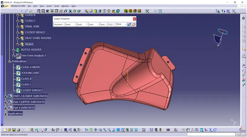
Fig11. Closed body with B-Side features
- DRAFT ANALYSIS
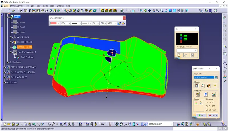
Fig12. Draft analysis of class-A at 3o
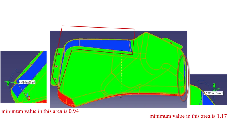
Fig13. Draft analysis of class-A at 3o
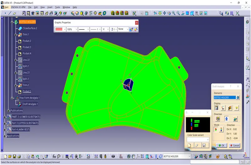
Fig14. Draft analysis of class-A body 0.9
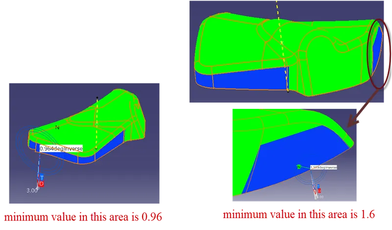
Fig15. Draft analysis of class-B at 3o
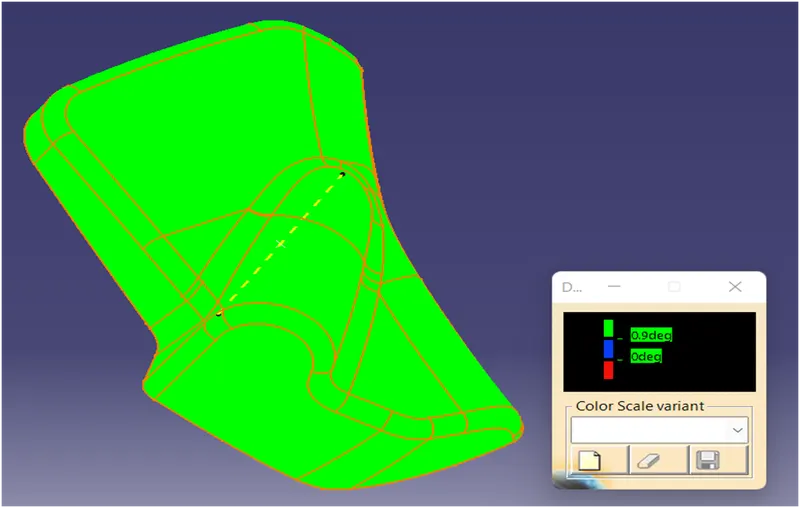
Fig16. Draft analysis of class-B at 0.9 o
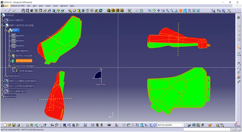
Fig17. View of FINAL body with B-side features in different orientations
- LOWER SUBSTRATE
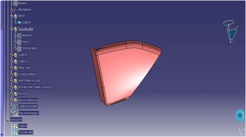
Fig18. Class-A
a. CREATION OF TOOLING AXIS
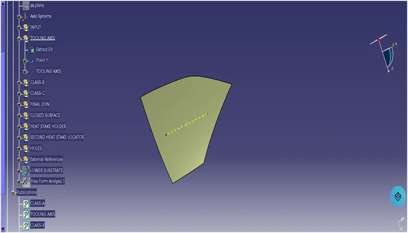
Fig19. Creation of tooling Axis
b. CREATION OF CLASS-B SURFACE

Fig20. Class –B
c. CREATION OF CLASS-C SURFACE
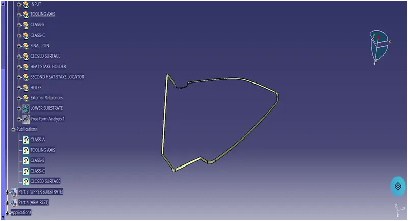
Fig21. Class –C
d. CREATION OF CLOSED BODY
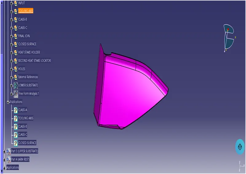
Fig22. Closed body
e. DRAFT ANALYSIS OF CLOSED BODY
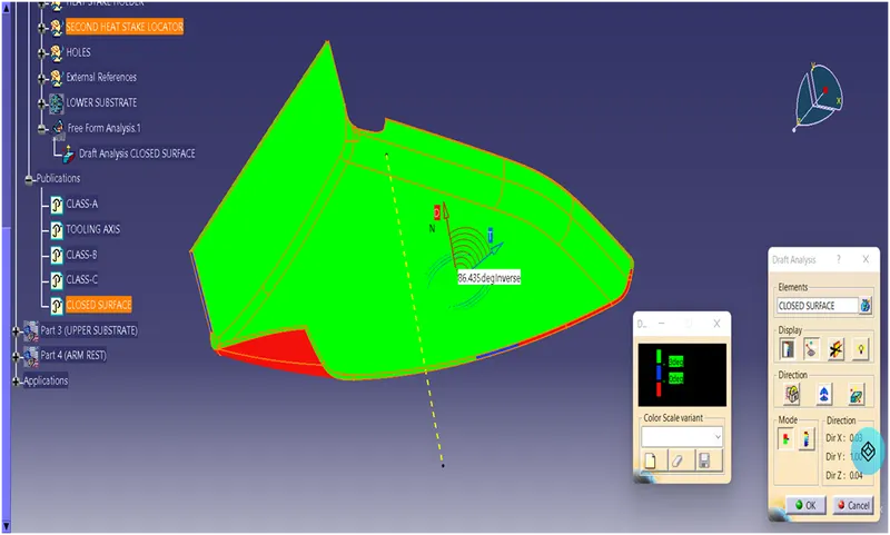
Fig23. Draft analysis of closed body at 3o
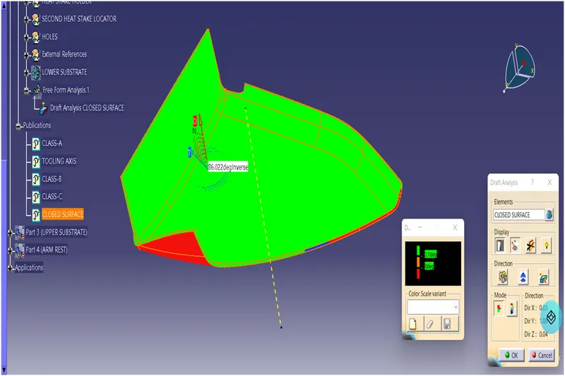
Fig24. Draft analysis of class-B at 2.7 o
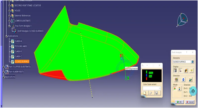
Fig25. Draft analysis of closed body at 0.5 o
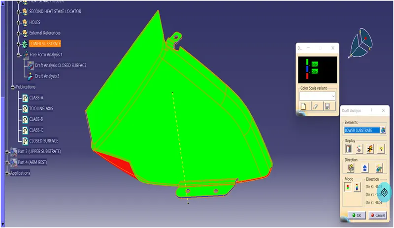
Fig26. Draft analysis of closed body with B-side features at 3 o
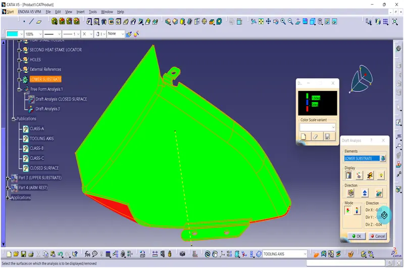
Fig27. Draft analysis of class-B at 1.5 o
- UPPER SUBSTRATE
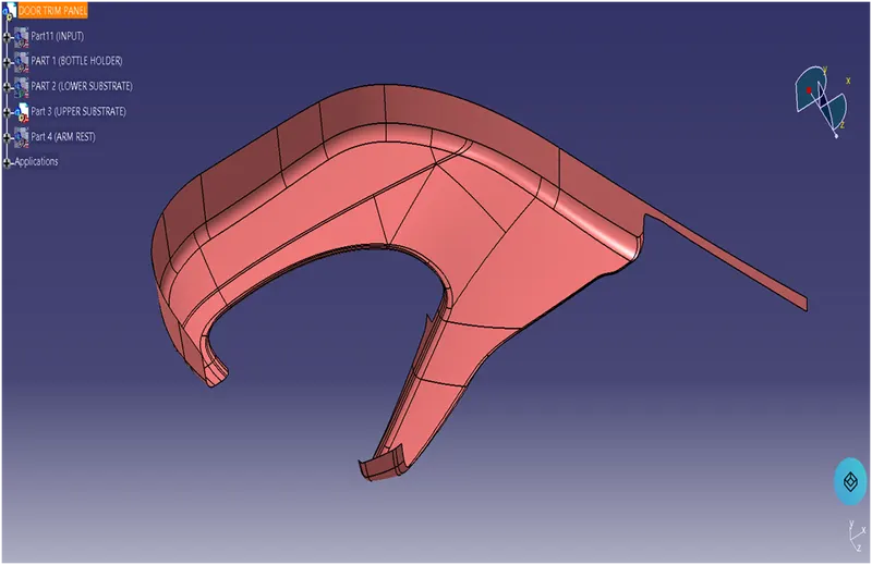
Fig28. Class A
a. CREATION OF TOOLING AXIS
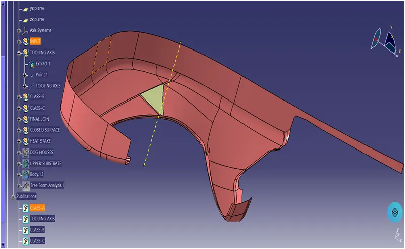
Fig29. Main Tooling Axis
b. CREATION OF CLASS-B SURFACE
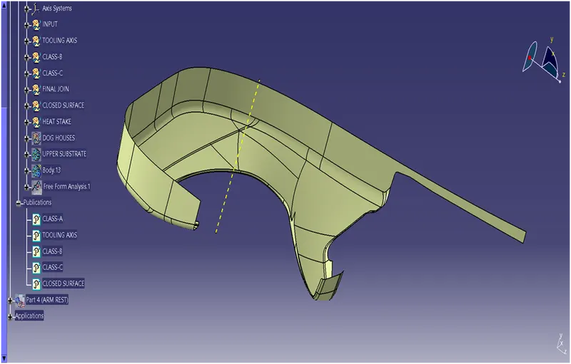
Fig30. Class –B
c. CREATION OF CLASS-C SURFACE
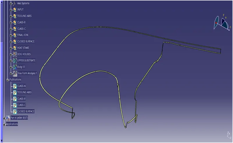
Fig31. Class –C
d. CREATION OF CLOSED BODY
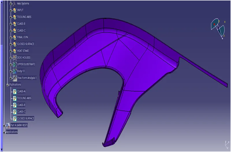
Fig32. Closed surface
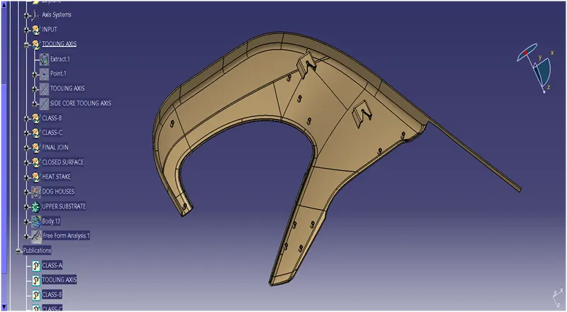
Fig33. Closed body with B-Side features
e. DRAFT ANALYSIS OF CLOSED BODY
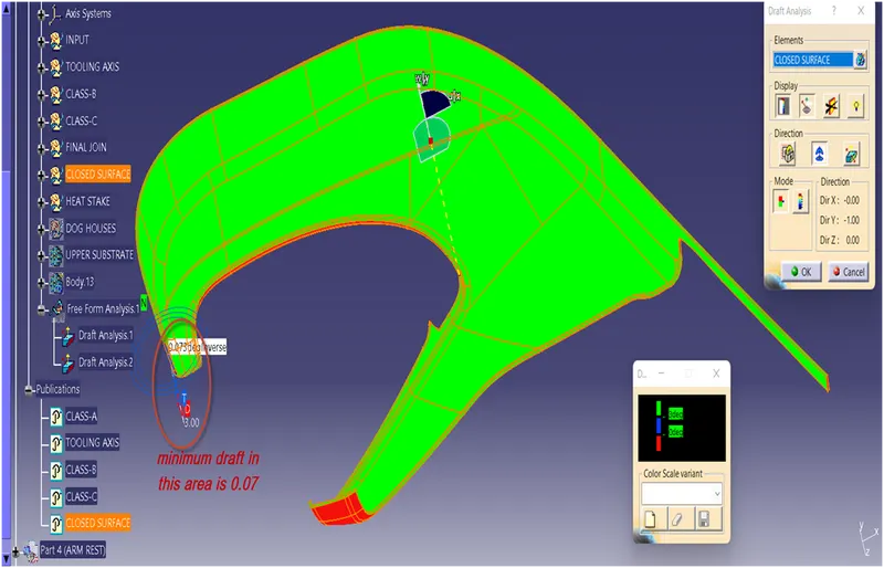
Fig34. Draft analysis of closed body at 3 o
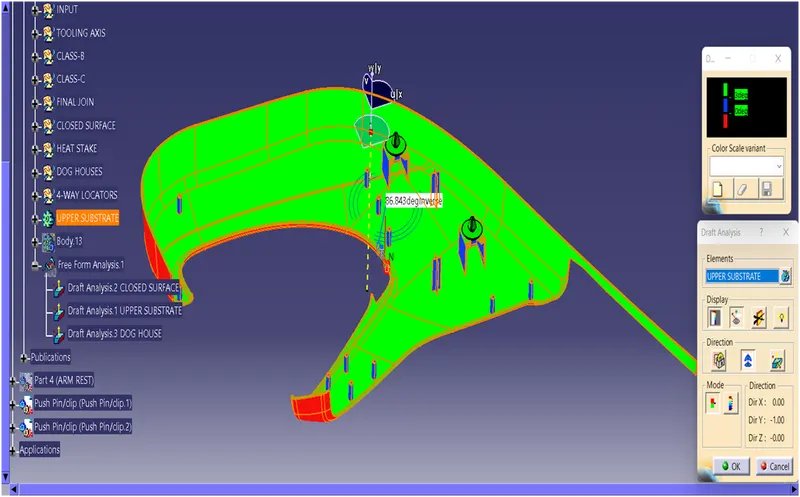
Fig35. Draft analysis of closed body with B-Side features at 3 o
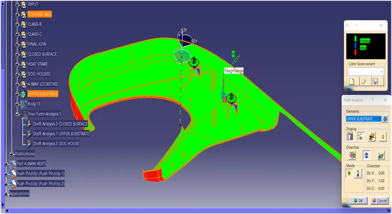
Fig36. Draft analysis of closed body with B-Side features at 0.48 o
f. DRAFT ANALYSIS OF DOG HOUSE
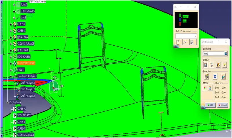
Fig37. Draft analysis of dog house at 0.48 o
- ARM REST
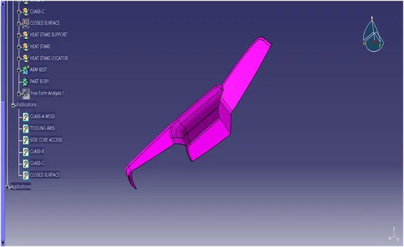
Fig38. Class-A
a. CREATION OF TOOLING AXIS
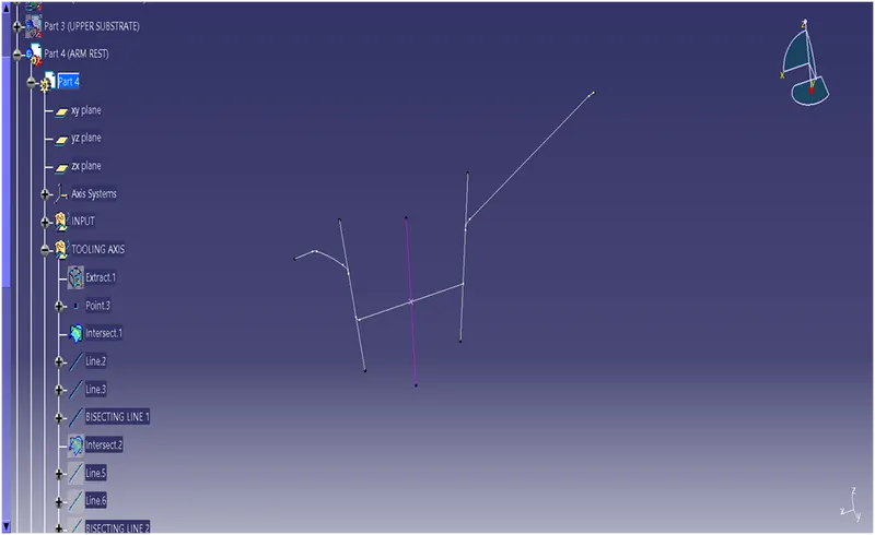
Fig39. Creation of first bisecting line
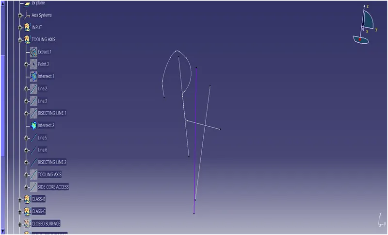
Fig40. Creation of second bisecting line
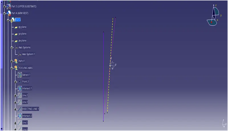
Fig41. MAIN TOOLING AXIS (YELLOW)
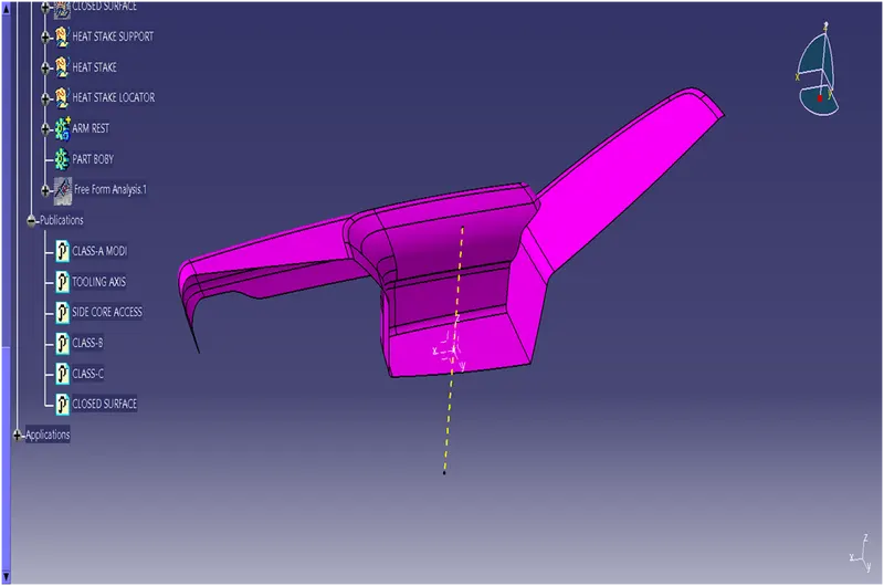
Fig42. Class-A
b. CREATION OF SIDE CORE AXIS
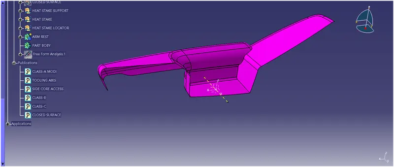
Fig43. Creation of SIDE CORE AXIS
c. CREATION OF CLASS-B SURFACE
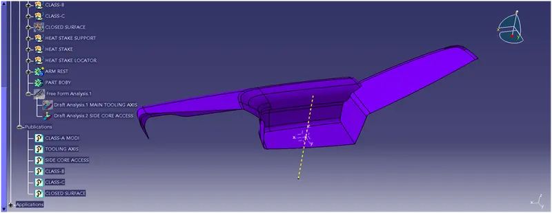
Fig44. Creation of Class-B
a. CREATION OF CLASS-C SURFACE
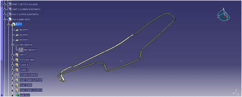
Fig45. Creation of class-C
d. CREATION OF CLOSED SURFACE
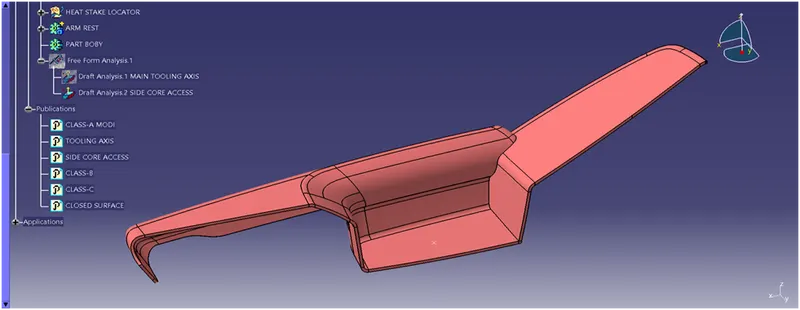
Fig46. Creation of closed surface
e. DRAFT ANALYSIS OF ARM REST
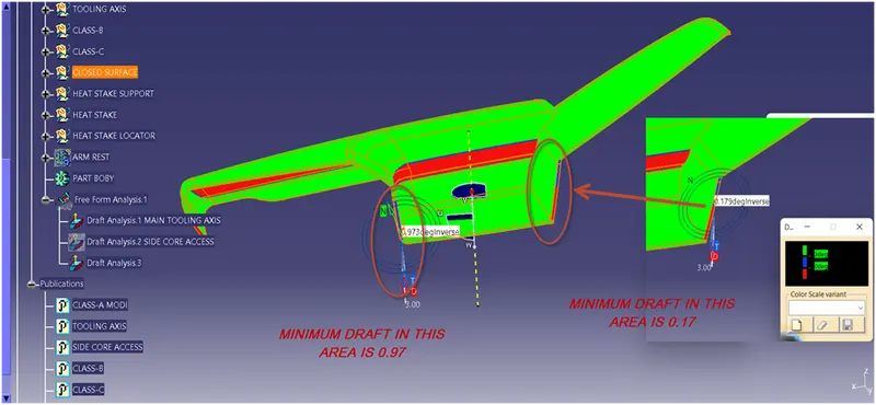
Fig47. Draft analysis of class-B at 3 o
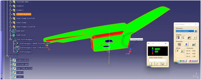
Fig48. Draft analysis of class-B at 0.75 o for main tooling axis
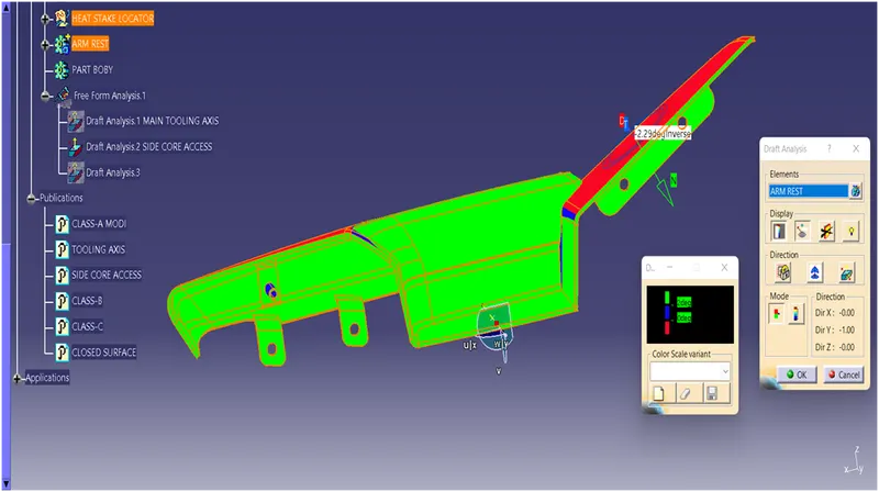
Fig49. Draft analysis of class-B at 2 o
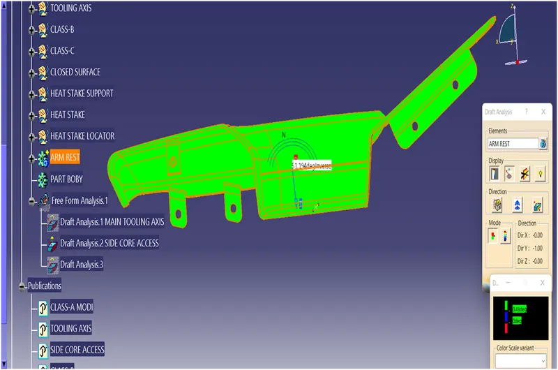
Fig50. Draft analysis of closed body with B-side features at 0.48 o
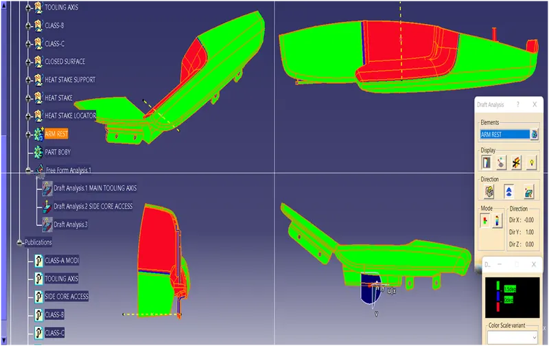
Fig51. Draft analysis of body with B-Side features at 2 o in different orientations
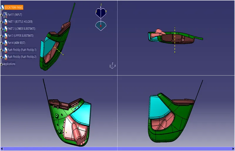
Fig52. FINAL DOOR TRIM
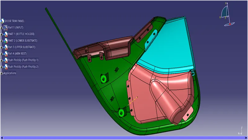
Fig53. B-side of door trim panel
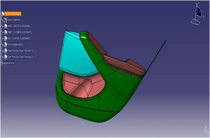
Fig54. FINAL FINISHED DOOR TRIM PLASTIC COMPONENT
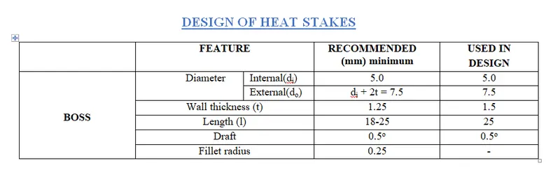
DESIGN OF DOG-HOUSE (PUSH PIN LOCATORS)
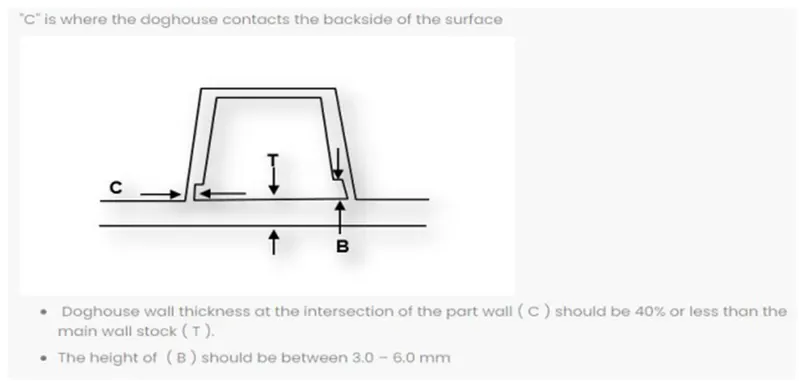
Fig 55. https://skill-lync.com/challenges/question/98958/1048/383244
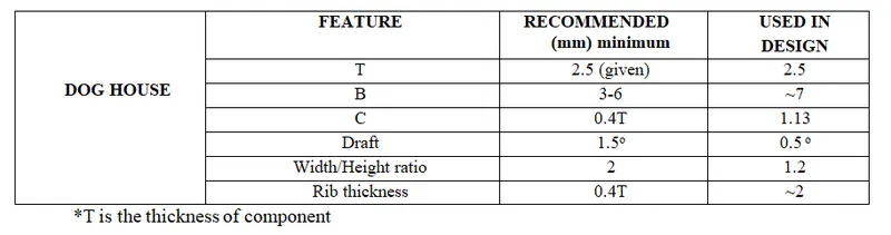
THE FOLLOWING FIGURES SHOWS THE CATIA FEATURES USED IN DESIGN OF DOOR TRIM
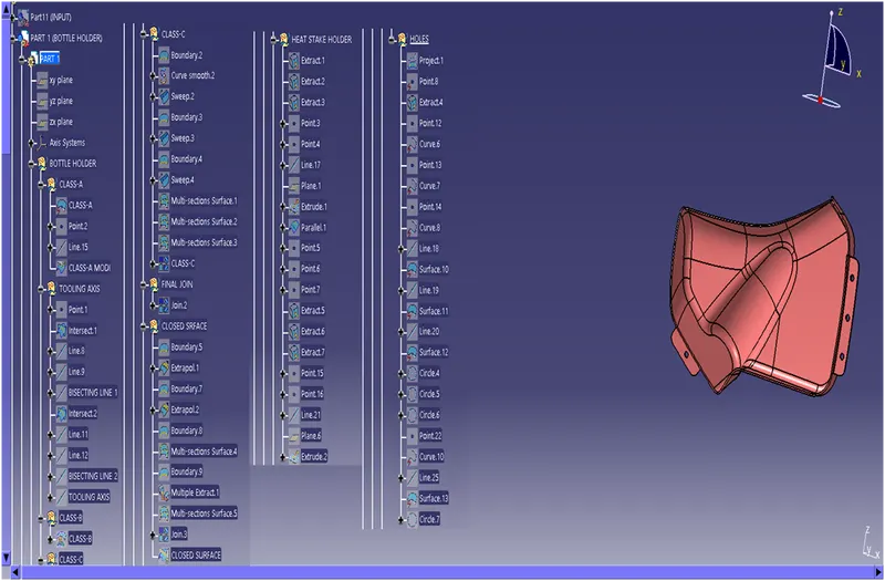
Fig 56.
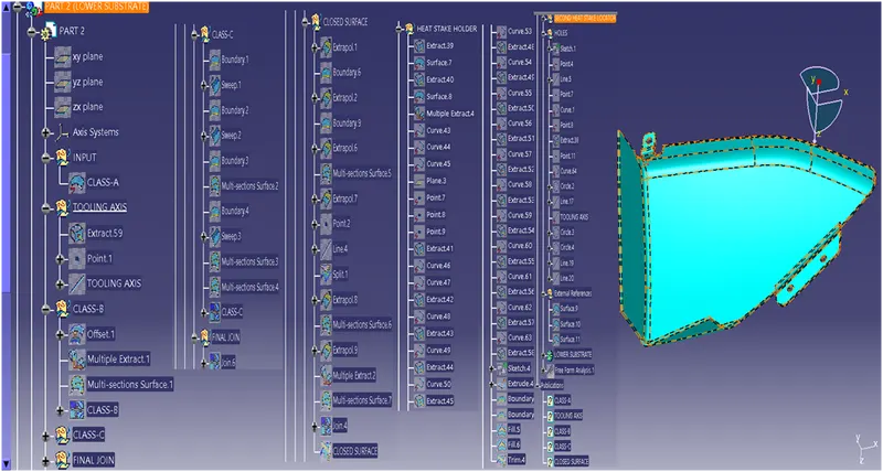
Fig 57.
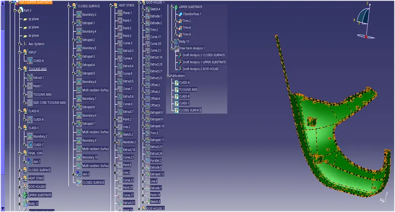
Fig 58.
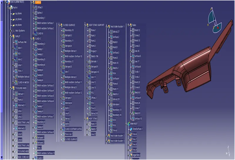
Fig 58.