Week 8 - Challenge 3 - Coin Holder Design
COIN HOLDER
This report demonstrates the complete design of an Automotive Plastic Component – Coin Holder from a given Class-A surface as an input.
Note:
- Thickness of the component is 2.5 mm.
- The component is designed using CATIA P3 V5-6R2021
OBJECTIVE
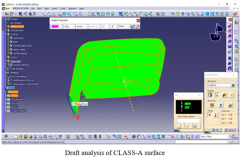
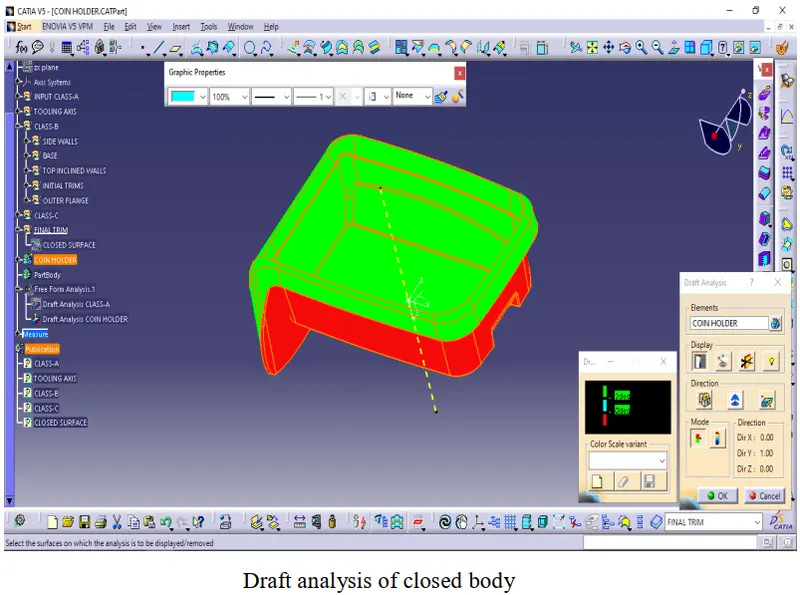
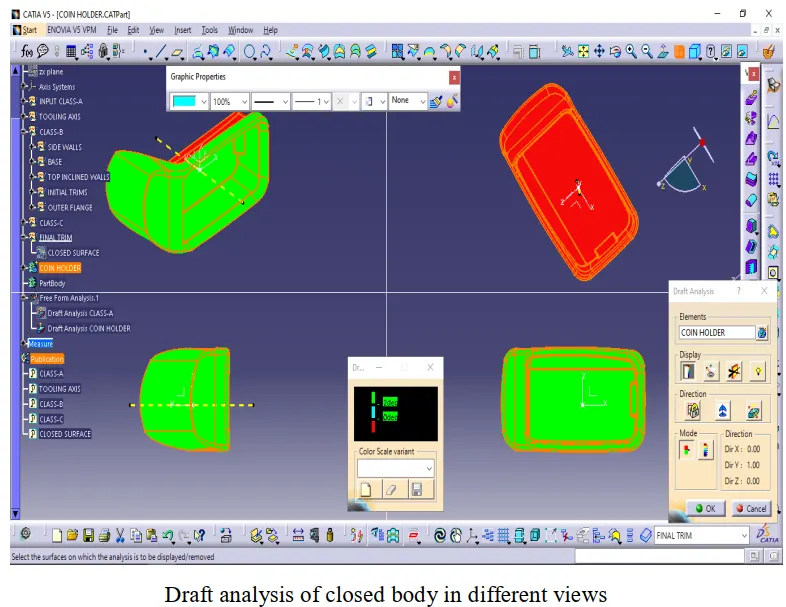
The aim of this Project is to create the Plastic component COIN HOLDER from ClassA surface along with creation of TOOLING AXIS. In the end DRAFT ANALYSIS for CLASS-A along with the closed body has also been performed.
INTRODUCTION
TOOLING AXIS:
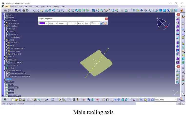
The line along which the mold (CORE and CAVITY) opens. It decides the direction of two mold half opening or closing. The component should clear the tooling axis in the given specific direction. As a general rule, along tooling axis we must we able to see maximum faces of the component.
There are different methods to create tooling axis. It depends on
- The given surface geometry (face symmetry, surface normal, assembly direction etc)
- Already given direction in input (by customer)
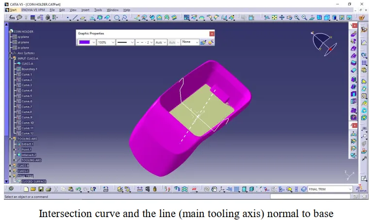
In this case as the body has a flat surface so a line normal to this surface gives the best possible direction of tooling axis. Hence a line drawn normal to the base of coin holder will be our tooling axis. Bisection method of tooling axis creation can also be used in this case and for this we can use the intersection curve as shown in the tooling axis figure shown below in the document.
DRAFT ANALYSIS:
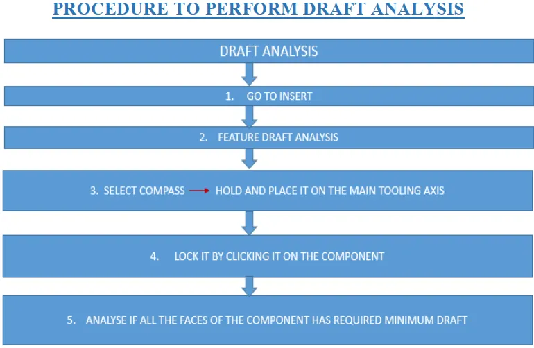
It is a tool that allows the designer to check in advance whether the part they are designing can be removed easily from the mold being used to make it. A functional part for injection molding must have draft angles that face both the cavity and core sides. This will reduce the risk of damage to the parts and ensure that part can be ejected from the mold easily.
When the draft angle is provided the sticking tendency of the part during removal becomes minimum because as the part ejects contact between surfaces breaks which leads to the reduction in friction and easy removal of the component.
Generally a 3 degree draft angle is recommended on the surfaces and 0.5 degree on ribs and screw bosses.
PUBLICATON:
Publication is used for easy access of the surfaces or components to work or view them.
PROCEDURE TO CREATE THE TOOLING AXIS
If the component is symmetric about one or more plane then bisection method is best suitable. The procedure is as following:
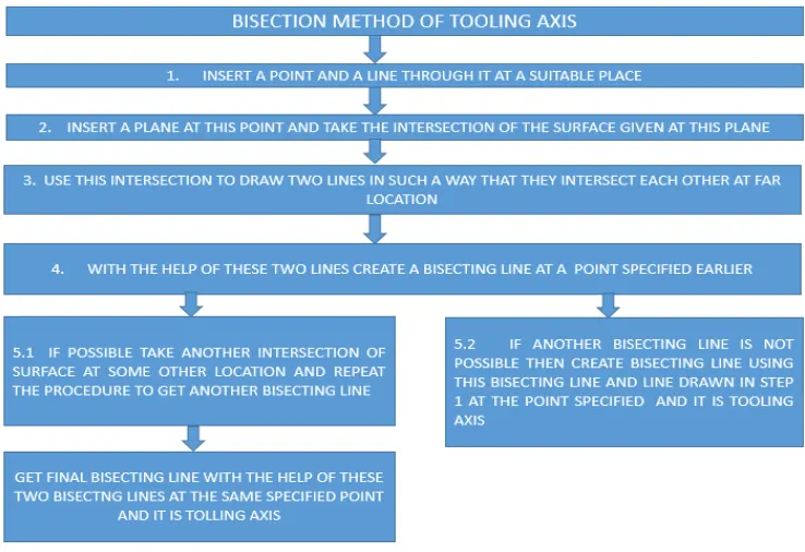
For the given surface the tooling axis is normal to base of the component. Bisection method
can be used to create it using the intersection curve as shown in figure. Refer the following
diagram.
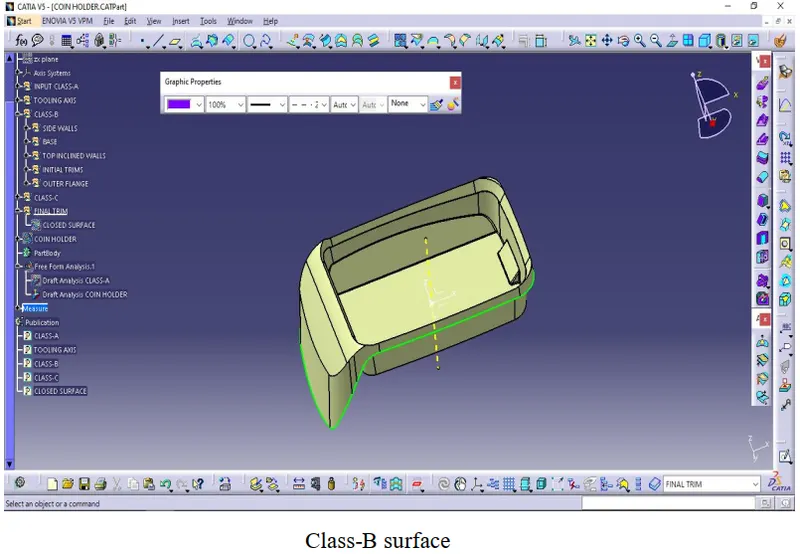
CREATION OF CLASS-B SURFACE
By using extract, untrim, extrapolate, offset, join and trim features class-B has been created.
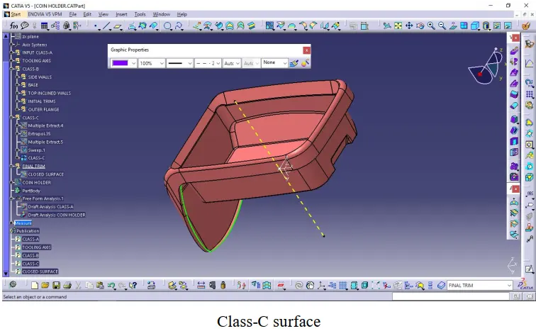
CREATION OF CLASS-C SURFACE
By using multiple extract, sweep, and extrapolate features class-C has been created.
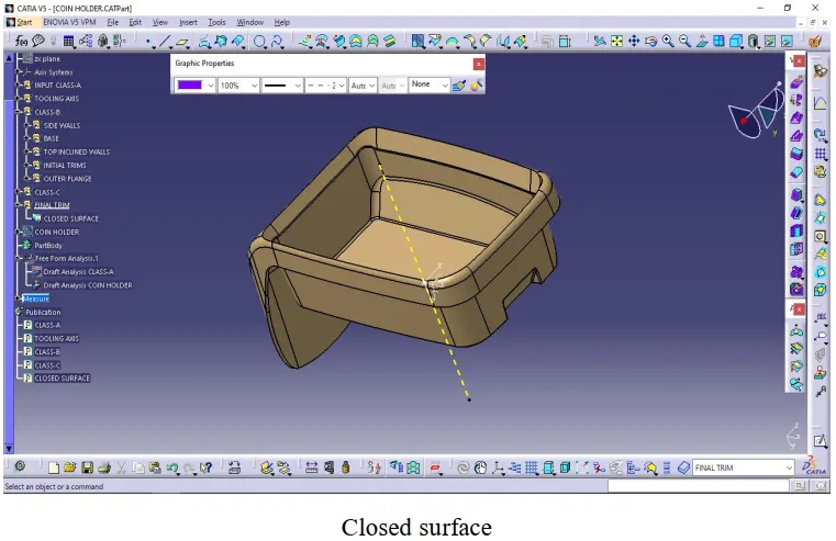
CREATION OF CLOSED SURFACE
By using trim feature closed surface has been created.
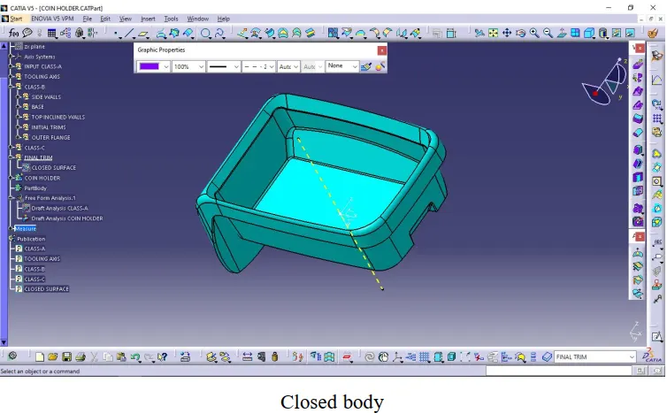
CREATION OF CLOSED BODY
By using insert body and close surface feature closed body has been created.