Week 11 - Final project
AIM:
Development of a Door Trim panel.
OBJECTIVE:
To make a Door trim panel in Catia V5 using the given Class A surface.
ABSTRACT:
This project contains the brief theory on how the approach has been made inorder to obtain the solid door trim panel. It also show case certain rules regarding the maufacturing of plastic components. Draft analysis of the Class A surface and creation of
Class B as well as Class C is also described here.
APPROACH: Our basic approach for creating the solid from the Class A surface will be:
1) Make the tooling axis
2) Run the Draft analysis
3) Create Class B surface
4) Create Class C surface
5) Trim all together to create a required closed body.
5) Provide solid to the closed body.
CLASS A SURFACE:
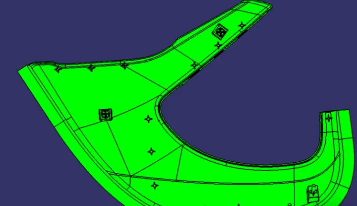
In automotive industry various teams works on various components, a car for example is not entirley designed by a single designer. There are many teams among which the task o making various components is distributed. And this is followed for every department of the industry. In this project we are given class A surface which is designed in other software like Autodesk Alias, by a Class A designer. This is aesthetic surface and a lot of time, effort and good experience are demanded for making this continuous and a good flowing surfac model. This is the major reason why, when we get this as input we are not allowed as a plastic designer to make any improvements in the Class A surface. Rather, it should be brought to the attention of the seniors which later is conveyed to the concerned team and take care of.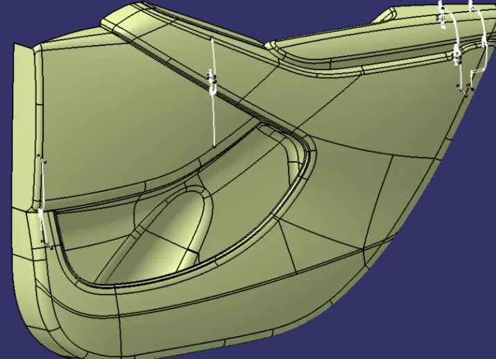
TOOLING AXIS:
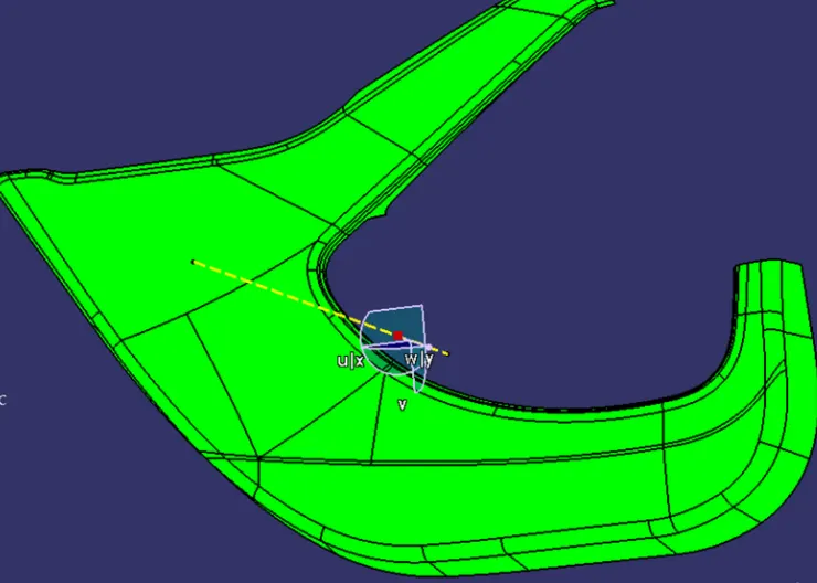
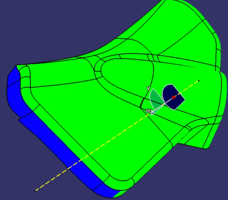
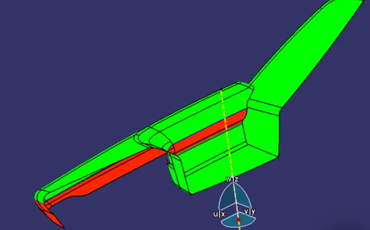
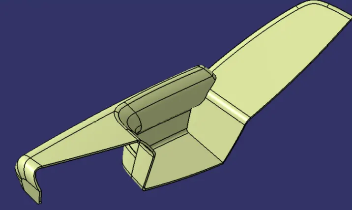
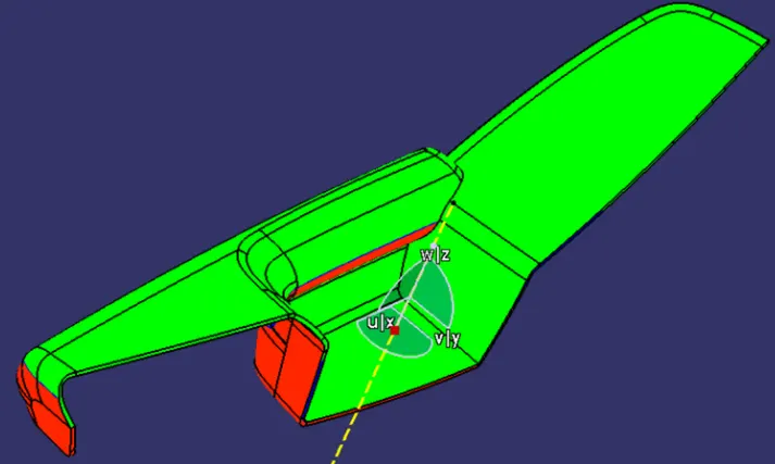
Tooling axis is the axis along which the core and cavity opens and closes. It is very important to define the tooling axis in the first step while designing a component as it is the main component which helps us to run draft analysis on class A at initial stage to see if we can move ahead. Also for later stage, tooling axis is the direction along which Class c surface and the draft to the components are given. In this model we have a tooling axis in the perpendicular direction to the entire dooe trim that is y-direction in the model. It is very evident that arm rest will require a side core, so another tooling direction is made specially for arm rest . Apart from these two tooling axises we also have a side core tooling axis for dog house.
DRAFT ANALYSIS:
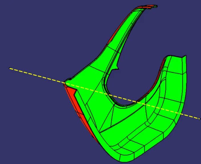
Our first step before starting the model should always be to check is the surface has enough draft that it will not create any probelms while ejecting from the mold. This seems like a big task as we have to foresee something that will come at very later stage. But this i done by a small process called draft analysis. This analysis tells us whether our componen will be safely ejected in the tooling axis we have provided. Some components require side core where ther are under cuts, holes or pojections on the side walls, so for this we need a different tooling axis and a different analysis is required to check those areas. Draft analysi shows color codes which are defined by the user for different values which also are define by the user. These colors helps us to analysis if the component is clearing the draft analysi and we are good to go ahead or not. In case the component fails the analysis for Class A then we have to submit the draft analysis report to the higher authority so that surface of the component can be improved. Failing analysis simply means that the component does not have the required draft value it must have. In case our solid model which we develop
ARM REST:
DESIGNING PLASTIC COMPONENT
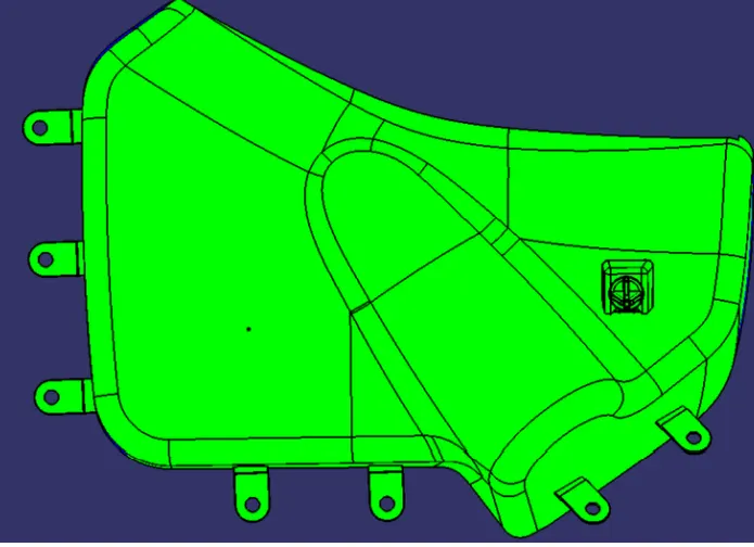
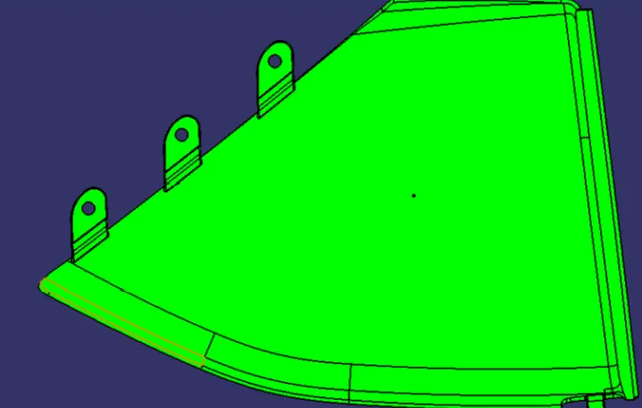
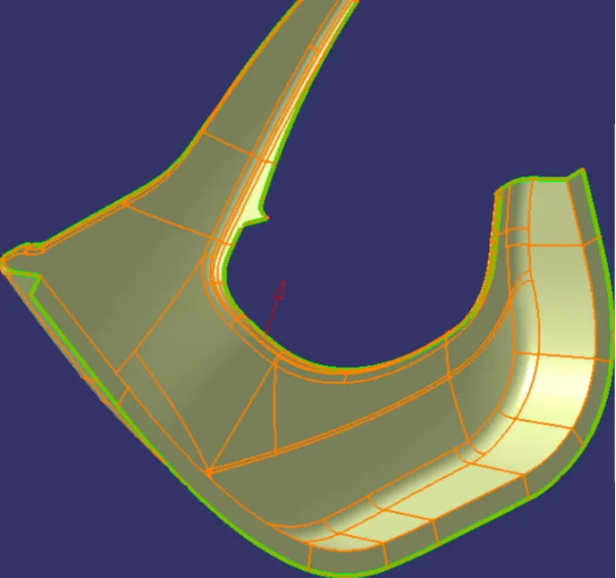
As the entire door panel is divided into various components, we will make this plastic component in the same way. Following steps have been carried out to make the plastic component for every component. The first step for every component was same. The input was not a single unit buit has numerous patches. These patches were joined together using join command thus after performing this operation we got our single class A surface. Once we get a class A surface, we have to proceed to make class B surface. Creating class B by extracting every flat surface will be complex process in such component. So we directly offset it by 2.5 mm. For making class C surface we have used sweep command
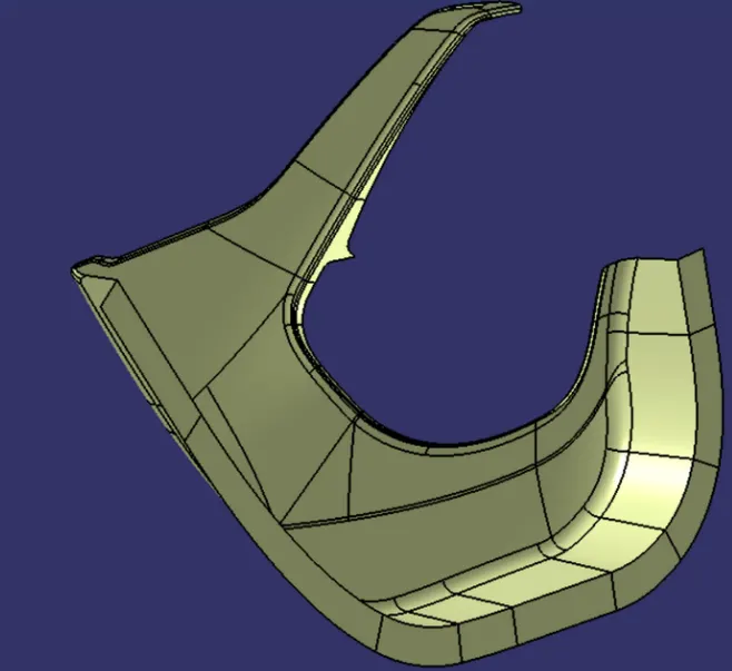
with draft direction by giving 3 deg draft angle and tooling axis as direction. But at many places this did not work so we have to sweep with reference surface at 90 deg. Once that was done,the C surface was joined together using join command. To make a final surface model, we have to trim all the three surfaces together and later go to part design to close the surface.
HERE ARE THE IMAGES OF EVERY COMPONENT IN THE ORDER OF THE ABOVE STEPS:
LOWER SUBSTRATE:
Joining of flanged Class A surface together.Class B surface was created by offseting to 2.5mm from class A surface. This is the nomina
thickness of the component
Now created C surface along with class A and class B surface by trimming and made it asa closed body.
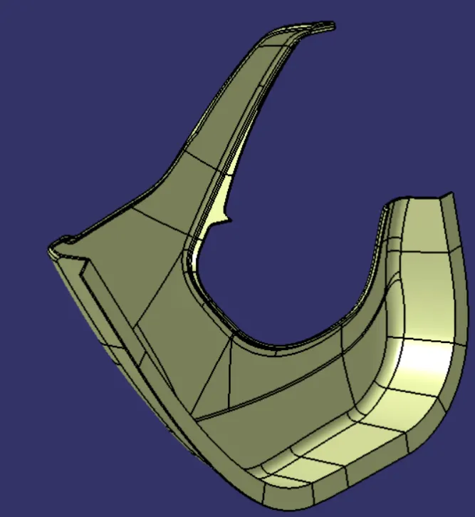
Once we get the surface model, we make it into solid model by going to part design and closing the surface. Once that is done, we run draft analysis on the component and once it is clear, we move ahead with making B side features and again run a draft analysis on the entire component. Below image shows the analysis on lower susstrate component after making all the features
MAP POCKET 1:
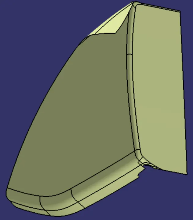
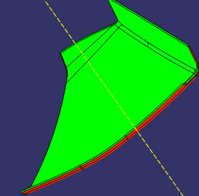
MAP POCKET 2:
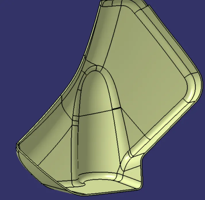
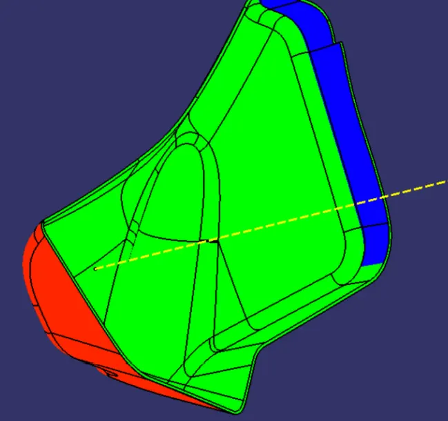
ARM REST:
DESIGNING B SIDE FEATURES:
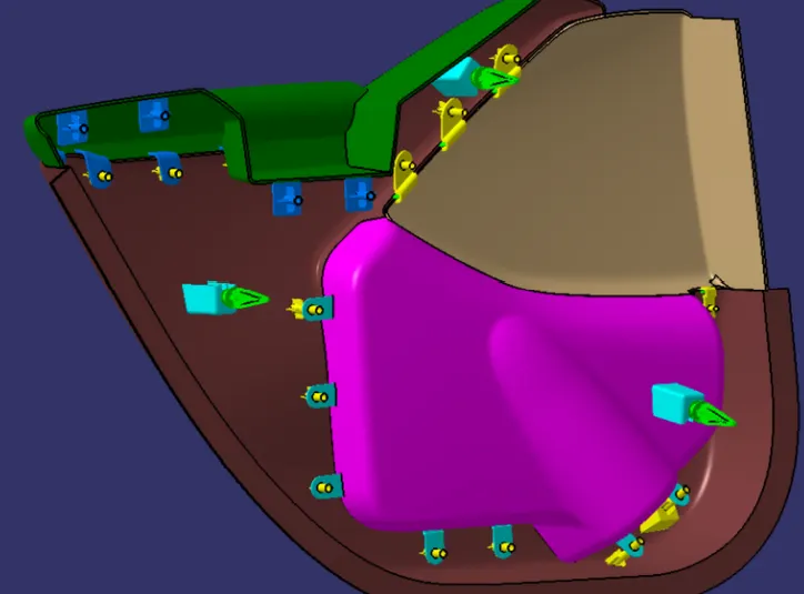
DOG HOUSE: Primary function of the dog house is to avoid sink marks. But it also helps in other things like if the mating part is to be at a greater distance then we cannot make the height of the screw boss of that greater height, thus we make dog house and mount screw boss on it. Hence it helps in solving the probelm of screw boss and also it helps to have perpendicular screw boss. There are certain guidelines to be followed while creating the dog house which followed in the project properly.
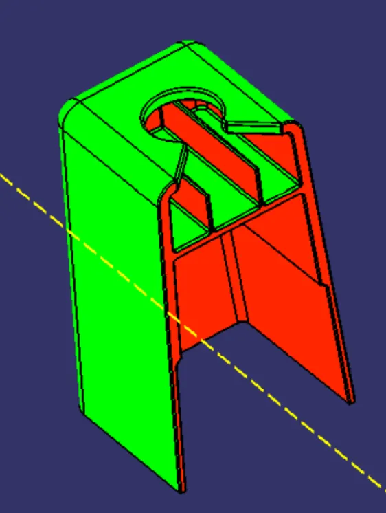
Inside faces are clearing with 0.5 deg in lifter axis.
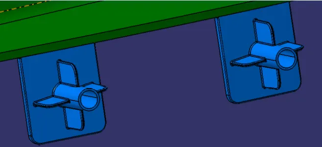
SCREW BOSS:
They are used for the purpose of mating two parts. They have hole in them which acceptes the threaded part of the fasteners such as screws.
RIBS:
They increases the stiffness and strength without increasing overall wall thickness of the model which is not desired. They also facilitate:
1) Locating and arresting components of an assembly.
2) Providing alignment in mating parts.
3) Acting as stopper or guides for mechanisms
DRAFT ANALYSIS ON DIFFERENT PARTS AFTER ADDING THE B SIDE FEATURES:
LOWER SUBSTRATE: