Week 11 - Final project
OBJECTIVE:
*To create the thickned part using master section for refference.
*To create the mounting features are per design guidelines in the industry and with master section.
*To perform draft analysis & tooling analysis.
INTRODUCTION:
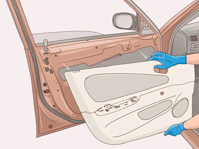
The door panel is the interface between the interior of the car and the inner workings of the door. generally the door pane is divided into two parts of easy designing like arm rest,map pocket,lower substrate,bottle holder.these requires one of the toughest requirement among the interior parts of the car.this should be designed to with stand the load while being less than 2mm in the thickness ansd alsso protect the occupants during collisions.
INPUT OF CLASS A SURFACE
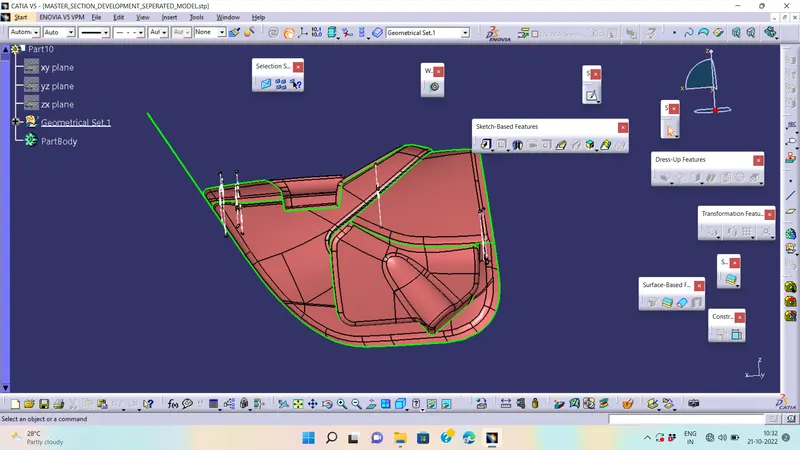
DEVELOPMENT PROCESSES WILL BE CLEARLY MENTIONED BELOW
1) PART-1 (SURFACE-SOLID CONVERTION PROCESS)
2)PART -2(B SIDE FEATURES ADDING PROCESS)
PART-1
PROCEDURE OF DOOR TRIM PANEL :
The door panel is divided into four parts for easly to design. There are,
- Door Arm Rest.
- Lower substrate.
- Upper Map Pocket.
- lowerMap Pocket.
1. DOOR ARM REST:-
- After receving the Class-A for the connectivity of the surfaces on it.
- Use boundary operation and disassemble.
- Check for discontinuous Surface.
- The check is over if any discontinuities do not arise.
- Identify faces which can potentially create problems while manufacturing.
- Surfaces at angles along a desired Tooling Axis.
- Extract a plain surface and create a point on its center for Axis system creation.
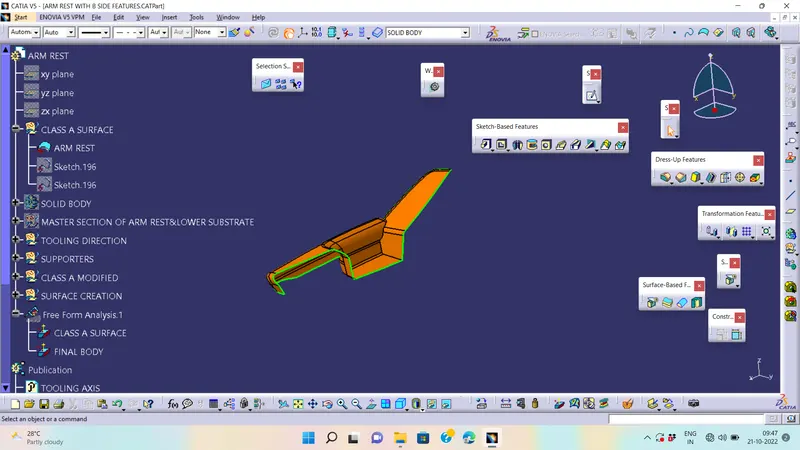
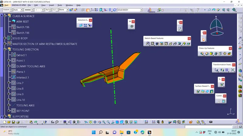
Draft Analysis on Class-A :-
- Change View Mode Customization to Material mode.
- Go to INSERT--->ANALYSIS--->FEATURE DRAFT ANALYSIS and move the compass to the moving Axis.
- WE ARE FINDING given A class surface is not clearing draft anlysis inform to styling team
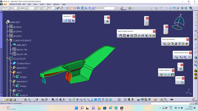
Class-B Surface Creation :-
This can be done by offseting the class-A surface and by reparing the patches that are forrmed while offsetting the class-A surface.
- First offset the class-A surface
- We can observe it has created patches
- So we have to repair them by using multi section surface command.
- create Class-B Surface and make it publish.
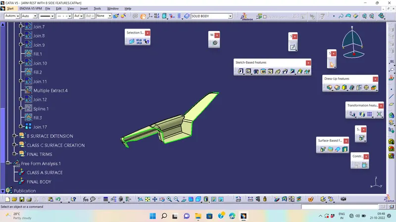
Class-C Surface Creation :-
- Extract Class A boundary and convert to Smooth Curve.
- Sweep the curve to the Class A.
- Sweep value should be greater than the Thickness required for part.
- Join the Class A Surface with the Class C surface to create a single surface entity.
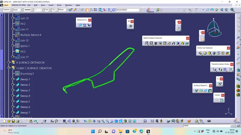
Closed Surface Creation :-
- Trim the obtained surface with Class B surface.
- Make Slight Adjustments by extrapolating small values and trimming to obtain a final Enclosed Surface.
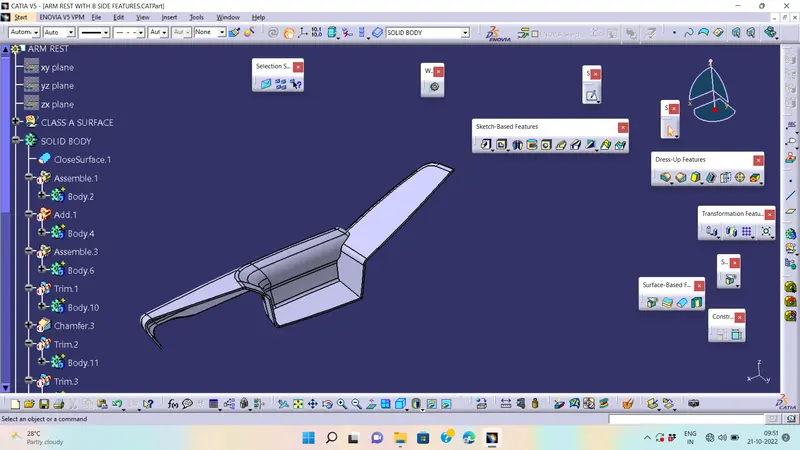
- The final Enclosed Surface Obtained is shown in Figure.
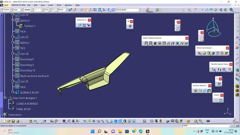
by using closed surface command make a surface to solid convertion
Perform Draft Analysis on Final solid body :-
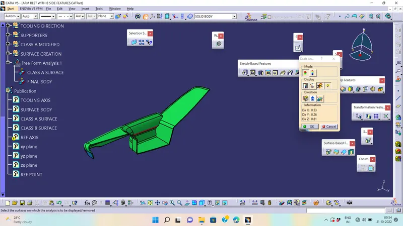
- Change View Mode Customization to Material mode.
- Go to INSERT---> ANALYSIS---> FEATURE DRAFT ANALYSIS and move the compass to the Main Tooling Axis.
- Change the range to 3°. Apply the settings as shown if Figure.
2. LOWER SUBSTRATE:-
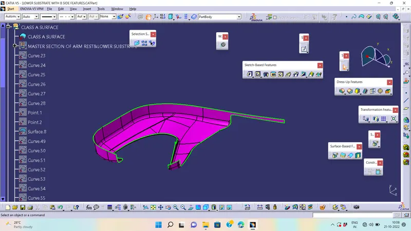
- After receiving the Class-A for the connectivity of the surfaces on it.
- Use boundary operation and disassemble.
- Check for discontinuous Surface.
- The check is over if any discontinuities do not arise.
Determine the tooling Axis :-
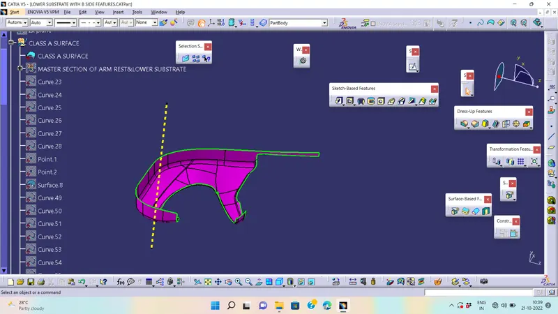
- Identify faces which can potentially create problems while manufacturing.
- Surfaces at angles along a desired Tooling Axis.
- Create the intersection by using the plane.
Draft Analysis on Class-A :-
- Change View Mode Customization to Material mode.
- Go to INSERT--->ANALYSIS--->FEATURE DRAFT ANALYSIS and move the compass to the moving Axis.
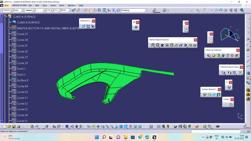
Class-B Surface Creation :-
This can be done by offseting the class-A surface and by reparing the patches that are forrmed while offsetting the class-A surface.
- First offset the class-A surface
- We can observe it has created patches
- So we have to repair them as we required commands to produces shape
- create Class-B Surface and make it publish.
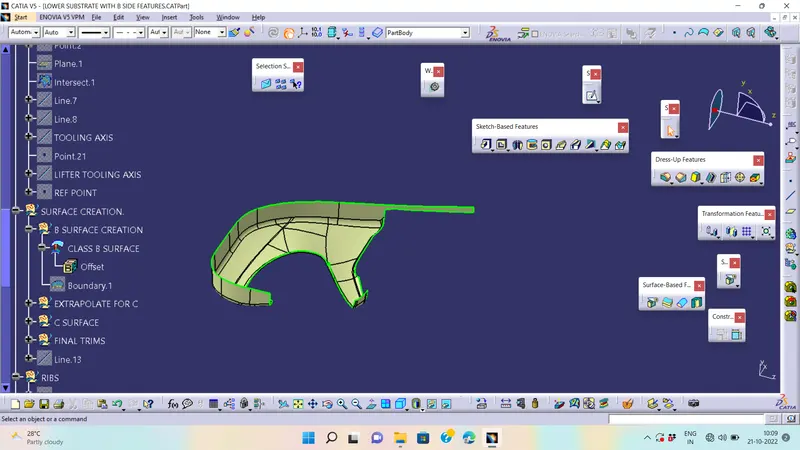
Class-C Surface Creation :-
- Extract Class A boundary and convert to Smooth Curve.
- Sweep the curve to the Class A.
- Sweep value should be greater than the Thickness required for part.
- The obtained sweep is shown in Figure.
- Join the Class A Surface with the Class C surface to create a single surface entity.
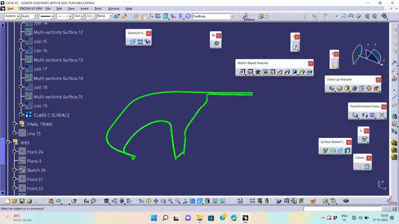
closed Surface Creation :-
- Trim the obtained surface with Class B surface.
- Make Slight Adjustments by extrapolating small values and trimming to obtain a final Enclosed Surface.
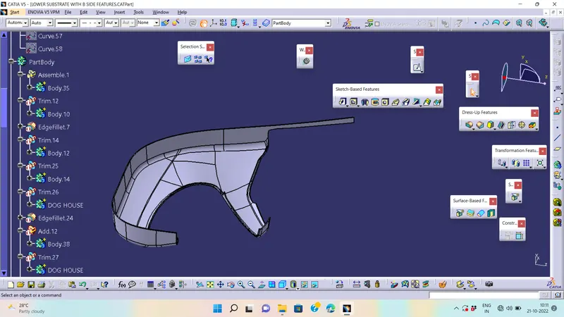
- The final Enclosed Surface Obtained is shown in Figure
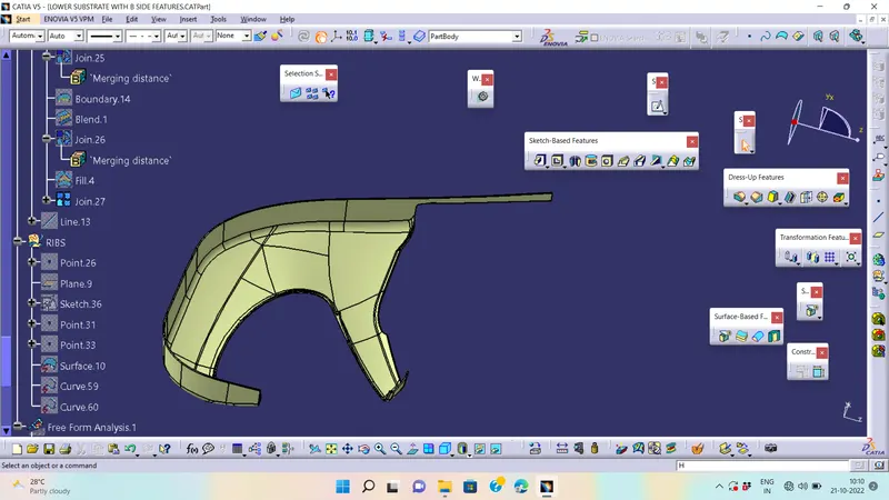
by using closed surface command make a surface to solid convertion
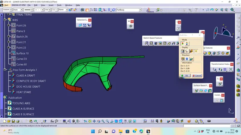
Perform Draft Analysis on Final solid body :-
- Change View Mode Customization to Material mode.
- Go to INSERT---> ANALYSIS---> FEATURE DRAFT ANALYSIS and move the compass to the Main Tooling Axis.
- Change the range to 3°. Apply the settings as shown if Figure.
3. UPPER MAP POCKET:-
- After receiving the Class-A for the connectivity of the surfaces on it.
- Use boundary operation and disassemble.
- Check for discontinuous Surface.
- The check is over if any discontinuities do not arise.
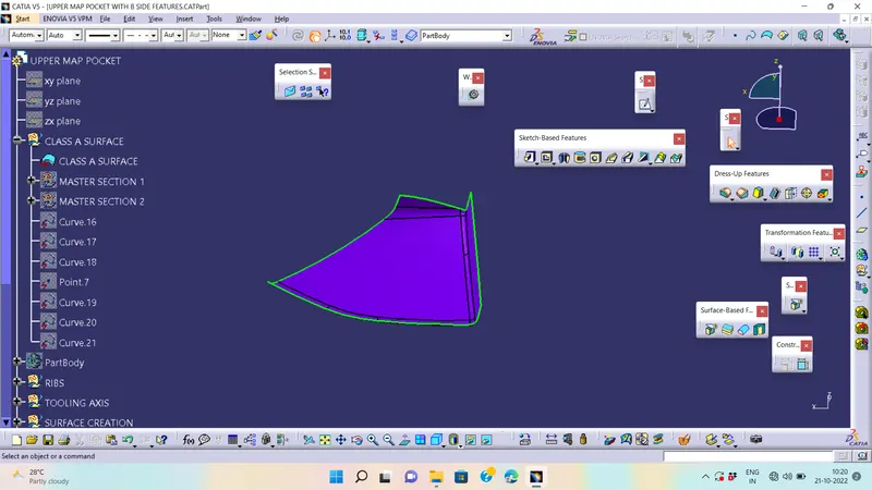
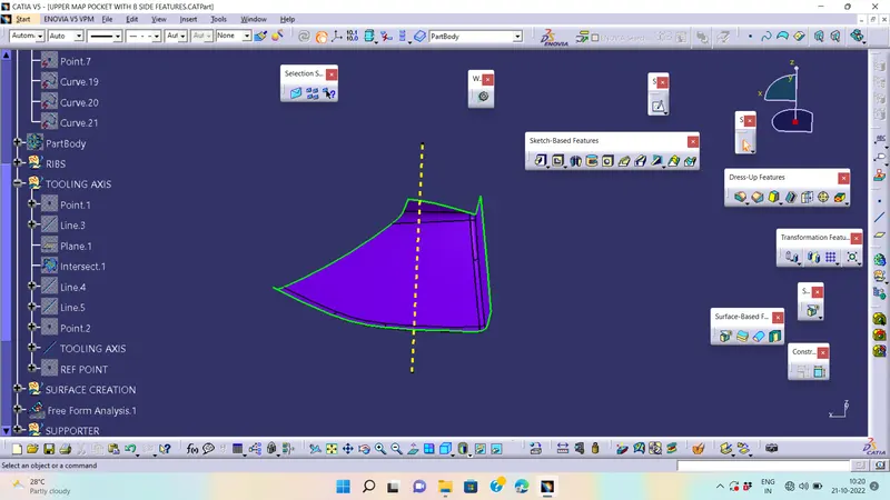
Determine the tooling Axis :-
- Identify faces which can potentially create problems while manufacturing.
- Surfaces at angles along a desired Tooling Axis.
- Create the intersection by using the plane.
DRAFT ANLYSIS FOR CLASS A :-
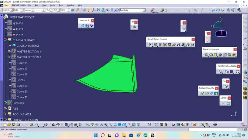
Class-B Surface Creation :-
- The creation of class-B surface can be done by smiply offsetting the class-A surface to the required distance and required direction.
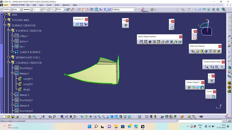
Class-C Surface Creation :-
- Extract Class A boundary and convert to Smooth Curve.
- Sweep the curve to the Class A.
- Sweep value should be greater than the Thickness required for part.
- The obtained sweep is shown in Figure.
- Join the Class A Surface with the Class C surface to create a single surface entity.
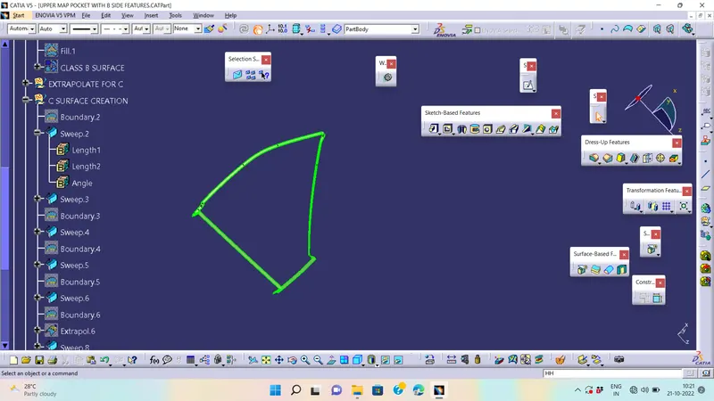
closed Surface Creation :-
- Trim the obtained surface with Class B surface.
- Make Slight Adjustments by extrapolating small values and trimming to obtain a final Enclosed Surface.
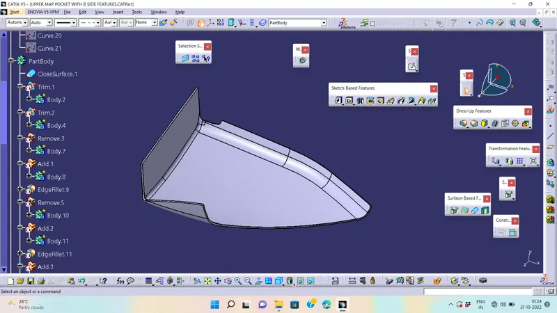
- The final Enclosed Surface Obtained is shown in Figure.
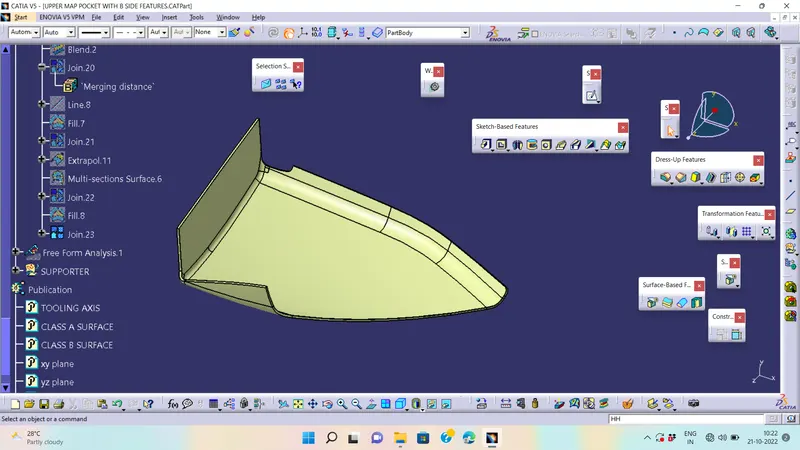
SOLID CONVERTION BY USING CLOSED SURFACE COMMAND
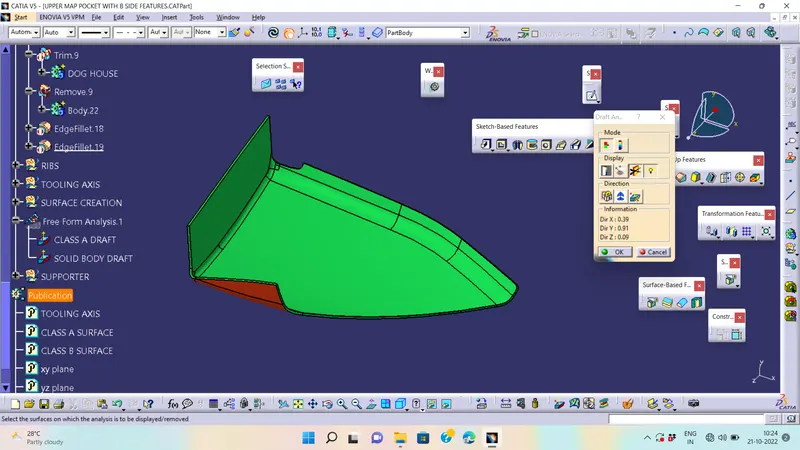
Perform Draft Analysis on Final solid body :-
- Change View Mode Customization to Material mode.
- Go to INSERT---> ANALYSIS---> FEATURE DRAFT ANALYSIS and move the compass to the Main Tooling Axis.
- Change the range to 3°. Apply the settings as shown if Figure.
4.LOWER MAP POCKET:-
- After receiving the Class-A for the connectivity of the surfaces on it.
- Use boundary operation and disassemble.
- Check for discontinuous Surface.
- The check is over if any discontinuities do not arise.
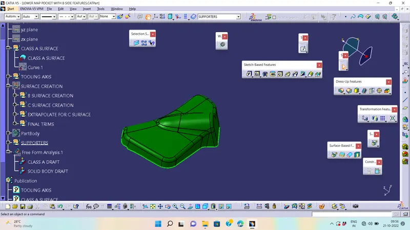
Determine the tooling Axis :-
- Identify faces which can potentially create problems while manufacturing.
- Surfaces at angles along a desired Tooling Axis.
- Create the intersection by using the plane.
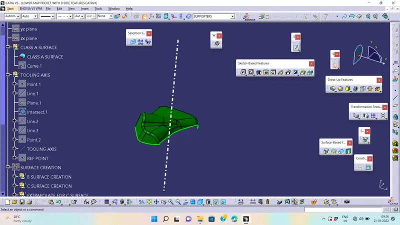
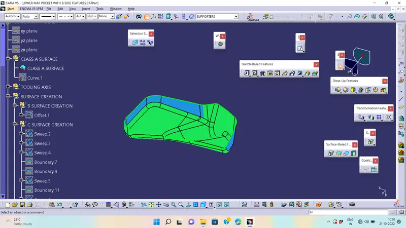
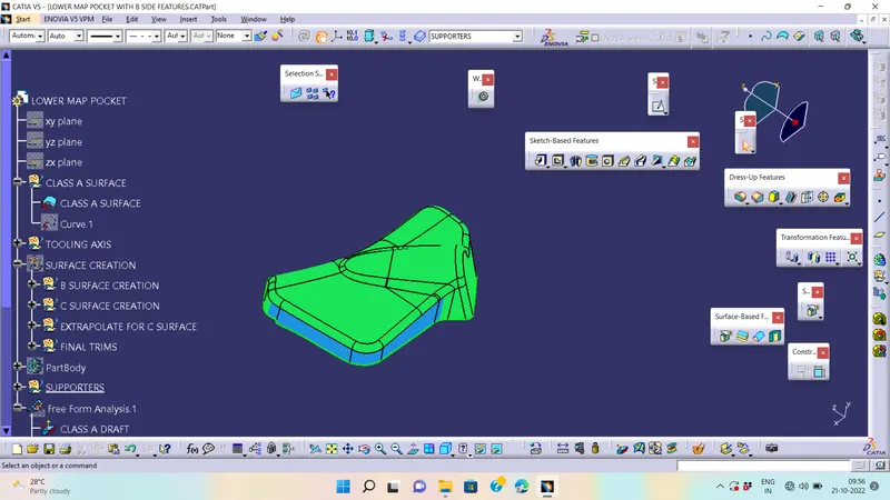
DRAFT ANLYSIS FOR CLASS A:-
- Change View Mode Customization to Material mode.
- Go to INSERT--->ANALYSIS--->FEATURE DRAFT ANALYSIS and move the compass to the moving Axis.
- WE ARE FINDING given A class surface is not clearing draft anlysis inform to styling team
Class-B Surface Creation :-
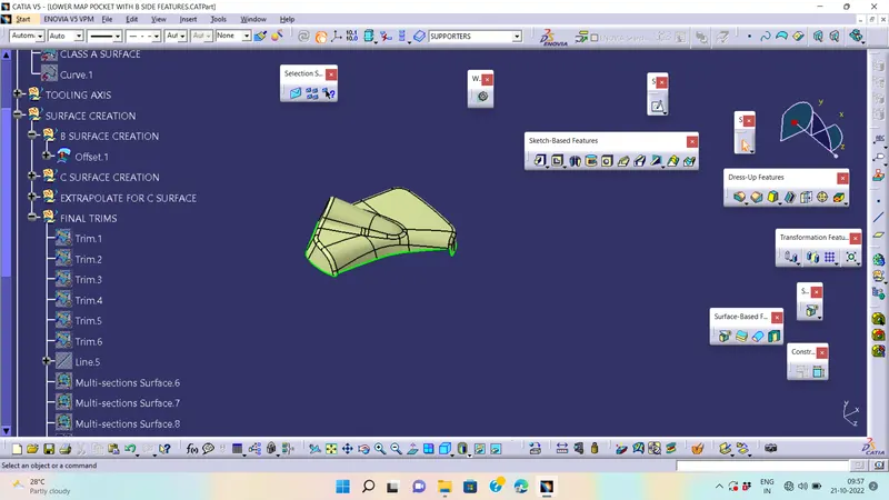
- The creation of class-B surface can be done by smiply offsetting the class-A surface to the required distance and required direction.
Class-C Surface Creation :-
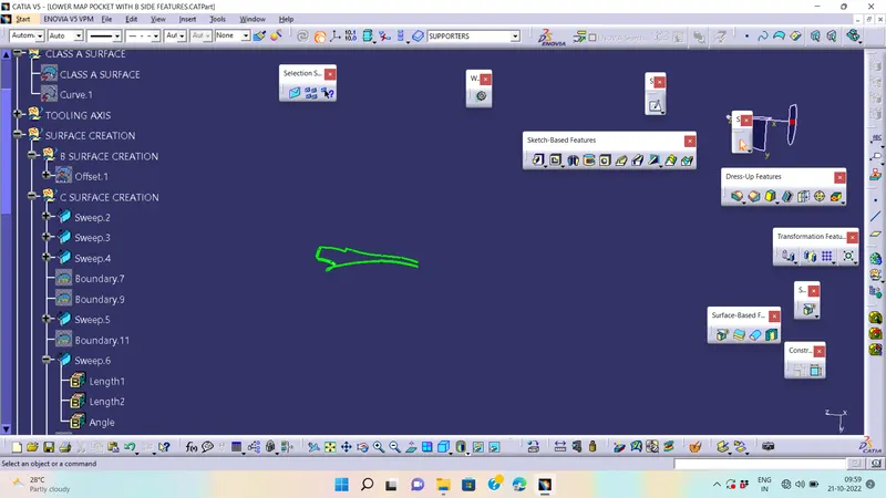
- Extract Class A boundary and convert to Smooth Curve.
- Sweep the curve to the Class A.
- Sweep value should be greater than the Thickness required for part.
- The obtained sweep is shown in Figure.
- Join the Class A Surface with the Class C surface to create a single surface entity.
closed Surface Creation :-
- Trim the obtained surface with Class B surface.
- Make Slight Adjustments by extrapolating small values and trimming to obtain a final Enclosed Surface.
- The final Enclosed Surface Obtained is shown in Figure.
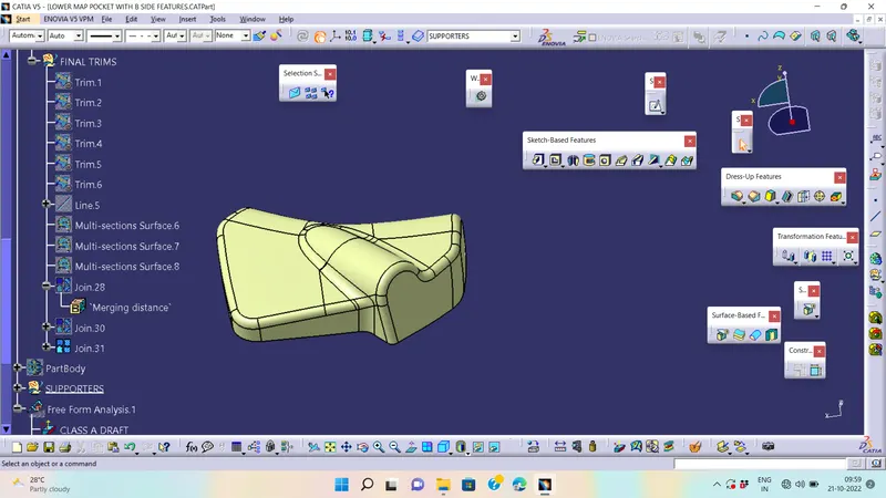
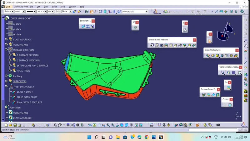
SURFACE TO SOLID BY USING CLOSED SURFACE COMMAND

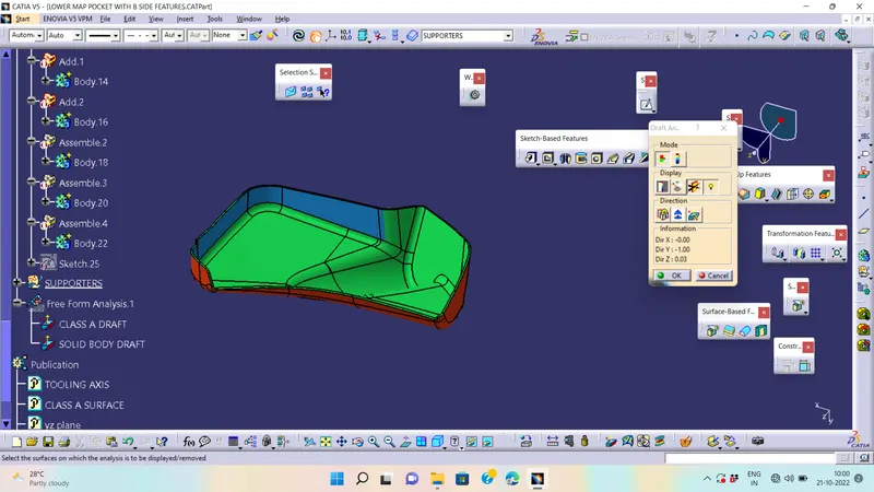
Perform Draft Analysis on Final solid body :-
- Change View Mode Customization to Material mode.
- Go to INSERT---> ANALYSIS---> FEATURE DRAFT ANALYSIS and move the compass to the Main Tooling Axis.
- Change the range to 3°. Apply the settings as shown if Figure.
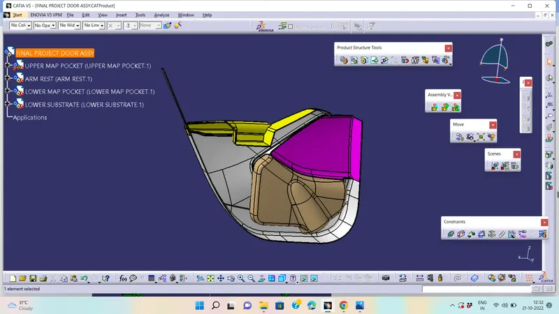
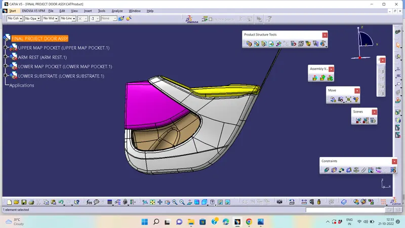
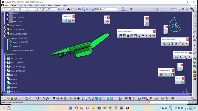
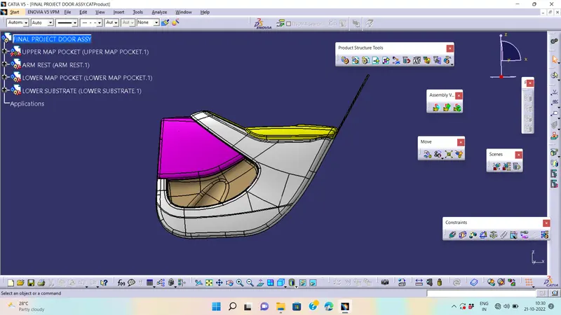
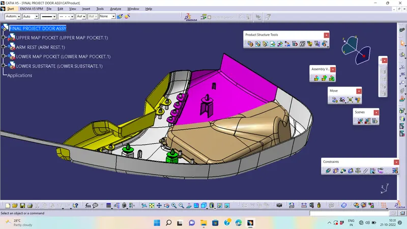
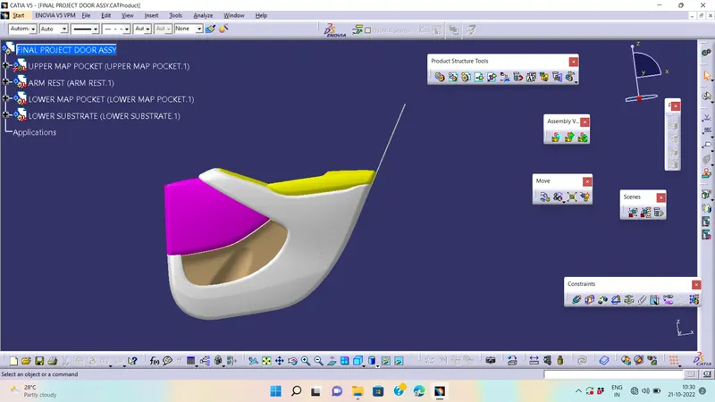
FINAL ASSEMBLY:-
PART-2
DESIGN B SIDE FEATURES:-
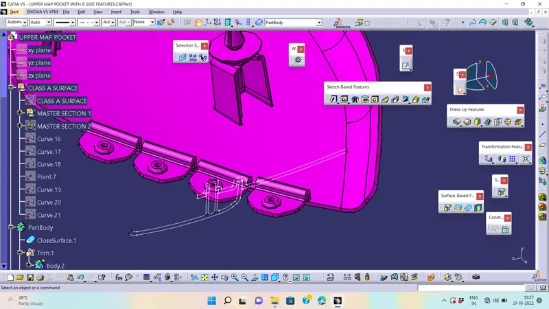
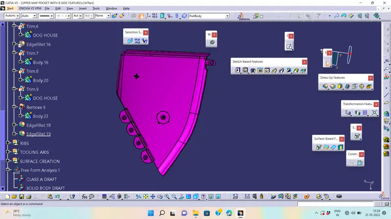
- First Create Flanges where ever required on the part bodies. The purpose of flange is to accomodate heatstakes on the part bodies.
- After creating the flanges create heat stakes at the places where flanges are present. For the thickness and diameter of the heat stakes refer to the master section which is given in the challenge.
- After creating the heat stakes create ribs on the lower substrate. The main purpose of creating ribs is to support the flange as well as ribs under the application of large pressure and force when the process of melting heat stakes is happening.
FOR CREATING B SIDE FEATURES FOLLOWS MASTER SECTION
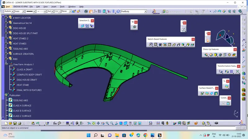
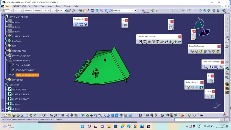
DOG HOUSE:-
- Extract the surface that we going to create a dog house
- Insert a axis system. use positioned and draw a dog house sketch
- Sweep the sketch to 1.5 degree on the direction of main tooling axis
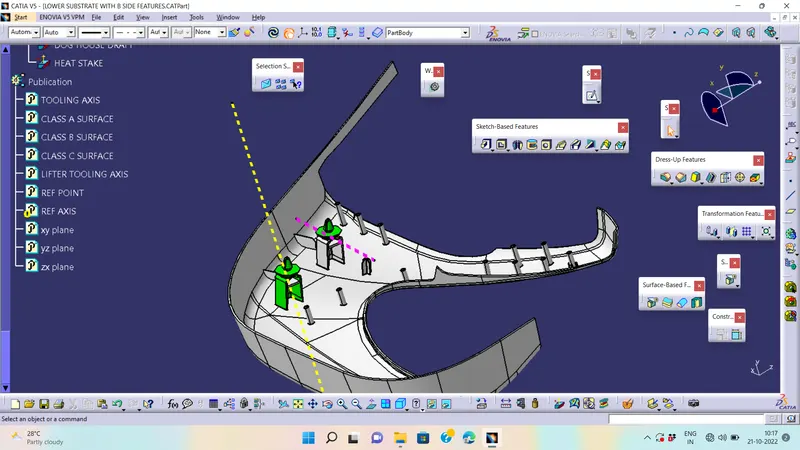
- Add thickness to the above sketch of 2.5mm by using thicken surface
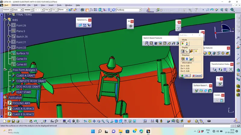
Dog house rule
B=4mm
t=2.5mm
C=0.4 * t=1mm
- Extract the sweep and offset to b=4mm and c=1mm on all directions like the below
4 WAY LOCATOR:-
Perform Draft Analysis on Final solid body :-
- Change View Mode Customization to Material mode.
- Go to INSERT---> ANALYSIS---> FEATURE DRAFT ANALYSIS and move the compass to the Main Tooling Axis.
- Change the range to 3°. Apply the settings as shown if Figure.
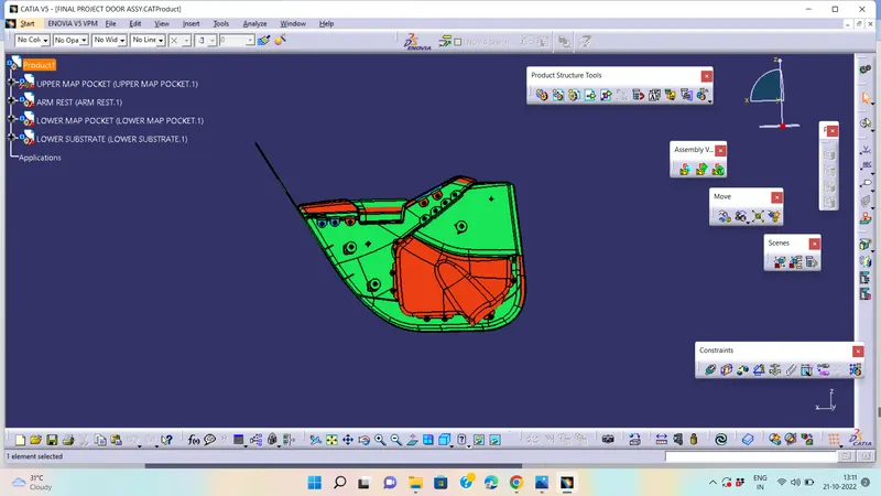
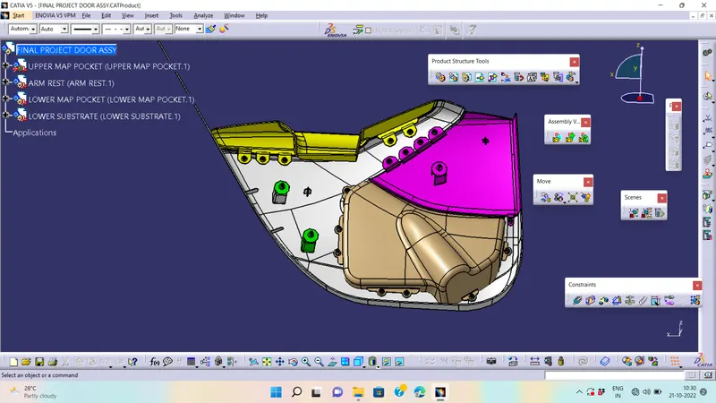
FINAL ASSEMBLY OF PART1 & PART2 PROCEDURE'S
CONCLUSION :-
Class-B and Class-C Surfaces are created to the given Class-A surfaces. The design of B-side features is done and they are assembled successfully. A detailed report has been prepared and all the part bodies and assembly has been attached to the challenges successfully.