Week 11 - Final project
AIM
To create a door interior part from the inputs of class A surface along with the master section by following the design rules followed in tier 1 and OEM industries in CATIA v5
SOFTWARE USED
CATIA V5
OBJECTIVES
- Create a sketch by using the Positioned sketch
- All the sketches are should be Iso-Constrained
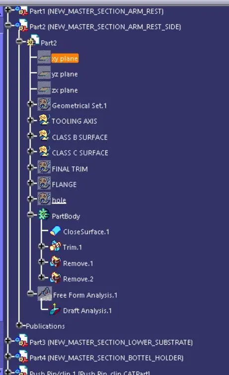
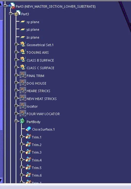
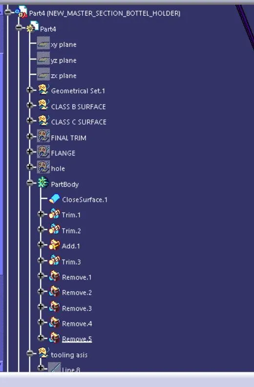
- Ensured Proper Tree Structure
- Geometrical sets should have a proper name based on the sketches present inside of it
- Create thickened part using the master section for reference
- Create the mounting features as per design guidelines in the industry and with master sections
- Creating Draft analysis & Tooling analysis
- Creation of parting lines and checking tooling feasibility
INPUT OF CLASS A SURFACE
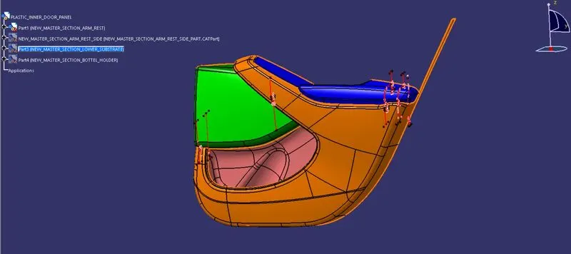
Since the input class A surface is containing four different parts(class A). So class b and c for all the surface has been created in a separate part. Also performing draft analysis and tooling axis separately. finally, all the surfaces have assembled together into one product
CREATION OF TOOLING AXIS – LOWER SUBSTRATE
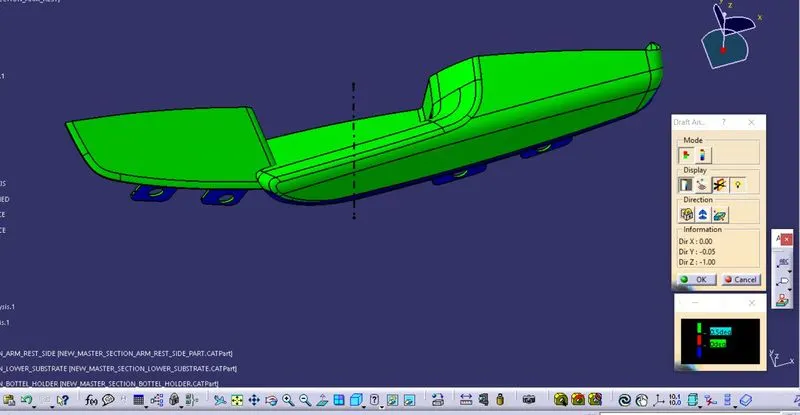
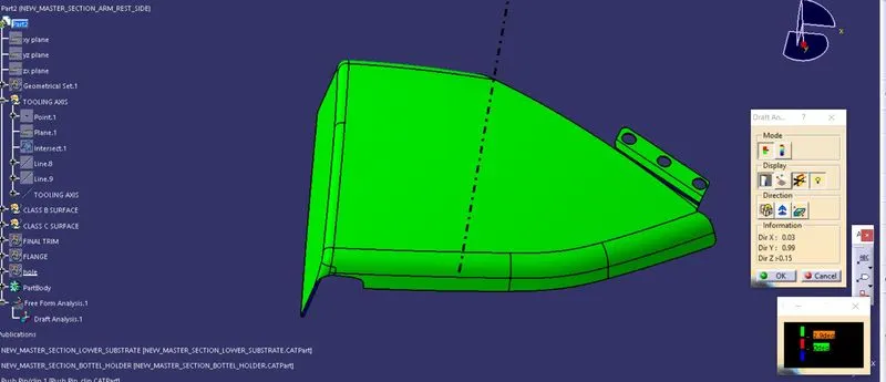
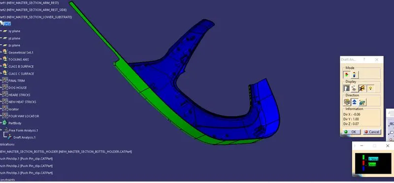
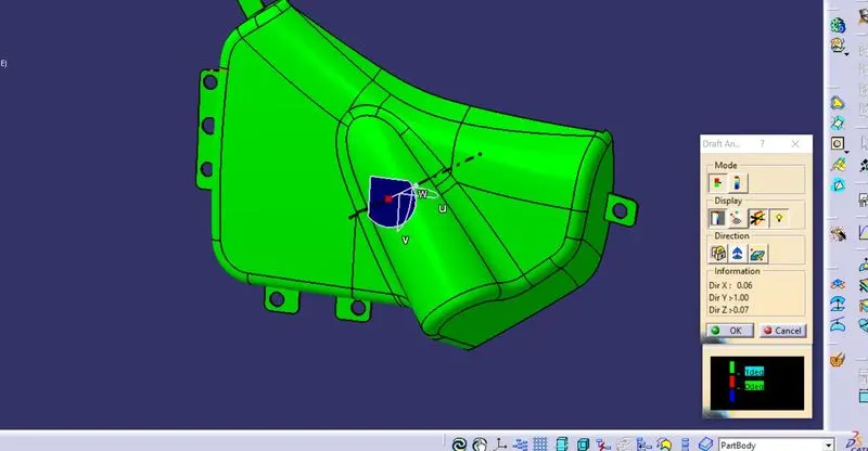
DRAFT ANALYSIS
Draft analysis in CATIA is a command that is used to detect if the part you drafted will be easily removed from the mold. it is performed based on color ranges identifying zones on the analyzed element.
Most industries is using a minimum draft angle is 3 degrees
TOOLING AXIS WAS CREATED WITH THE REFERENCE TO CLASS A SURFACE
The Tooling Direction is basically the direction that the mold pulls apart. The mold is built in two separate pieces, basically. You have a Cavity side and you have the Core side. The Core pulls apart from the Cavity, the Dye line or the Tooling Direction.
NEW_MASTER_SECTION_ARM_REST
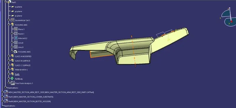
NEW_MASTER_SECTION_ARM_REST_SIDE
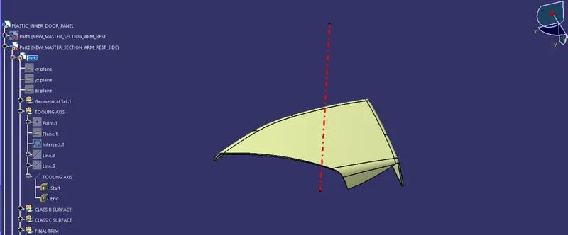
NEW_MASTER_SECTION_LOWER_SUBSTRATE

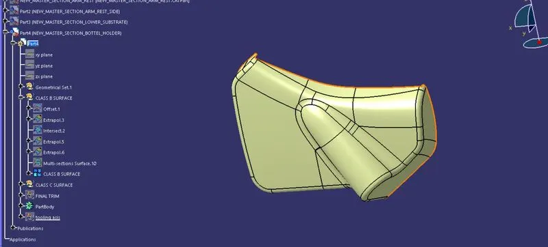
NEW_MASTER_SECTION_BOTTEL_HOLDER
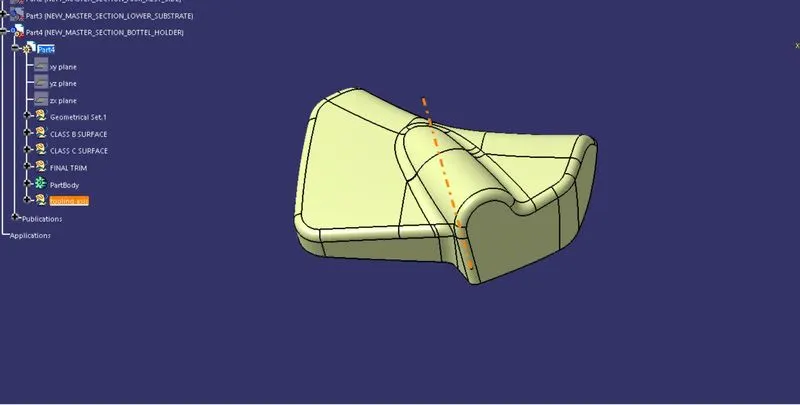
Creation of Class B:
- Now for Class B creation, we have extracted surfaces from Class A and untrimmed them to obtain the original parent surface.
- These surfaces are then offset to the required thickness.
- After offsetting, all the surfaces are trimmed into the required shape.
- Required fillets are given to the surfaces.
NEW_MASTER_SECTION_ARM_REST
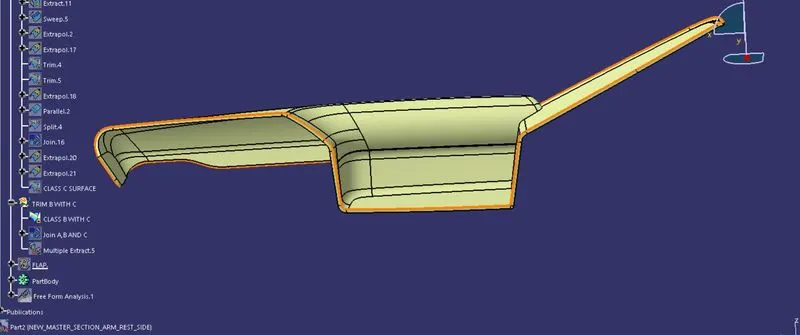
NEW_MASTER_SECTION_ARM_REST_SIDE
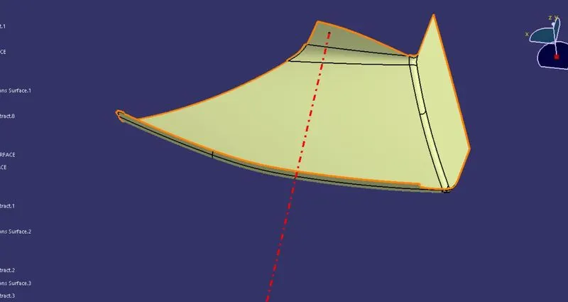
NEW_MASTER_SECTION_LOWER_SUBSTRATE
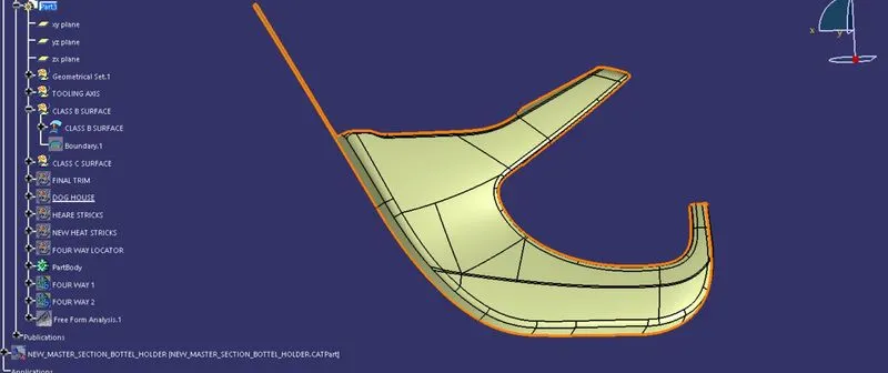
NEW_MASTER_SECTION_BOTTEL_HOLDER
C class surface :
Class C Surface has swept along the boundary CLASS A surface with respect to the tooling axis direction with a draft angle of a maximum 3 degrees and minimum of 0.5 degrees.
NEW_MASTER_SECTION_ARM_REST
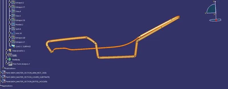
NEW_MASTER_SECTION_ARM_REST_SIDE
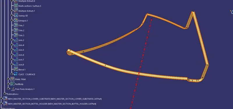
NEW_MASTER_SECTION_LOWER_SUBSTRATE
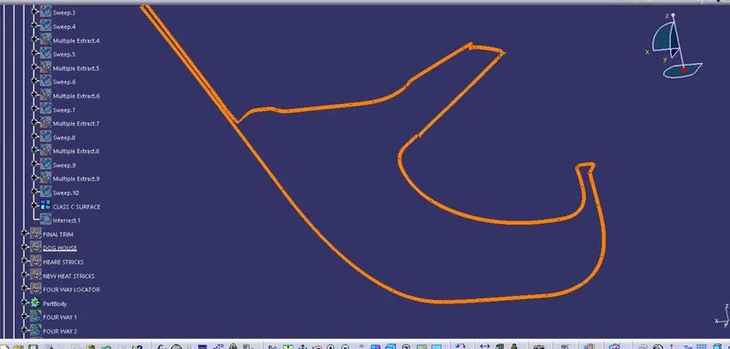
NEW_MASTER_SECTION_BOTTEL_HOLDER
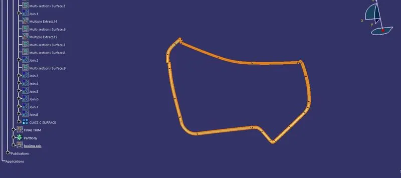
Create the dog house and top cut considering the design rules mentioned in the video for the door applique.
- To Create the pillar design with the master section with Engineering Features Component from the given Class-A surface.
- To Create the tooling axis for the given Class-A Surface meeting the requirements of the draft angle.
- Creating class B surface by using offset command.
- Fixing class B offset surface making into a single part.
- to create a class C surface with a class A surface as a reference.
- To perform the Draft analysis on the model.
- creating a tooling axis and checking for draft analysis if the feature is clearing or not.
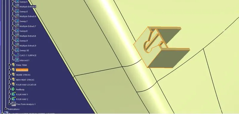
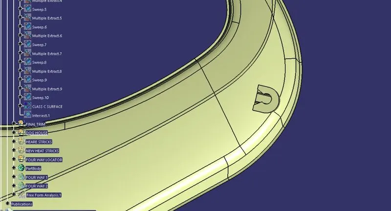
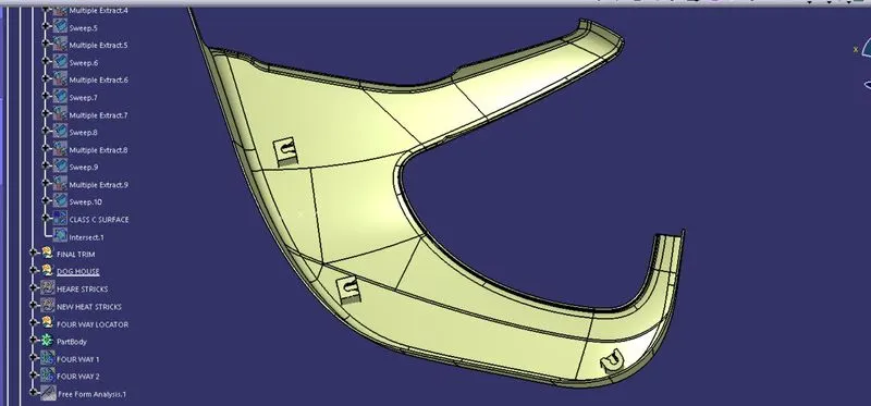
Dog house rule
B=4mm
t=2.5mm
C=0.4 * t=1mm
- Extract the sweep and offset to b=4mm and c=1mm on all directions like the below
HEAT STAKES
Heatstakes is known as thermoplastic staking is the process of joining two dissimilar metals together
- Extract the surface that we going to create heat stake
- Use positiioned sketch and draw a heat stakes sketch
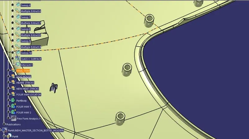
- Use pad commands for the sketch to till we required
- Draft the stakes minimum of 0.5 degree
- Add fillet 0.5mm o all faces
- Assemble the heat stake to lower subtrate solid
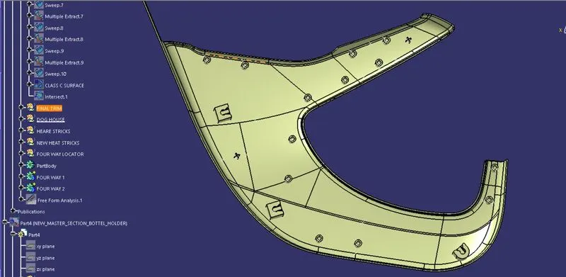
- Maintain a 50mm minimum between two heat stakes
- Translate the heat stakes to wherever we need
- Trim all heat stakes with lower substrate solid
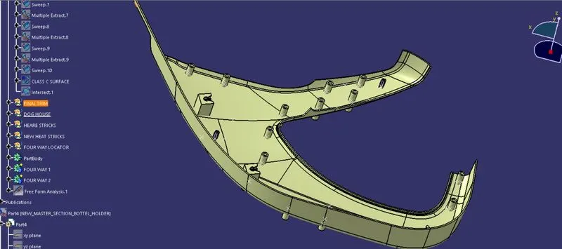
LOCATOR
- Extract the surface that we going to create a locator
- Use positioned sketch and draw a locator sketch
- Use pad commands for the sketch to till we are required
- Draft the locator for a minimum of 0.5 degree
- Add fillet 0.5mm o all faces
- Assemble the locator to lower substrate solid
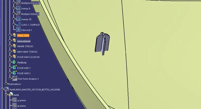
TWO FOUR WAY CREATED AND SHOWN
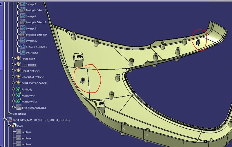
FLANGE
Create a flange for attachment of heatstakes and locators at lower substrate
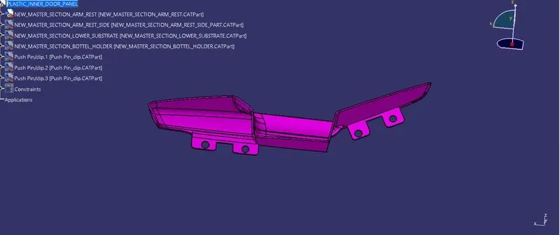
NEW_MASTER_SECTION_ARM_REST
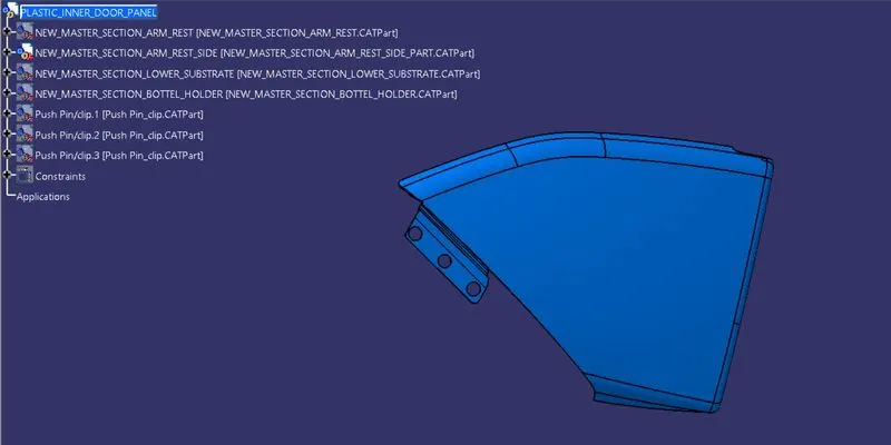
NEW_MASTER_SECTION_ARM_REST_SIDE
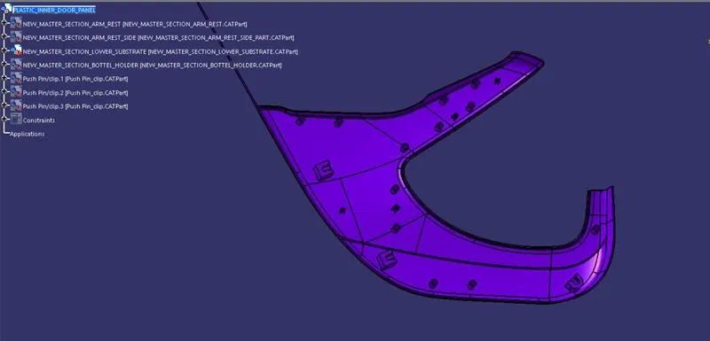
NEW_MASTER_SECTION_LOWER_SUBSTRATE
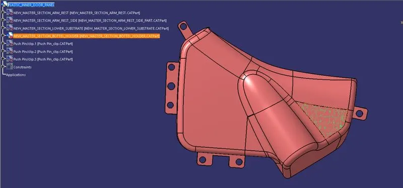
NEW_MASTER_SECTION_BOTTEL_HOLDER
Draft analysis :
The Draft Analysis allows the user to easily analyze a part for a proper draft angle. A Draft Angle describes the amount of taper for molded or cast parts perpendicular to the parting line. Find the Draft Analysis in the Tools tab. Draft Analysis is applicable for 3D part models.
The draft analysis button within CATIA V5 will help you quickly gather the draft angle on multiple surfaces without the need for tedious manual measurements. Here is a quick rundown of how the icon works when you have a given die direction.
NEW_MASTER_SECTION_ARM_REST
NEW_MASTER_SECTION_ARM_REST_SIDE
NEW_MASTER_SECTION_LOWER_SUBSTRATE
NEW_MASTER_SECTION_BOTTEL_HOLDER
PUCH PIN
Puch pin is shown and attached to the dog house.
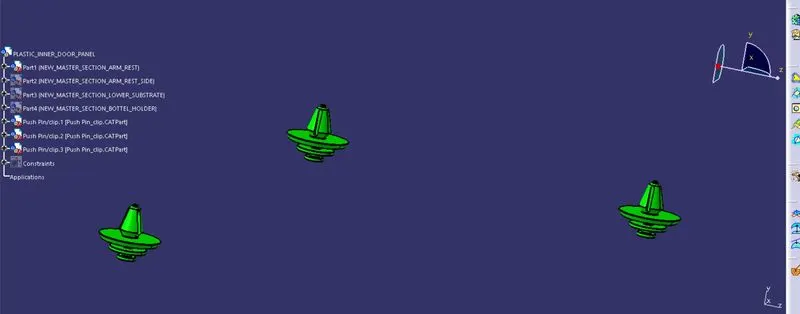
the pin is connected to the dog house and shown below
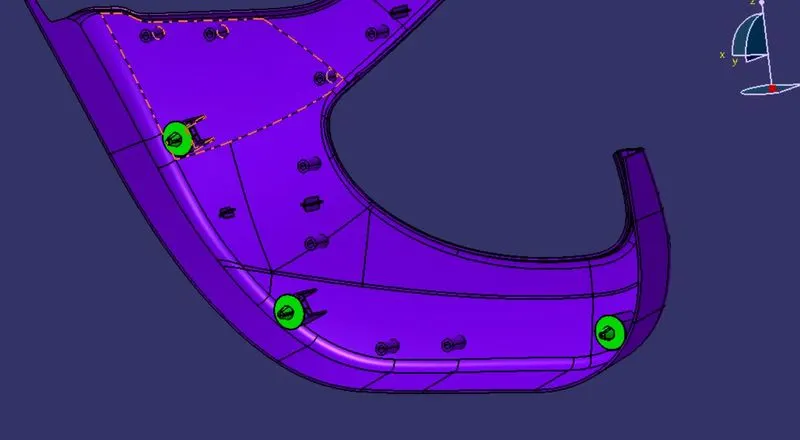
THE COMPLETE PART IS SHOWN BELOW
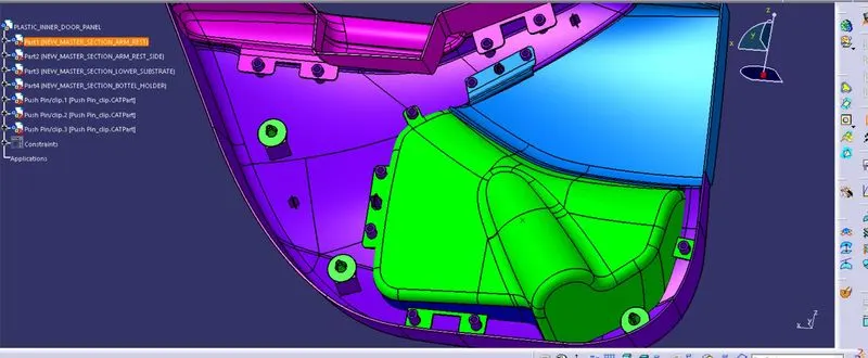
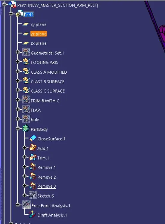
TREE STRUCTURE
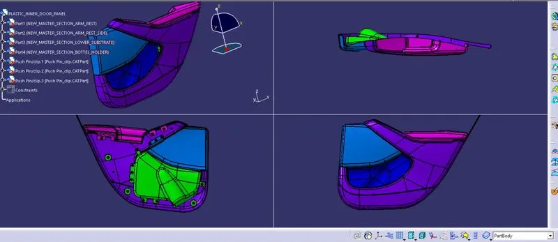
MULTI VIEW IS SHOWN BELOW
Conclusion:
Creation of the car interior door trim is designed using the given class A surface as the input and Class B and C surfaces created with the help of the Class A surface. By using the given master section attachment features I.e. Heat stakes, Flanges, Dog houses and Push Clips are created using the design rules. The draft analysis has been performed to analyze the draft of the component to manufacture easily applying draft to the surface by 3 degrees and 0.5 degrees to the attachment features. With all data and report, we can conclude that draft analysis is very important to design any plastic component to mold the plastic easily. The analysis will verify that all surfaces are favorable for being pulled from a cavity. It may also highlight or give insight to defect areas.