Week 11 - Final project
DOOR TRIM PANEL
OBJECTIVE
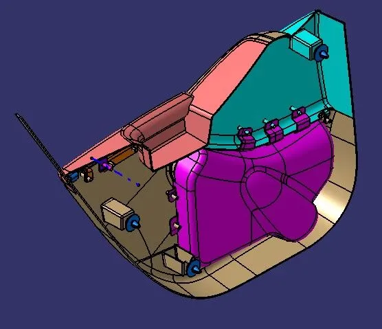
This project objective is to create fully developed solid bodies for all the given door trim components and add the necessary commodities to assemble all the part bodies using CATIA v5.
PROCEDURE
1. CREATING THE SOLID BODY
Door Armrest
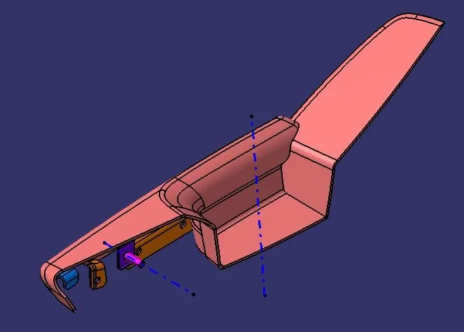
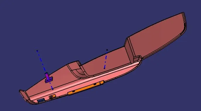
The initial design step is the class-A surface inspection and the tooling direction creation. The initial direction of the class-A surface is to be assumed, and the edges or the surfaces which are likely to be challenging to be produced in this direction are taken by making an intersection. The initial direction is modified accordingly to obtain the tooling direction. Once the tooling direction is done, draft analysis is performed on class-A. The given thickness value directly offsets the A-surface in the master section (2.5mm) to create class-B. Some patches are developed in the B-surface, and these are fixed using the surface commands appropriately. To create the class-C surface, the boundary of class-A is divided into multiple extracts based on the discontinuity, and with the help of the sweep command, the C-surface is produced at the desired angle. The C-surface is trimmed together, and the B-surface is extrapolated to meet these trimmed faces. The necessary surfaces are selected, and a closed surface body is created, which is used to create a solid body.
Class A
Solid Body
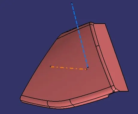
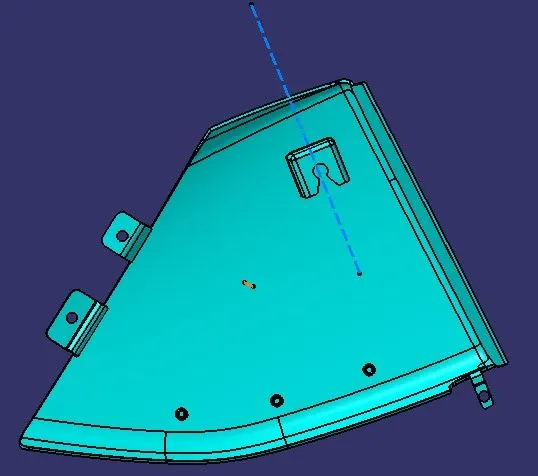
The design methodology to obtain solid models for the other components (map pocket, Bottle holder, and Lower substrate) remains the same as the door armrest.
Map Pocket
Class A
Solid Body
Bottle Holder
Class A
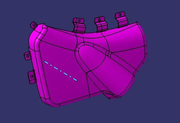
Solid Body
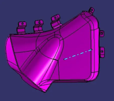
Lower Substrate
Class A
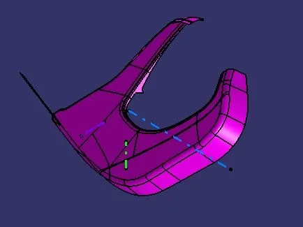
Solid Body
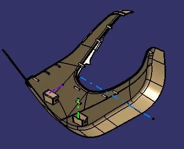
2. CREATING THE ASSEMBLY
Once all the solid bodies are obtained, an assembly is created, and all the parts are added to the assembly using the existing component feature in the Assembly workbench.
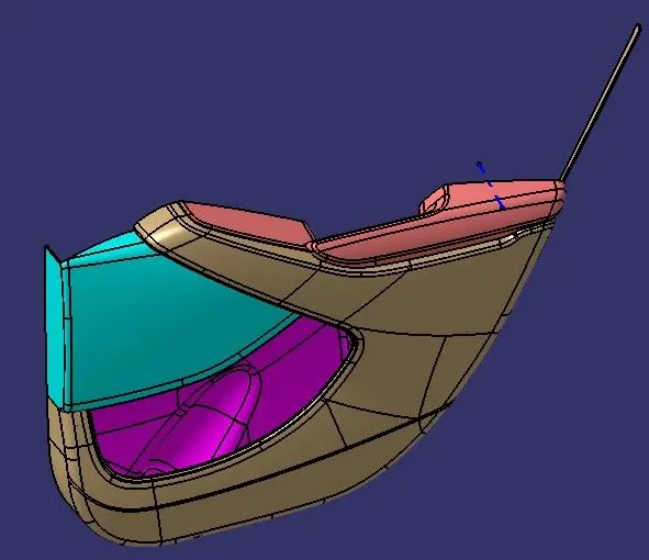
3. CREATING HEAT STAKES
In the master section for this assembly, the heat stakes are given at some only locations, but the location of other heat stakes is up to the designer’s interest. So, appropriate location points are marked, and the sketches are created, which are used to obtain the solid heat stake. The inner diameter and the outer diameter are found to be 4.5mm and 7.5mm, respectively (from the master section). The inner and the outer walls of the heat stakes are now drafted by 0.5 degrees with respect to the main tooling direction. All heat stakes are joined to the main bodies using the Boolean operations, and finally, all the edges are filleted by 0.25mm radius. The distance between the one heat stake and the other must be greater than or equal to 50mm.
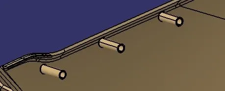
4. CREATING FLANGES
When the heat stakes are created for the assembly purpose on one component, flanges must be created on the counterpart of the assembly to accommodate the heat stakes. The minimum width of a flange must be 30-35mm to avoid the molten heat stake tip overflow after the assembly.
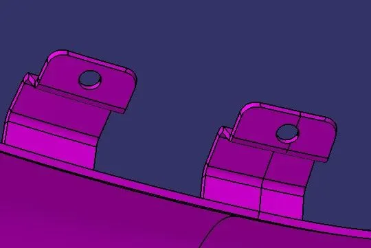
The flanges are created using the sweep command, and the solid part body is obtained by the close surface command in the part workbench. The obtained part body is now split by using the surface of the heat stake as a reference element to obtain the hole, and a minimum of 0.2mm clearance must be provided between the heat stake and the flange. The flanges are now added to the main body using Boolean operations. The minimum fillet radius fillets the necessary edges.
5. CREATING DOG HOUSE
A rectangular sketch is created with appropriate dimensions, and one edge is trimmed off. This sketch is now extruded using the sweep command at an angle of 1.5 degrees from the main tooling axis. The top surface is obtained by offsetting the base surface about the required height and extrapolating to meet the side walls. The top and the side walls are joined together using the trim option. A solid body of 2mm is created using thickness command, and the extra front portion is trimmed off using split command and offset surface.
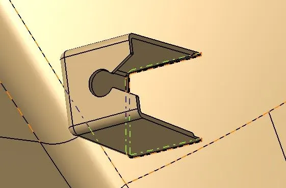
A portion of the dog house needs to be trimmed at the bottom to avoid the sink marks. C value for a dog house is known to be 40 percent of the nominal wall thickness (in this case, it is 1mm), and B value lies between 3 to 6mm depending on the other dimensions (in this case, it is taken as 5.5mm). Required surfaces are offset by B and C values and trimmed to get a surface used to split the solid body. The dog house also needs to be drafted in the side core tooling axis; this aside core tooling axis is created, and a draft of 0.5 degrees is provided in this direction. The inner edges of the walls are 1mm, whereas the outer edges are filleted by 3mm (to maintain uniform thickness). Minimum fillet values are provided for the rest of the edges. Dog houses are added to the main bodies using Boolean operations.
6. PERFORMING DRAFT ANALYSIS
1. Door armrest
In main tooling direction:
CLASS-A surface
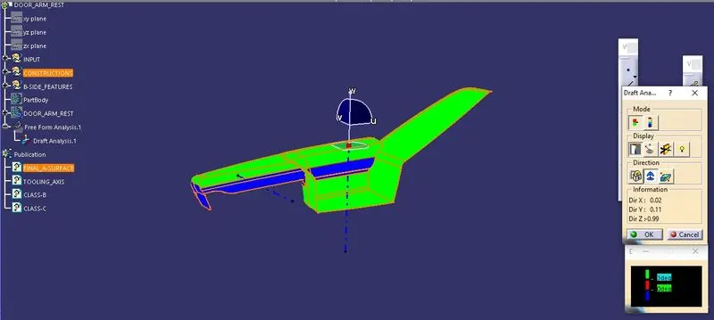
Solid body
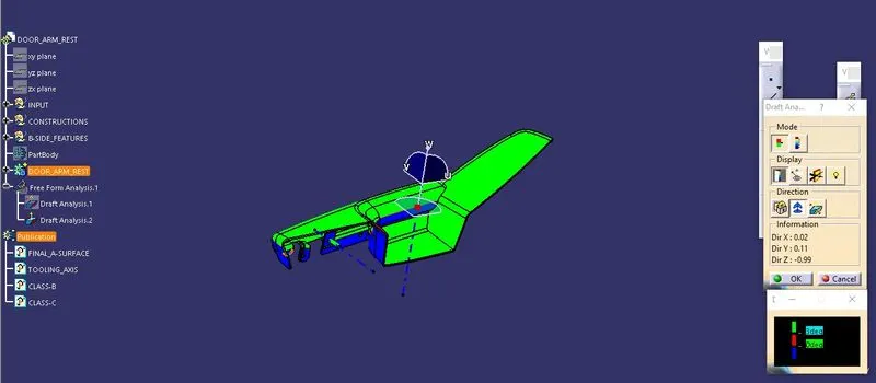
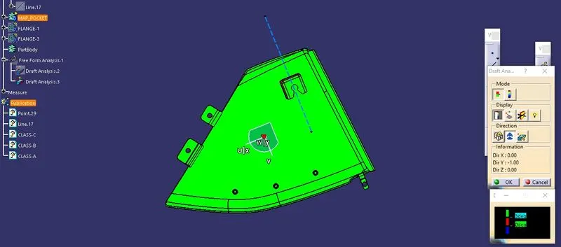
2.Map Pocket
In main tooling direction:
CLASS-A surface
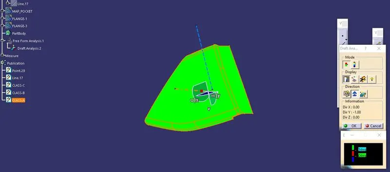
Solid body
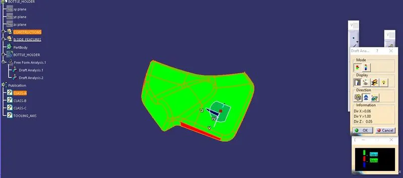
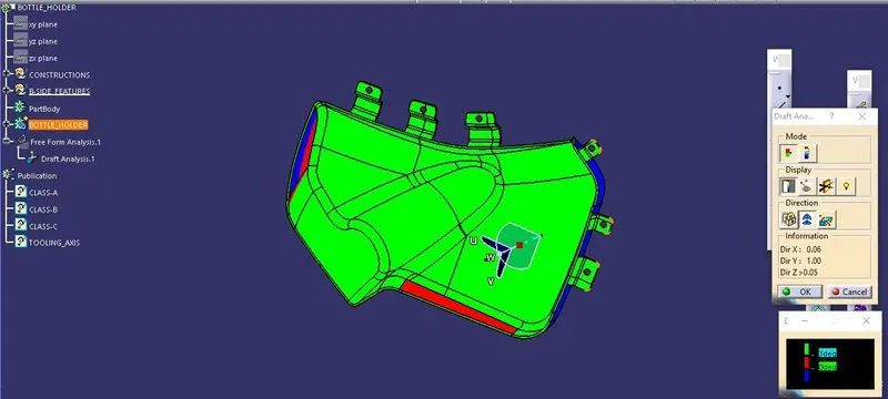
3.Bottle Holder
In main tooling direction:
CLASS-A surface
Solid body
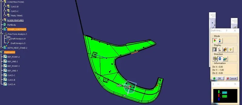
4.Lower Substrate
In main tooling direction:
CLASS-A surface
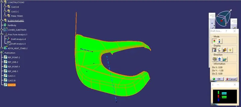
Solid body
Assembly