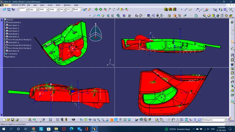
Week 11 - Final project
AIM- To develop a Door Trim panel with Engineering features from given class A Surfaces and Master section
INTRODUCTION-
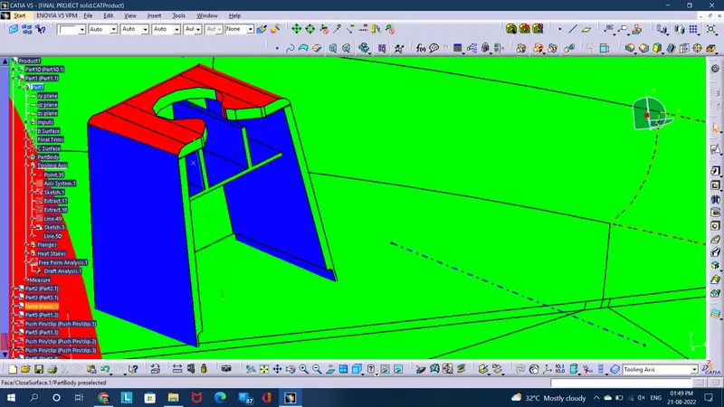
Draft Analysis is performed virtually in order to check the draft angle of the designed part for smooth ejection processes from the mold, when manufactured in the real environment. It performs the analysis on the basis of colors' ranges that dignifies and differentiate the surfaces through colors on the basis of their angles.
Tooling Axis is done in order to find the easiest possible direction of the part ejection from the mold, when manufactured in the real environment. For eg.- A part with holes can be easily ejected along the direction normal to it, hence tooling axis is taken normal to holes.
PART 1-
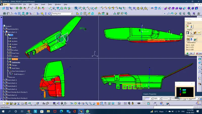
Tooling Axis Creation-
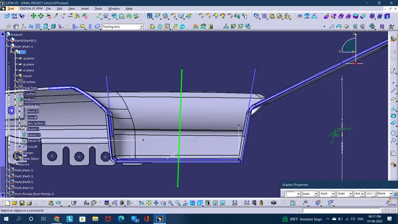
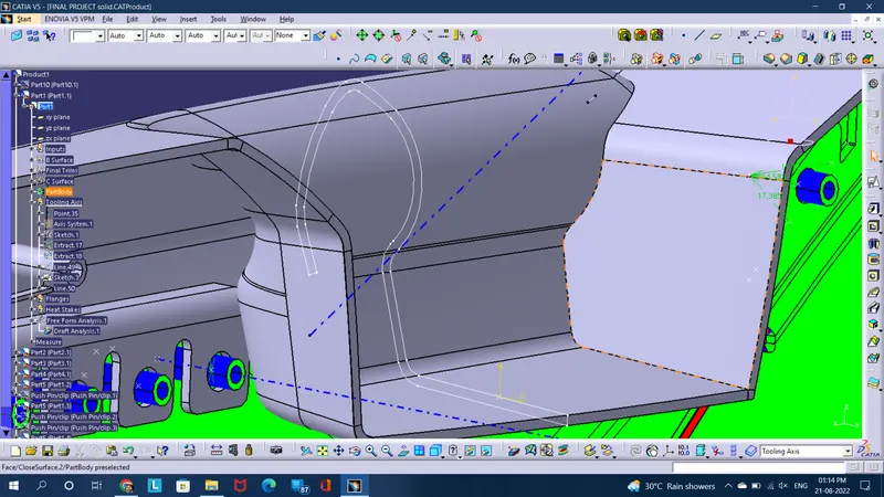
- Initially a supporting axis was created through bisection method from the 2 side lines extracted by intersection method (as given below). Then again 2nd scetch was extracted through intersection method from half body and from which the main tooling axis was created at 3 degrees tangent to the most inside curved part (given below)
PART 2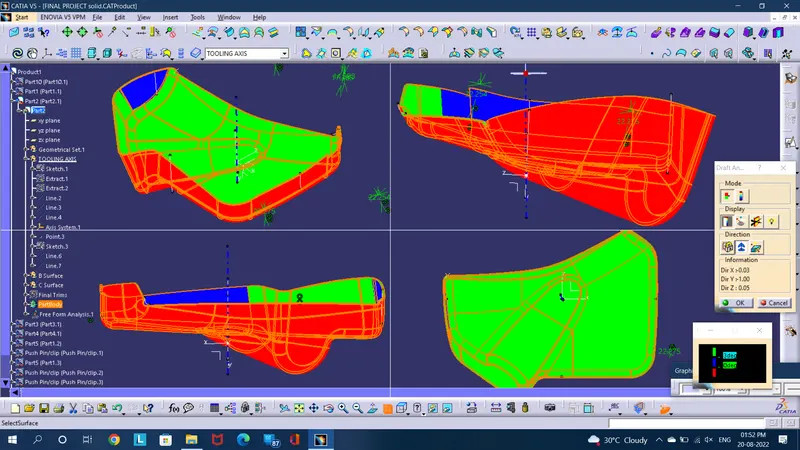
Tooling Axis creation-
- Since it is cleared through the given class A surface that its main tooling axis will lie perpendicular to the bottom surface due to smooth ejection when manufactured and it isn't needed to apply bisecting method through the side walls. So (here) a point is needed to be taken at mid of surface then through point a line will be extended which will be the Main Tooling axis.
PART 3
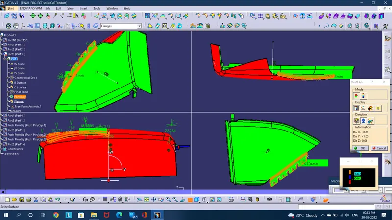
Tooling Axis creation-
- Since it is cleared through the given class A surface that its main tooling axis will lie perpendicular to the bottom surface due to smooth ejection when manufactured and it isn't needed to apply bisecting method through the side walls. So (here) a point is needed to be taken at mid of surface then through point a line will be extended which will be the Main Tooling axis.
PART 4
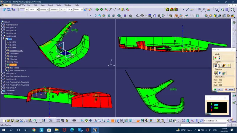
Tooling Axis creation-
- Since it is cleared through the given class A surface that its main tooling axis will lie perpendicular to the bottom surface due to smooth ejection when manufactured and it isn't needed to apply bisecting method through the side walls. So (here) a point is needed to be taken parallel to the Screw bosses through point, a line will be extended which will be the Main Tooling axis.
DOG HOUSE PART 5-
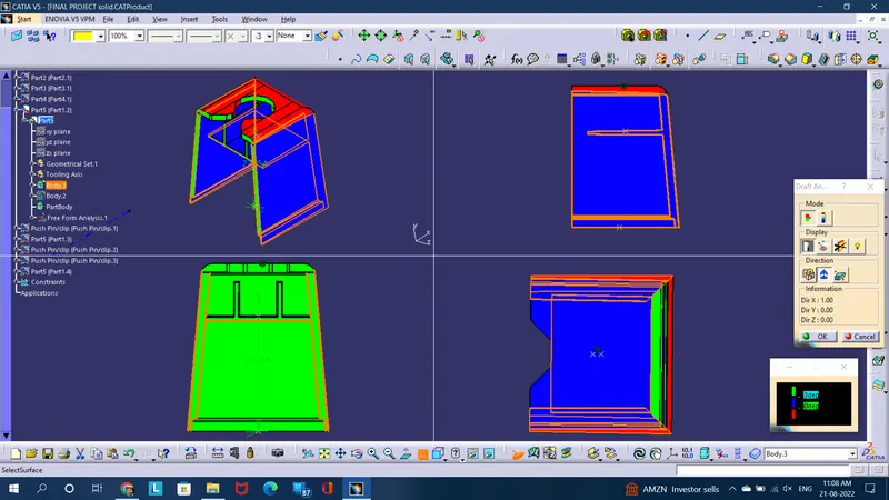
Tooling Axis creation-
- So (here) a point was taken at mid of surface then through point a line was extended parallel to the direction of the pad as given below.
FINAL COMPLETE ASSEMBLY-