Week 11 - Final project
Aim:
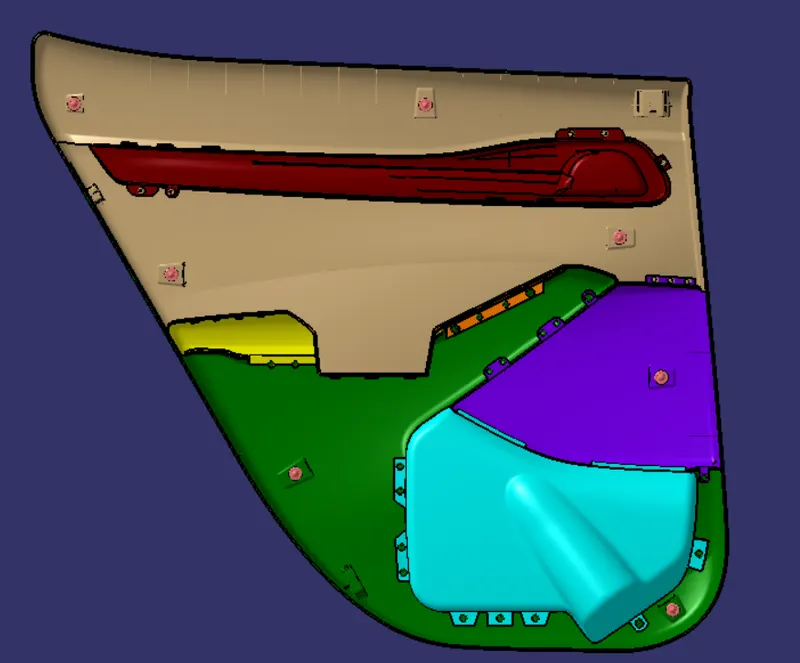
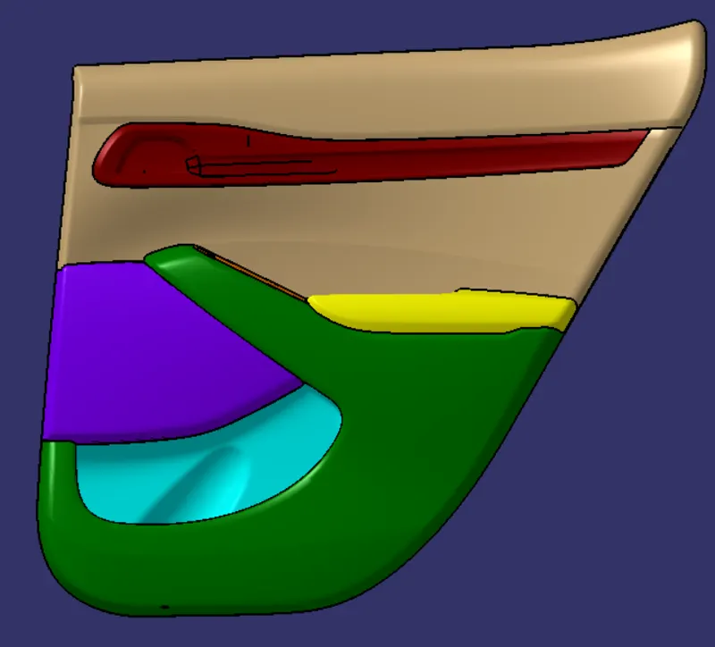
- To create a Door Trim Panel with class A,B,C surface along with Heat stakes,Dog House,Snap fits and push clips.
Tools Used:
- Line
- Circle
- Trim
- Extrude
- Translation
- Extrapolate
- Thick Surface
- Split
- Edge fillet
- Chamfer
- Offset
- Multi-extract surface
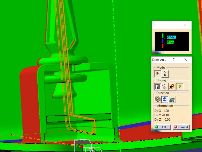
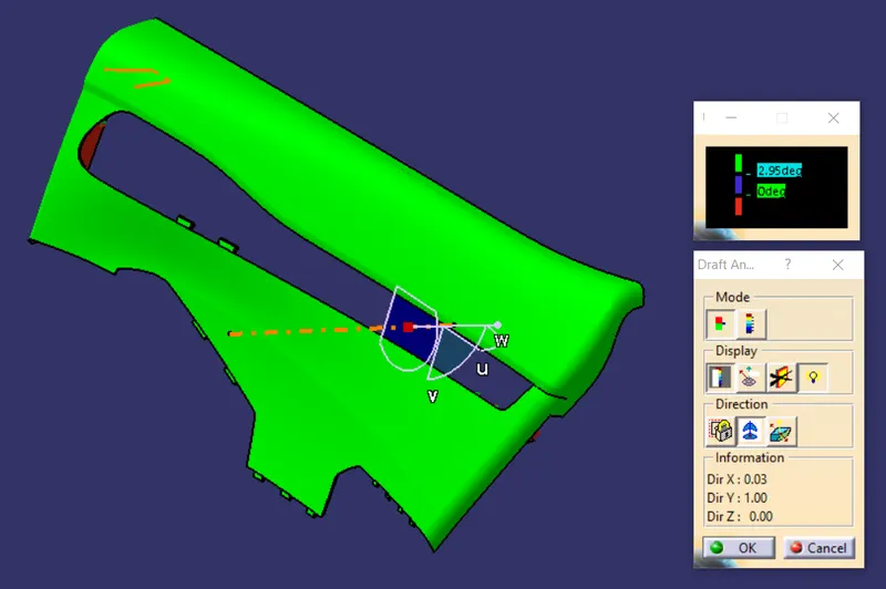
- Draft Analysis
OBJECTIVE:
1) Product Life Cycle:
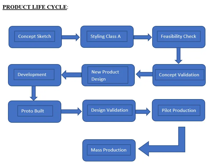
Step 01: (Concept sketch): It is a way of approaching as a quick and simple way of exploring initial ideas for designs.
Step 02: (Styling class A): It is a surface where the concept sketch of the outer body is made with an boundry which has curves,tangency lines,etc.This Styling Class A can be made in Autodesk Alias software.
Step 03: (Feasibility check): In this check need to describe the product basics like scope,boundries,approaches,etc.
Step 04: (Concept Validation):The measurability of the product and the analysis of the results become more accurate if the concept that is being validated can be compared to other products, e.g. similar products from competitors.
Step 05: (New Product design):This stage need to improve the product by getting the feedbacks on the market and providing the needs to the customer satisfaction with new design methodology For E.g) In 90s cars the manual glass adjuster was used now in update we use electric powered glass adjuster.
Step 06: (Development): In this stage the product development is made with proper validations and terms on it.
Step 07: (Proto Built): It is an experimental process were ideas are converted into tangible forms from paper to digital or in clay form to make it visualized.
Step 08: (Design validation): In this stage the design is get validated with dimensions and some calculation factors for further production process.
Step 09: (Pilot production): In this stage the production factors are carried out for E.g) In production of plastics defects will be get corrected it is pre final stage in product life cycle.
Step 10: (Mass Production): This is the final stage,where the design is completely made into a product achieving all terms into it.
2) Stages of the Design Life cycle:
- Concept sketches
- Styling Class A
- Clay modeling
- New Product Design
3) Door Trim Panel:
- The door card will usually match the rest of the vehicle's interior. Door panels were formerly made of cardboard with an upholstered interior finish of Vinyl, leather, cloth, carpet, or other materials for the decorative trim. Modern cars typically have door cards made of plastic, most often using Injection molding, as well as incorporating other decorative materials.
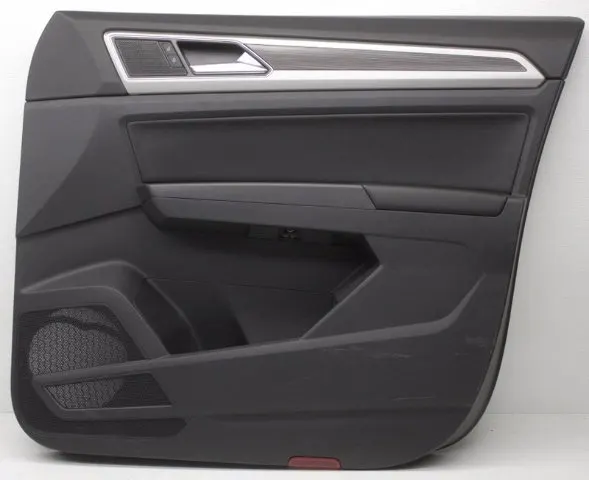
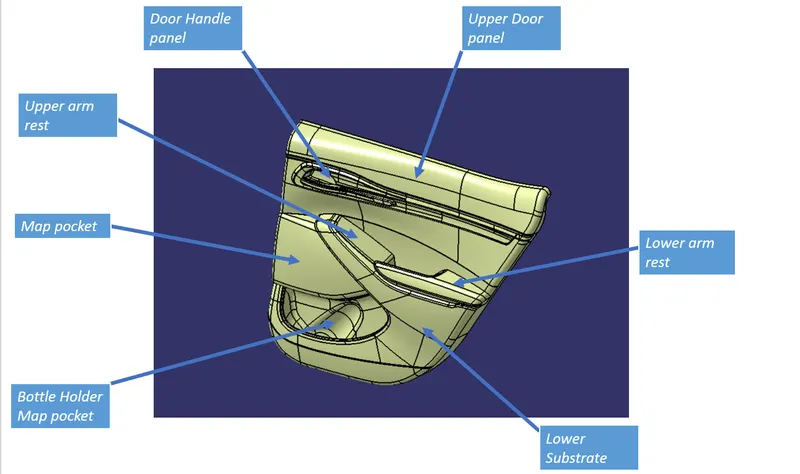
Parts in Door panel:
- Upper Arm Rest
- Lower Arm Rest
- Map Pocket
- Bottle Holder map pocket
- Upper Door panel
- Door Handle Panel
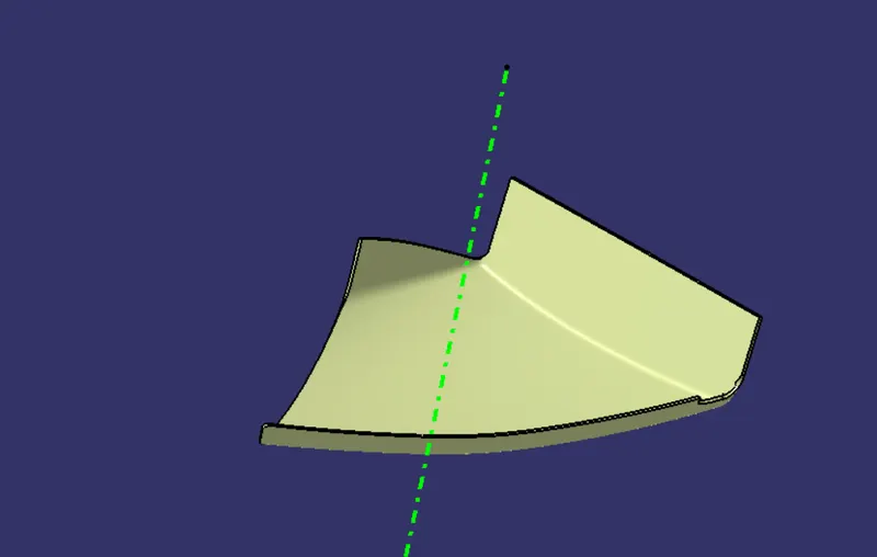
Tooling Axis:
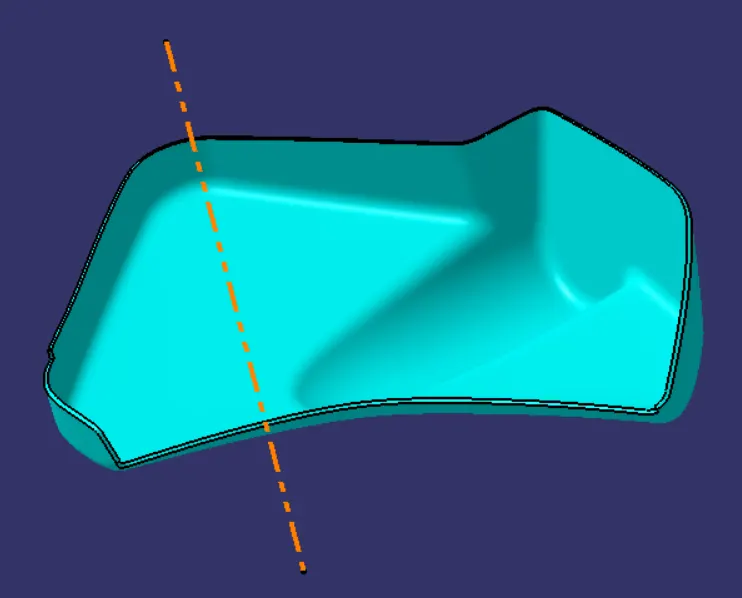
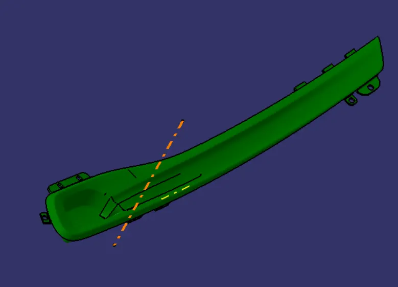
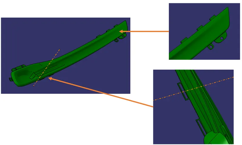
- Tooling axis is represented by a line that describes the tooling direction of the part,so that the part can travel on the axis with achieving the draft angle.
- For creating a tooling axis place a point on the centre of the part and sketch a line through the required axis direction.
- The below fig represent the Tooling axis of the part
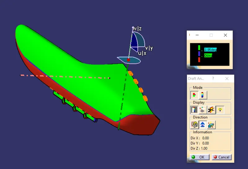
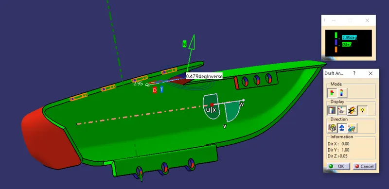
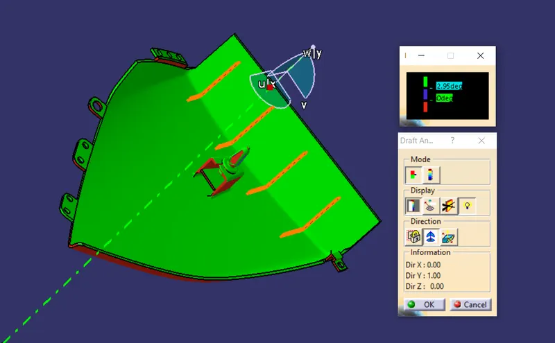
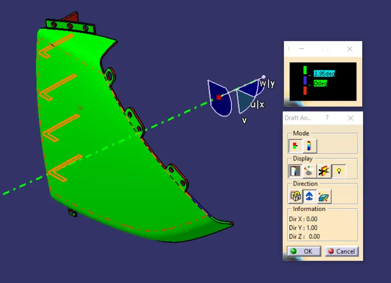
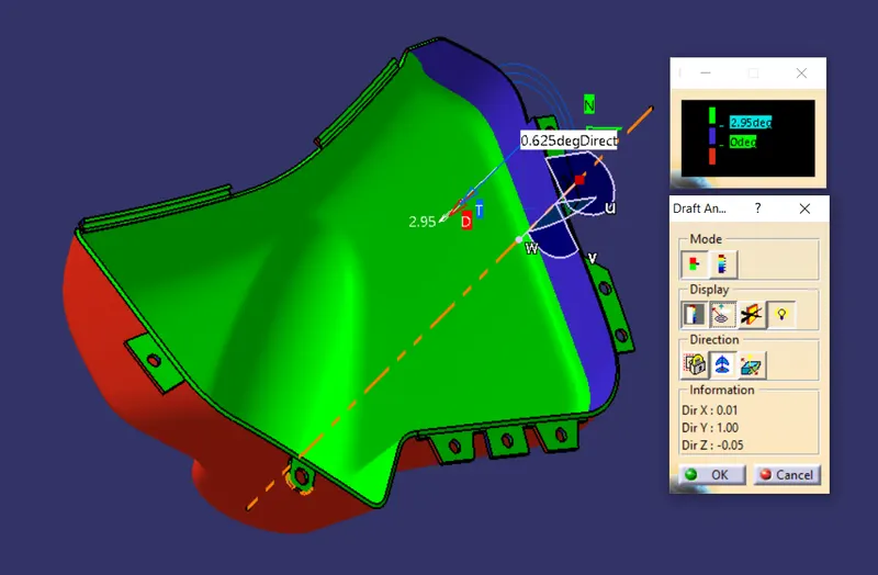
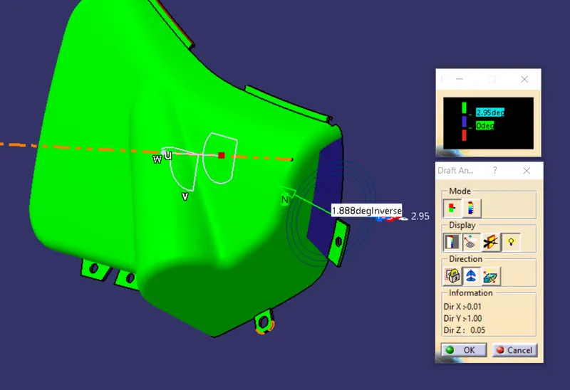
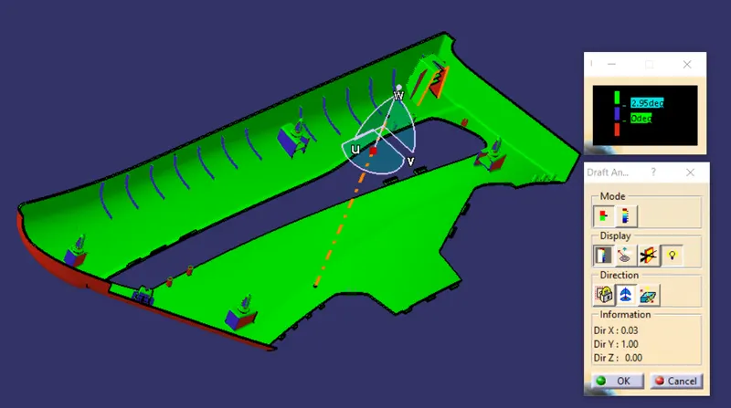
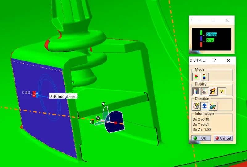
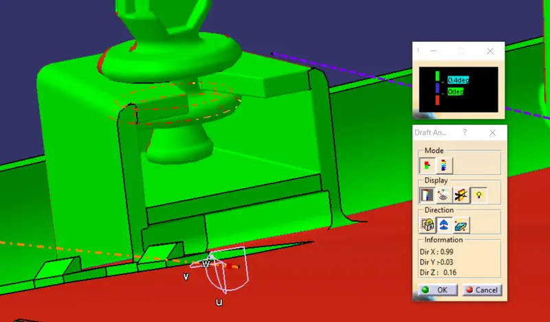
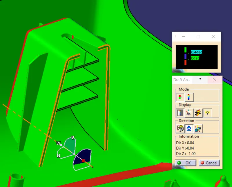
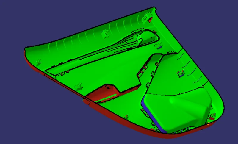
Draft Analysis:
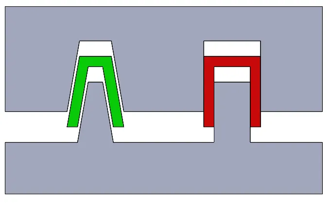
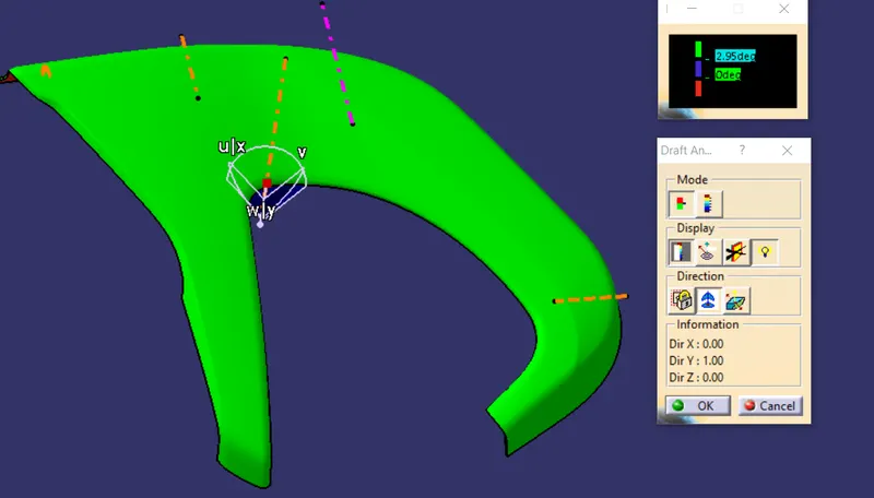
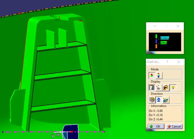
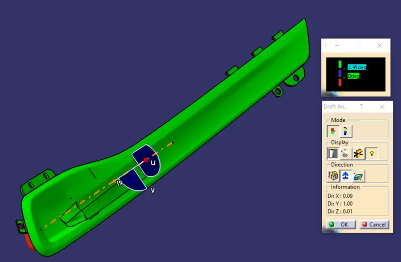
- On Injection molding the parts which are getting ejected will have some defects and very difficult to remove from the cavity, So to make easier and reduce the defects this draft analysis is used.
- The Below pic shows that the parts on the cavity with normal in shape and another is drafted.
- Basically the plastic components should be drafted at 3deg and for a sheetmetal components the draft angle should be 7 deg.
-
Attachment Features:
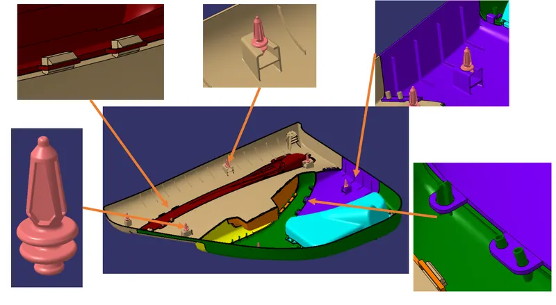
1) 4 Way Locators:
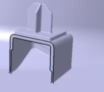
- Locators are used as an guide reference which helps to attach with other plastic parts or steel parts
- It can prevent moment of the part in particular and arrest the degree of freedom on the part in particular axis/
- Below fig shows 4 way locator with dog house.
2) Heat stakes:
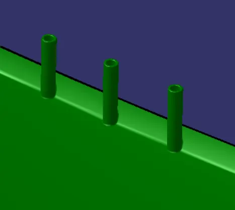
- Heat staking also known as thermoplastic staking is the process of joining two dissimilar materials together. In heat staking we use local heating and cooling to raise the temperature of plastic components and allow plastic reforming to be carried out. This reforming can be used in a wide variety of applications.
- It will be welded together with the part.
3) Dog House:
- It is used as an prevention of plastic defects like shrinkage, breakages which are not visible on outside surface and also it act as an guide.
- For creating Dog House some technical factors are considered.
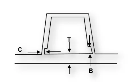
- Wall thickness 'C' should be 40% less than the part thickness 'T'
- Height 'B' should lie b/w 3mm to 6mm.
4) Ribs:
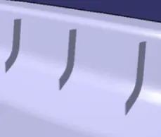
- Ribs are thin wall-like structures that add support and rigidity to injection molded parts.
- They are thinner than primary walls and are used to support these walls and used to replace thick wall sections to avoid sink marks, warp, and voids.
5) Snap Fits:
- These types of fits are used to attach flexible parts,usually plastic, to form the final product by pushing the parts interlocking components together.
6) Push clips:
- A pin that has a cylindrical head and that is easily inserted and withdrawn from the part.

Note:
- Check all the values are in mm
- Maintain all the tools and features available on the panel
- Publish the surface of parts and add various color to the parts for better view and understanding.
- The sketches should be Iso-constrained and save the file with proper name.
Input Model:
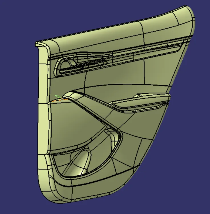
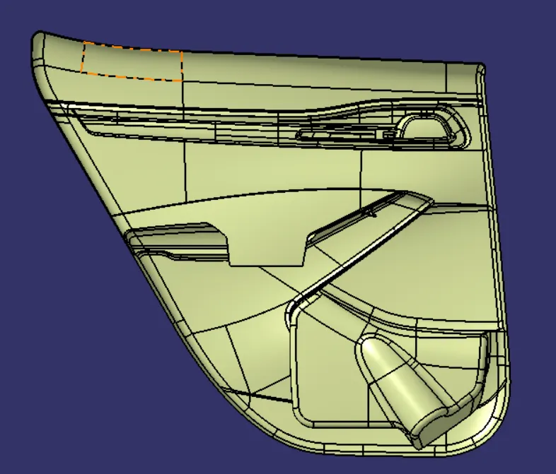
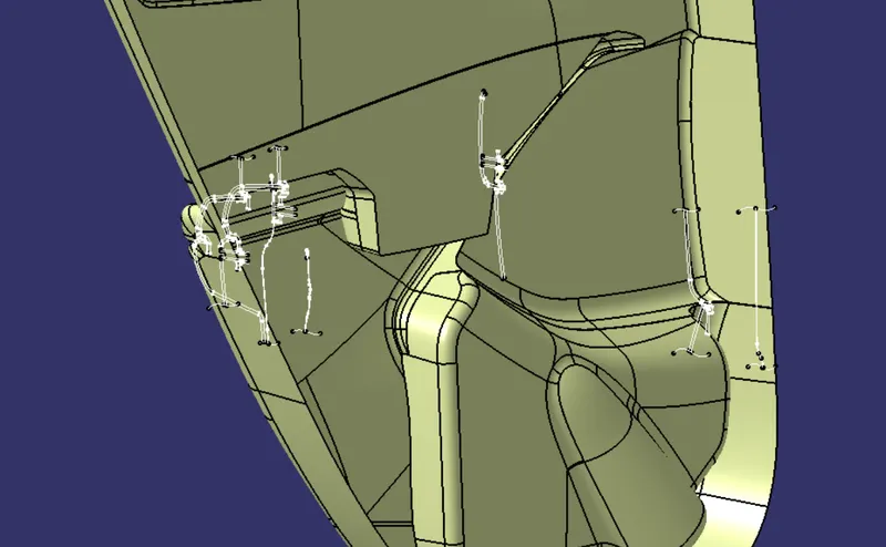
- Class A surface with reference sketches.
Procedure:
- Split the class A surfaces and add geometrical set with proper name in it and check with the reference sketches.
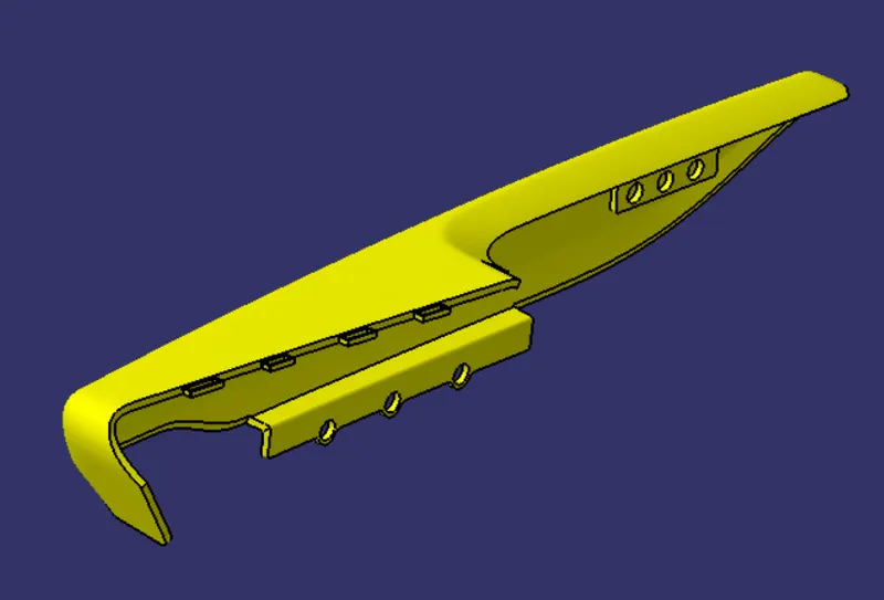
1) Upper arm rest:
- Create a Class B and C surface with Class A surface and convert the surfaces into solid.
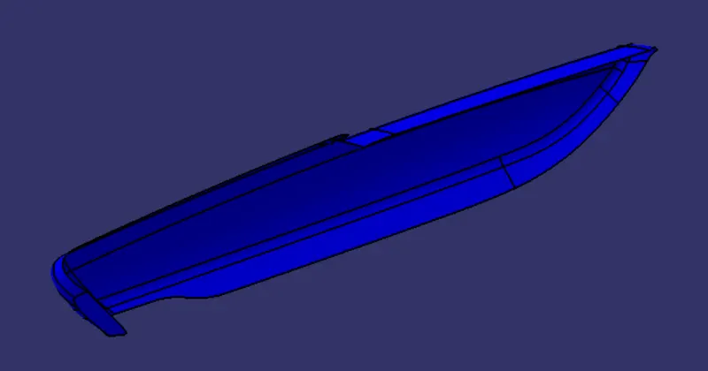
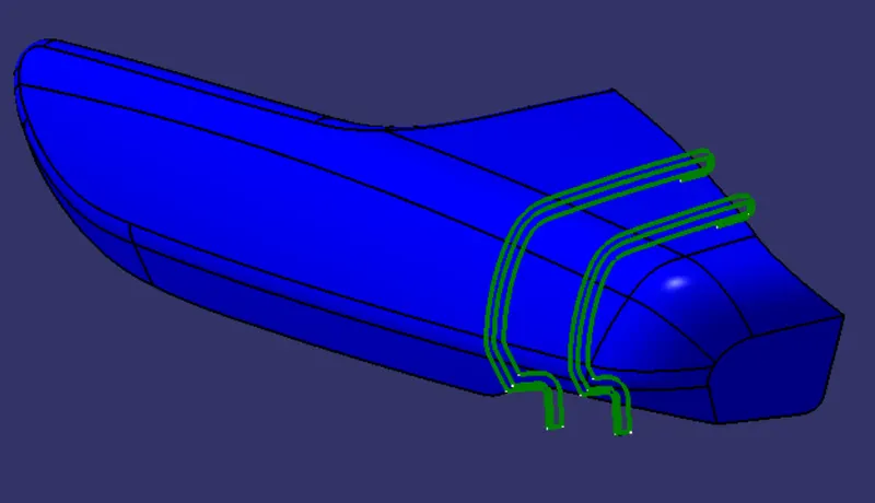
- Class B surface offset from the class A surface of 2.5mm and added flanges to it.
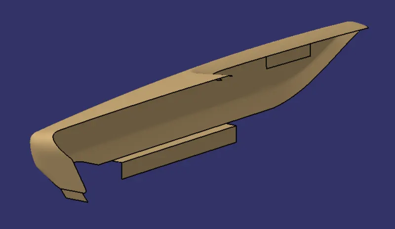
- Class C surface adding the Class A and B surfaces together by class C surface.
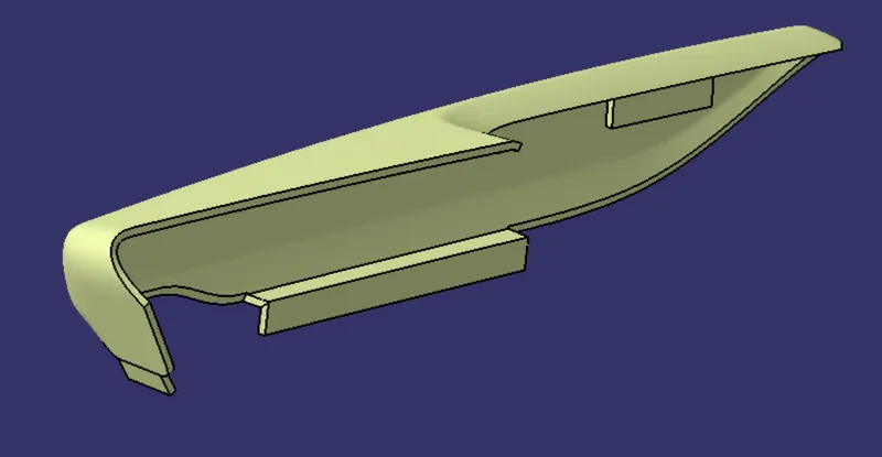
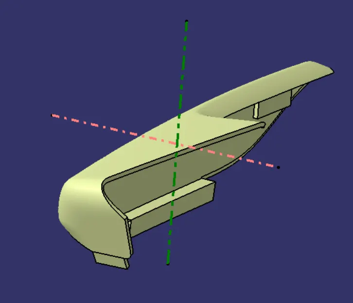
- Tooling Axis created for the part.
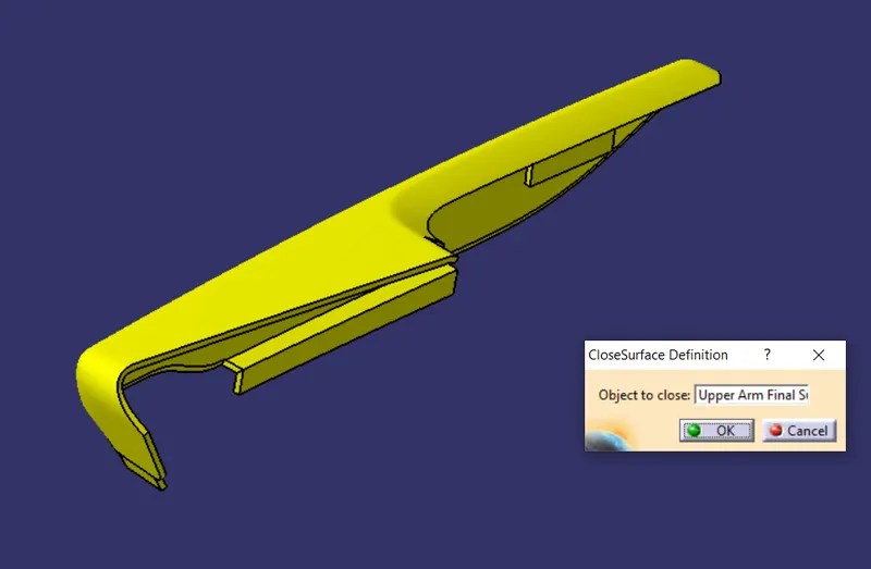
- Close the surfaces and convert it into body by close surface.
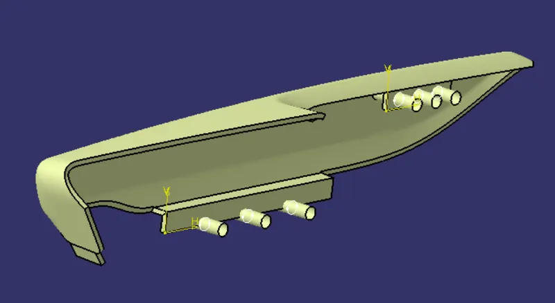
- Create a Holes for heat stakes and locators and the sketches are Iso-constrained
- Create a flange for snap fits and trim it.
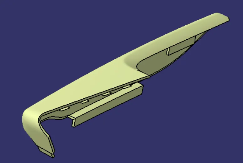
- Split the Extrude for holes and flanges to get holes.
Draft Analysis:
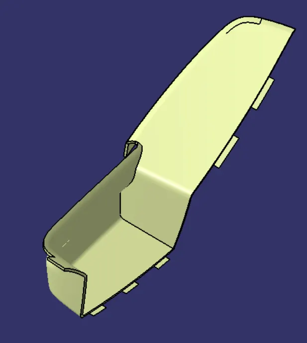
2) Lower Arm rest:
- Class A surface of lower arm rest.
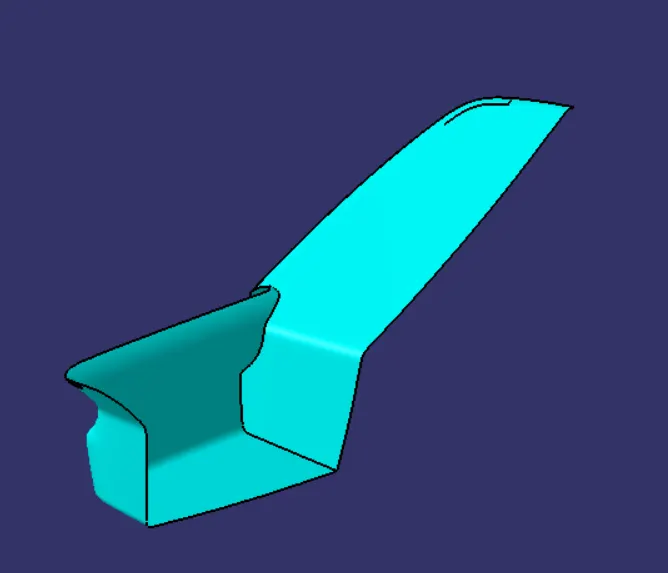
- Create Class B surface by offset class A surface of 2.5mm.
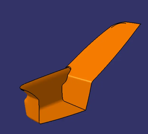
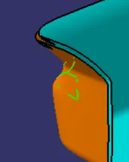
- Create a class C surface by adding the class A and B surfaces and trim the excess surfaces.
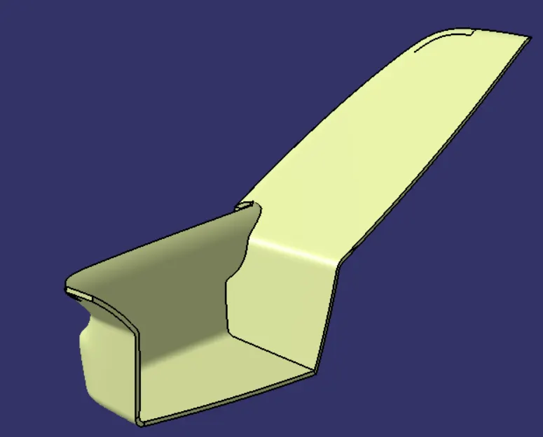
- Close the surface and convert the surface into body.
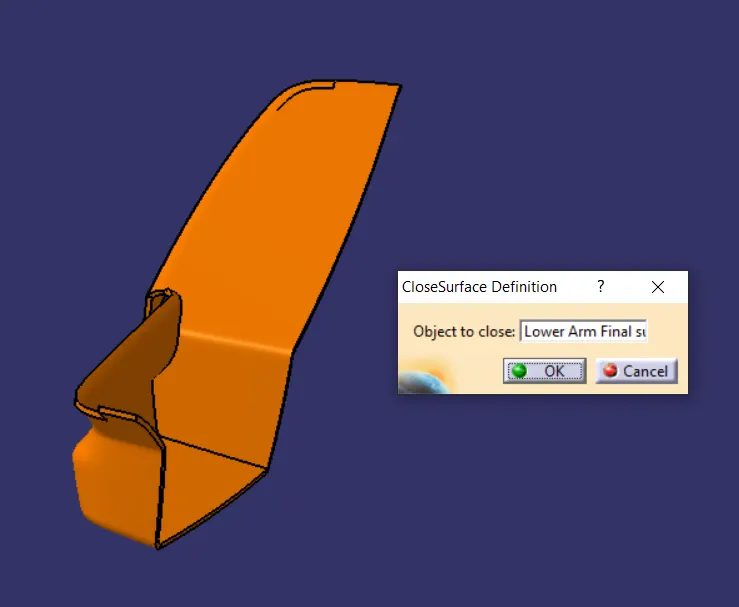
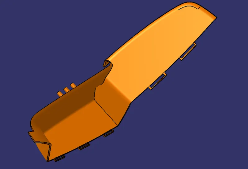
- Create a flanges on the surfaces and extrude it.
- Create a sketch for heat stakes and extrude it to certain values.
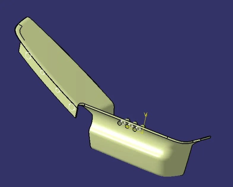
- Create a hole on the flanges and Give draft to the heat stakes.
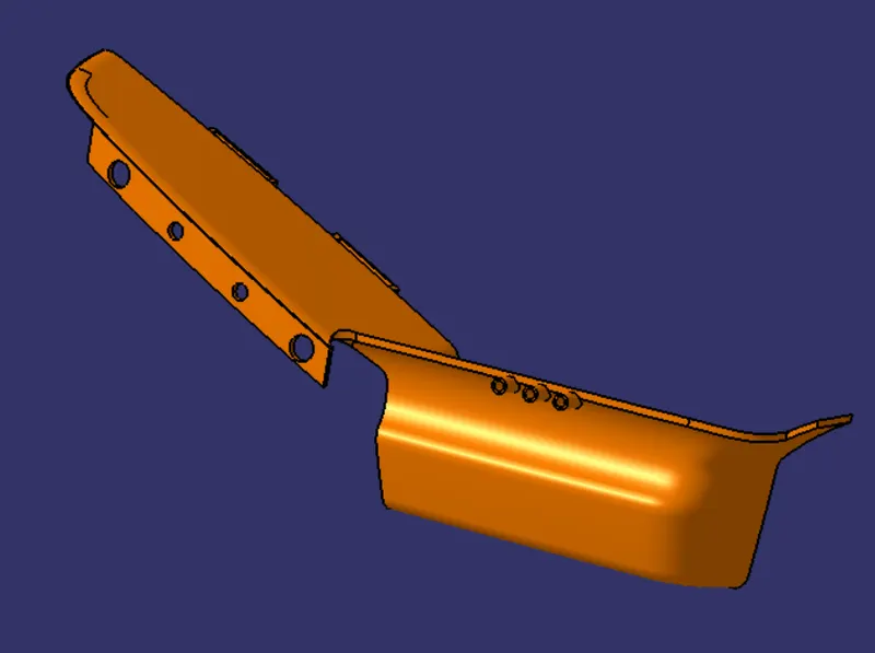
Draft Analysis:
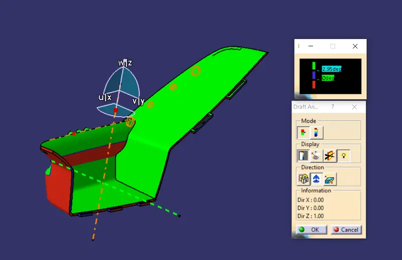
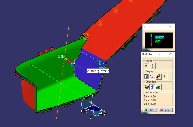
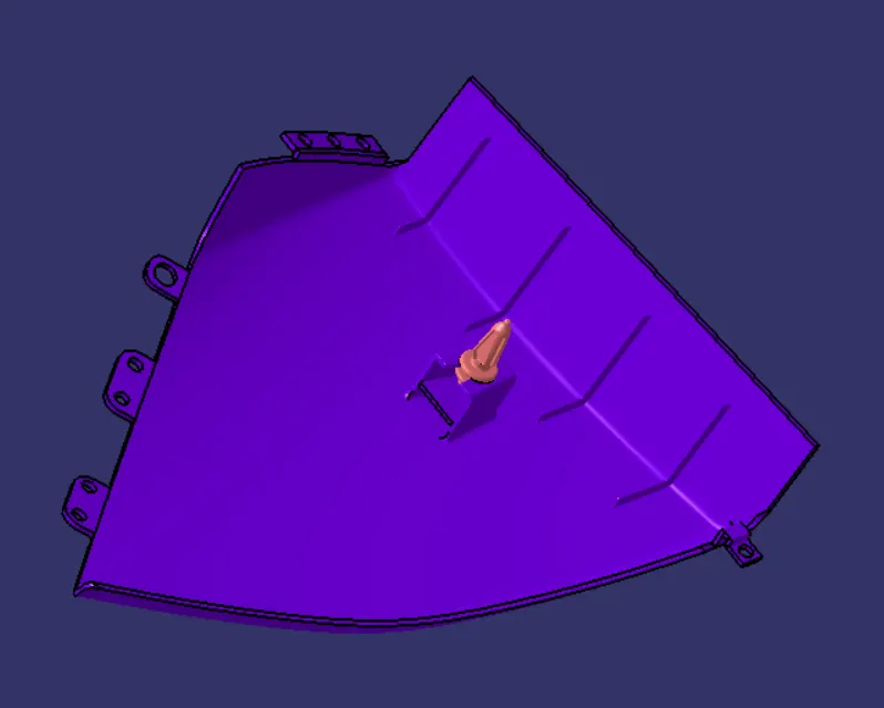
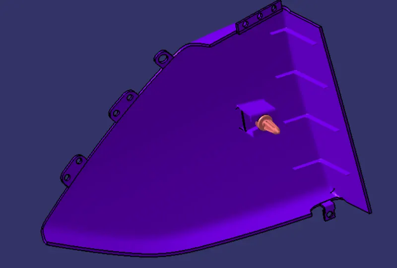
3) Map Pocket:
- Create a class A surface of map pocket.
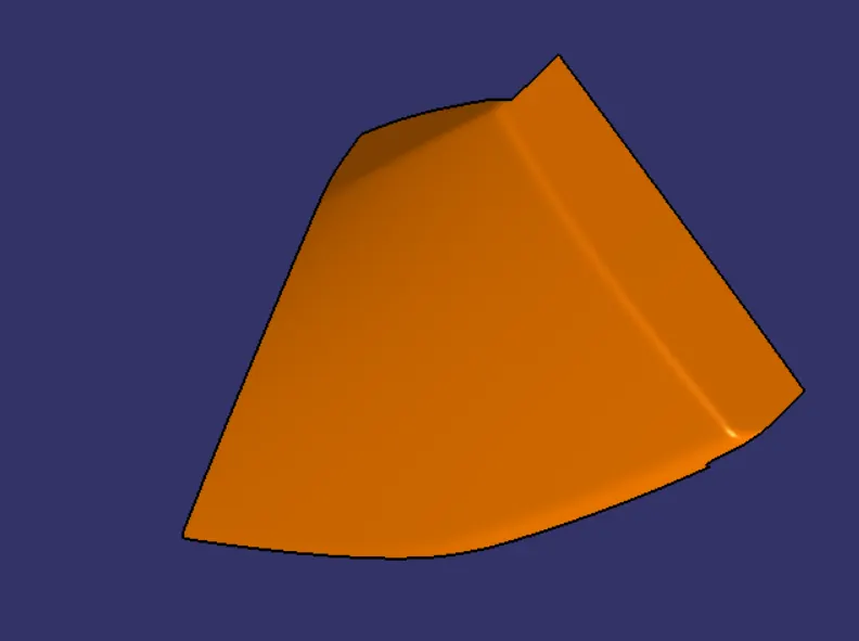
- Create a Class B surface, offset it to 2.5mm and create flanges to the edges as per the ref sketch.
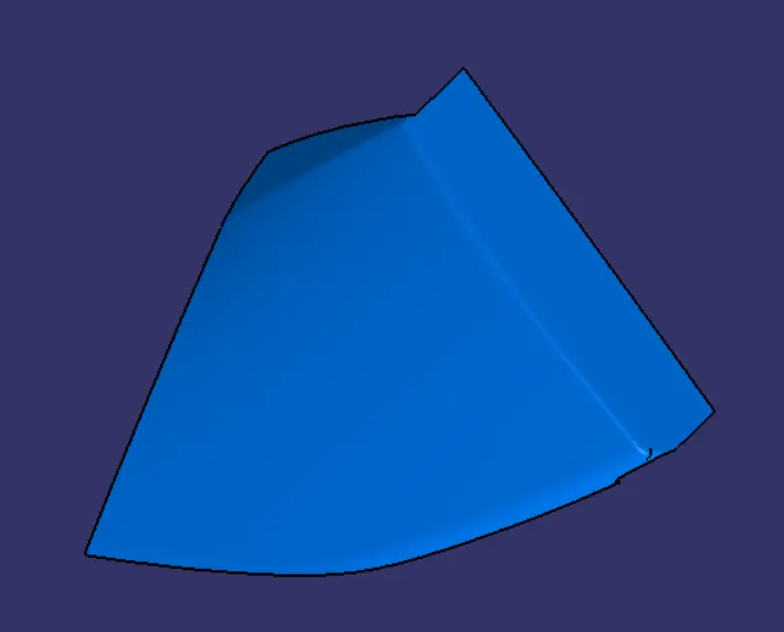
- Create a class C surface by joining the class A,B surfaces and trim the excess surfaces.
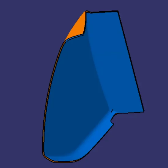
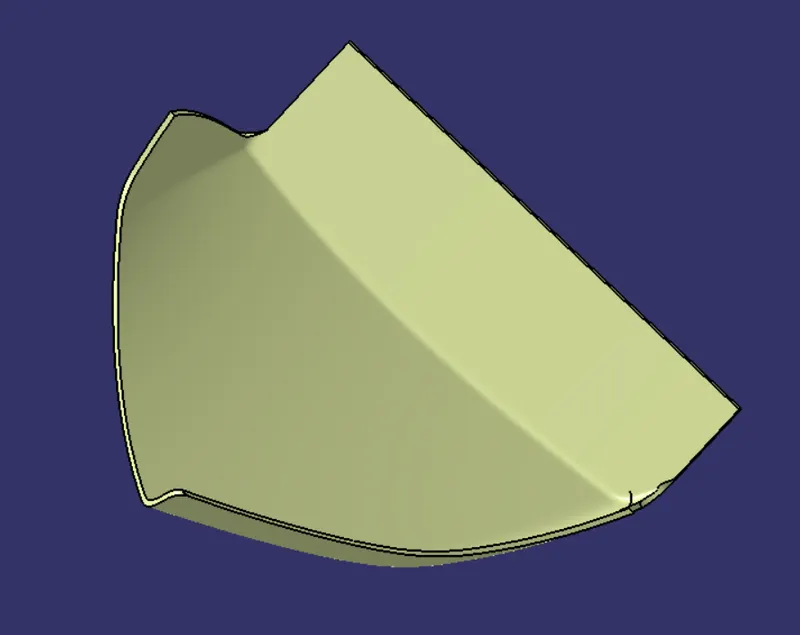
- Close the surface by converting the surface into solid by close surface.
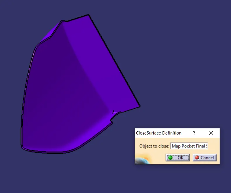
- Create a tooling axis of the map pocket.
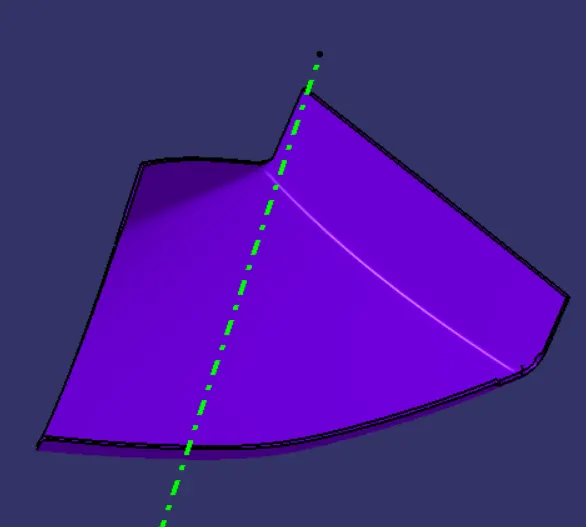
- Create flanges,Holes,Heat stakes,Ribs,Dog house and push clips.
Draft Analysis:
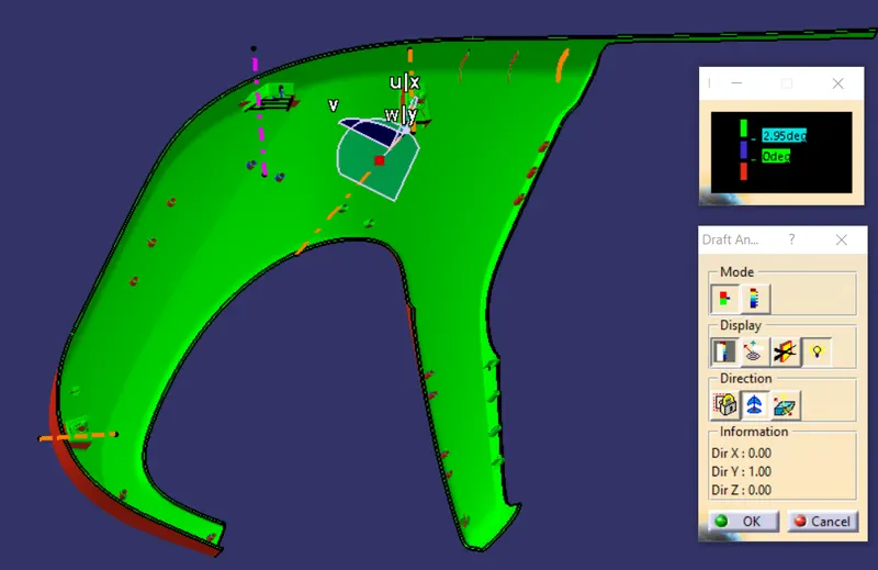
4) Lower Substrate:
- Create a class A surface of lower substrate.
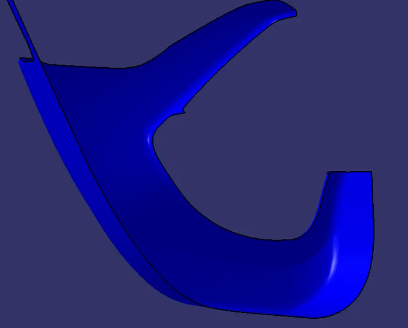
- Create a Class B surface by offset the class A surface to 2.5mm.
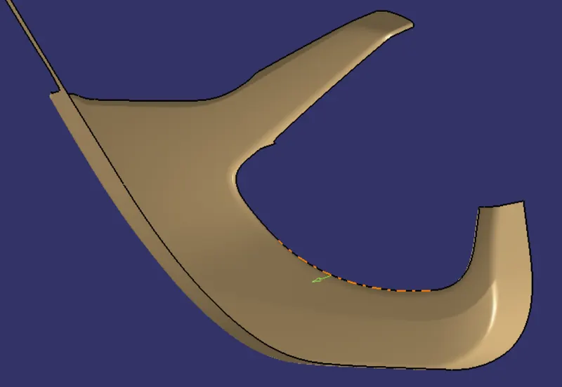
- Create Class C surface by joining the class A and B surfaces together and trim the excess surfaces.
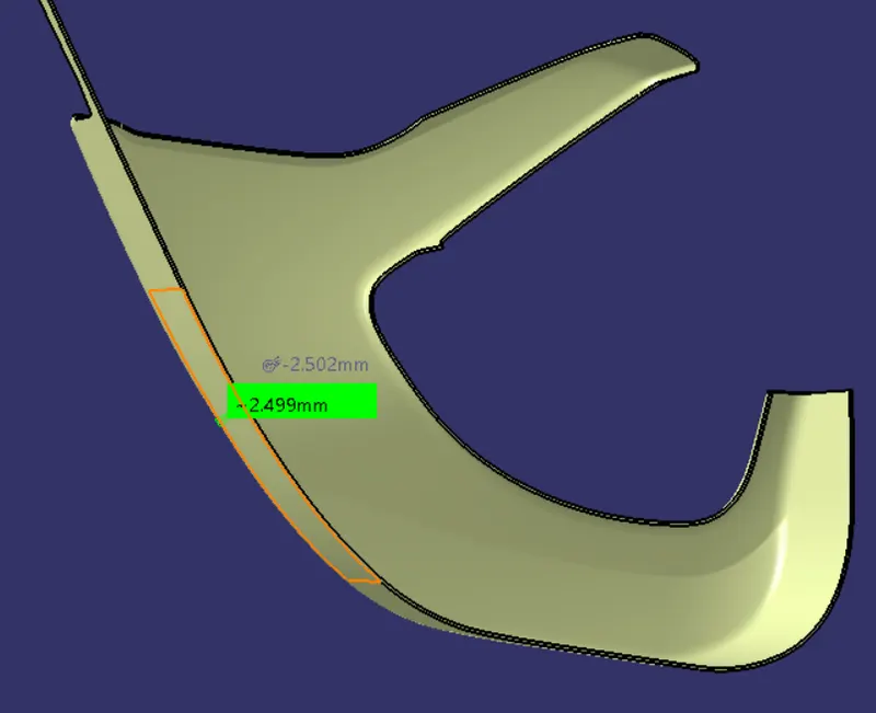
- Close the surfaces and convert the surface into solid body by close surface option.
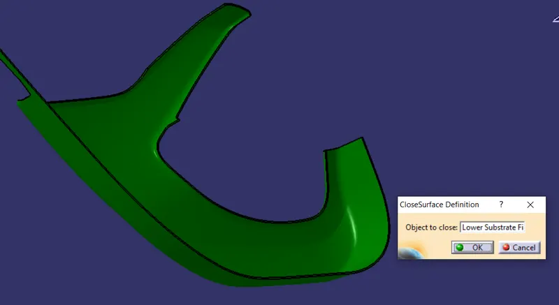
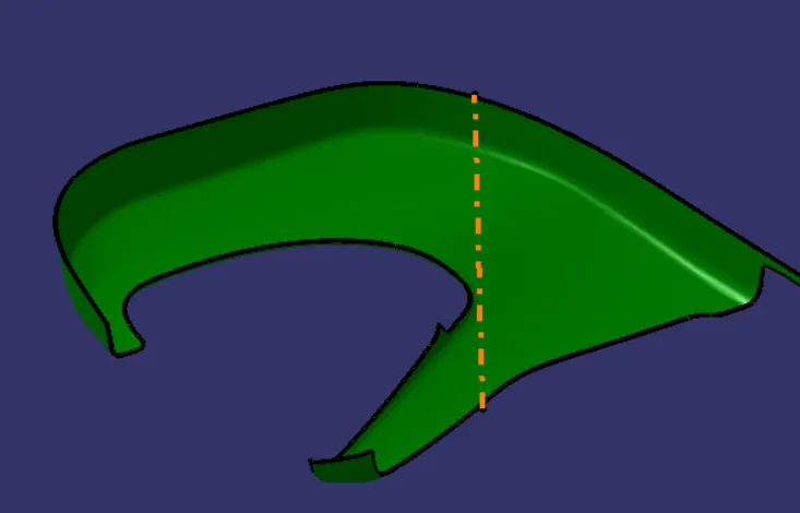
- Create a tooling axis of the part.
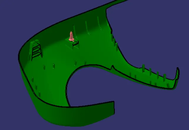
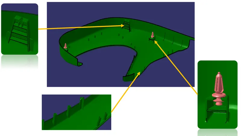
- Create a flanges,dog house,ribs,screw boss heat stakes and locators.
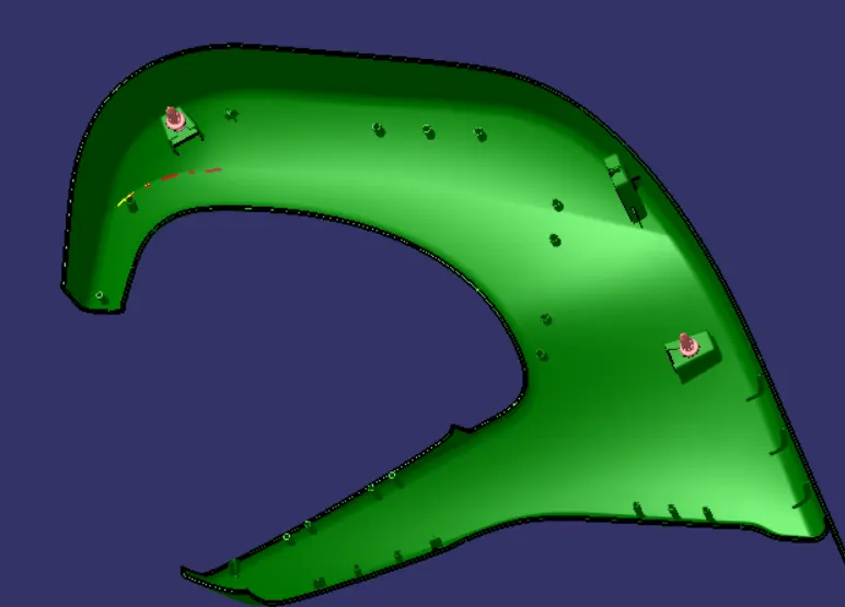
Draft Analysis:
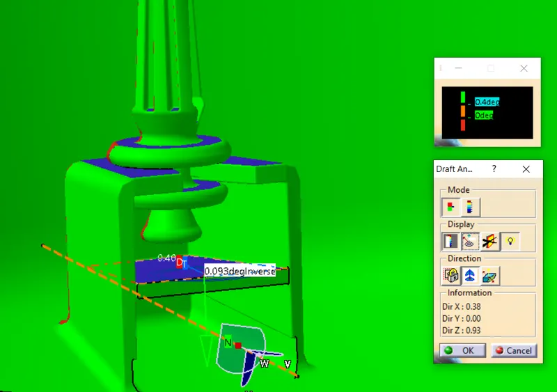
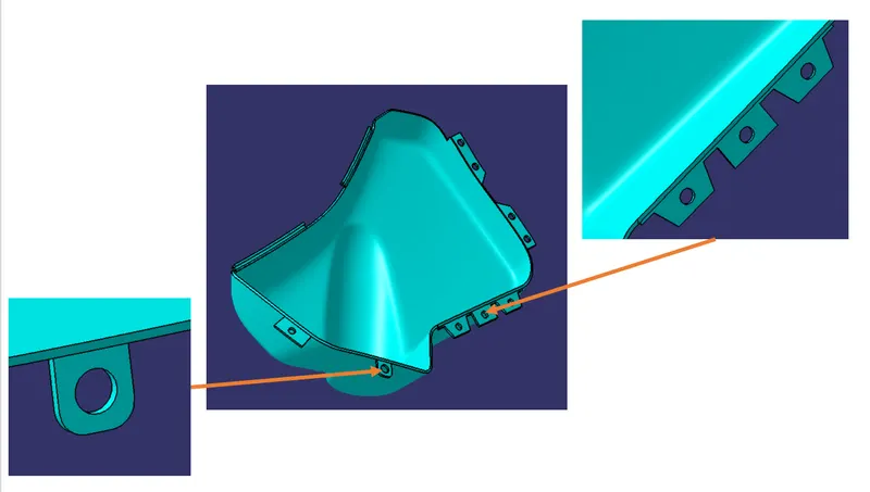
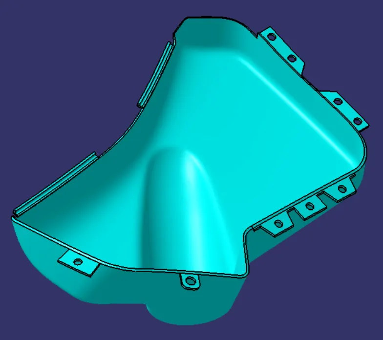
5) Bottle Holder Map pocket:
- Create a class A surface of Bottle holder.
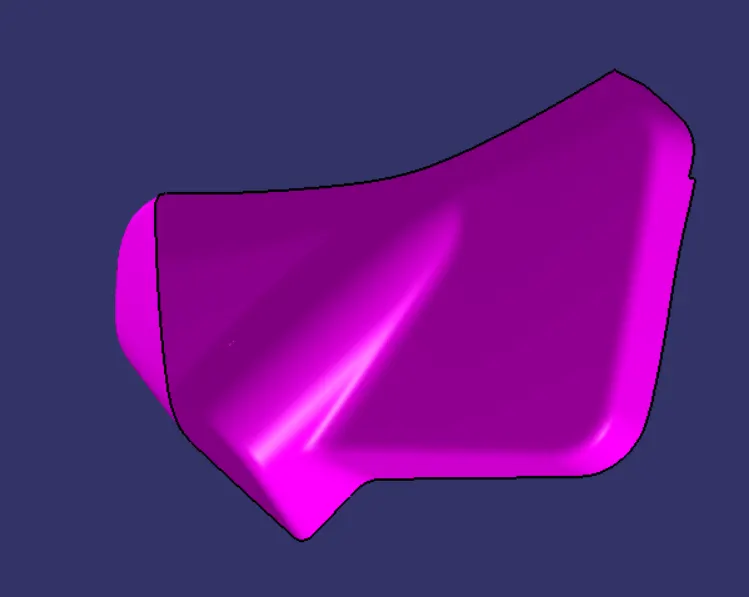
- Create a Class B surface by offset to value of 2.5mm from class A surface.
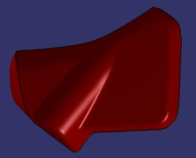
- Create a Class C surface by adding the class A and B surfaces and trim the excess surfaces.
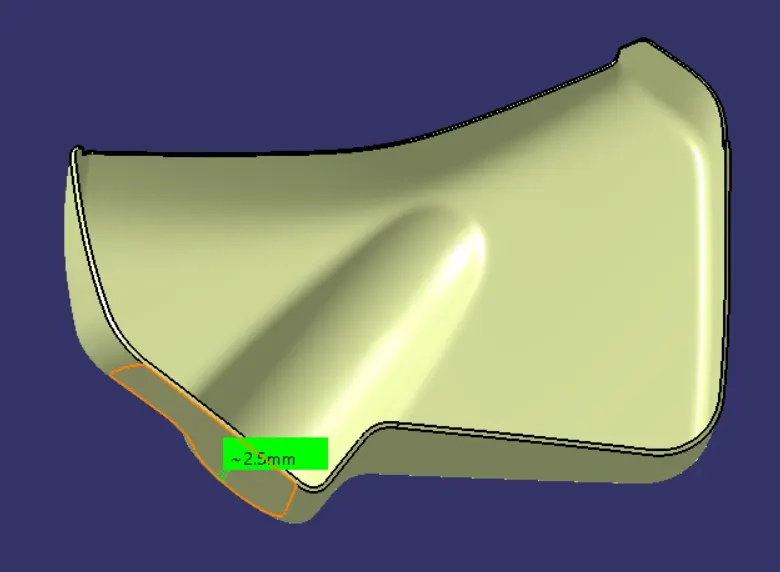
- Close the surface by converting the surfaces into solid by close surface option.
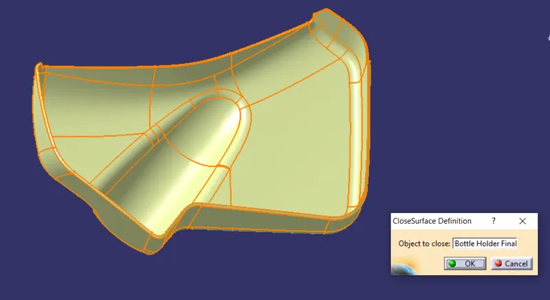
- Create a tooling axis and flanges,heat stakes holes,etc.
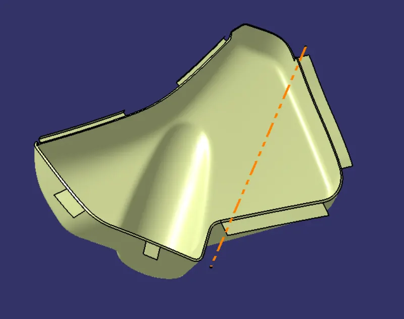
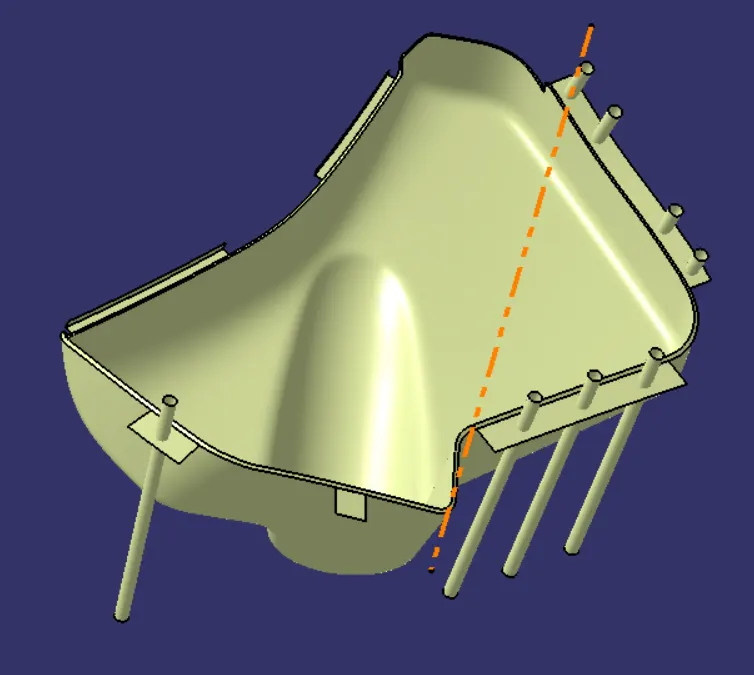
Draft Analysis:
6) Upper Door Panel:
- Create a Class A surface of upper door panel.
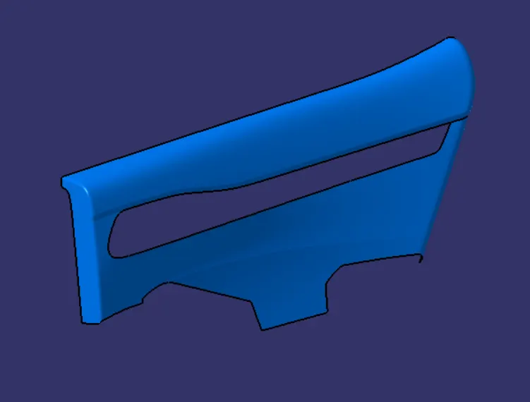
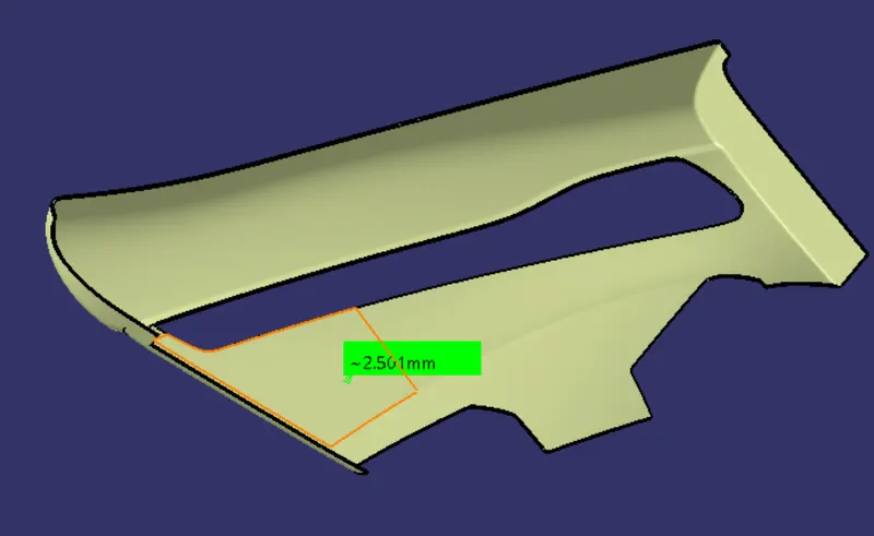
- Create a Class B surface by offset the value to 2.5mm from the class A surface.
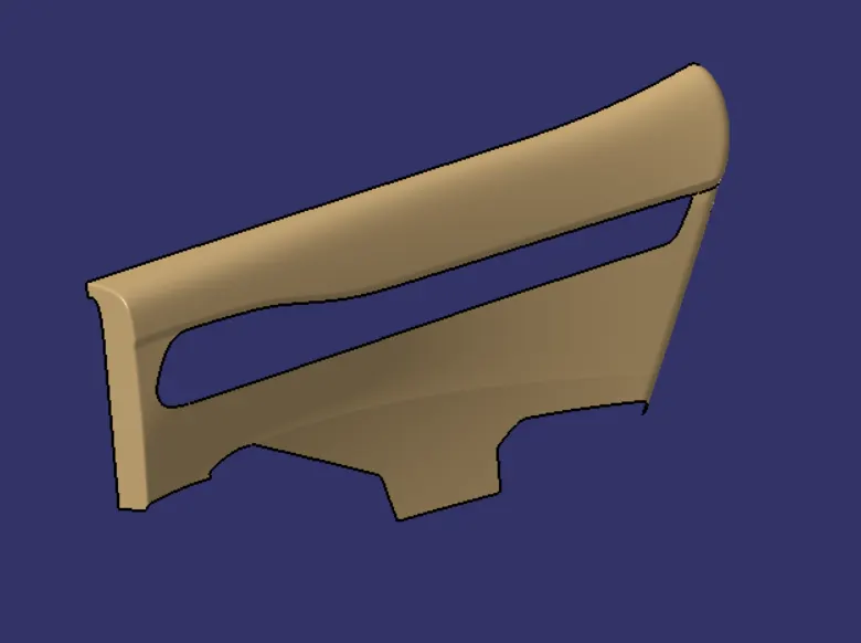
- Create a Class C surface by joining the class A surface and class B surface and trim the excess surfaces.
- Close the surface by making the surface into solid by close surface option.
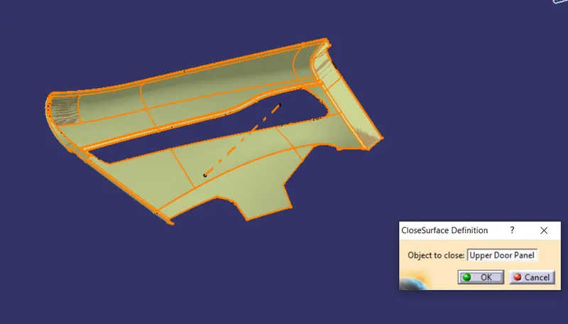
- Create Tooling axis and create the flanges,holes ,ribs,Heat stakes,dog House and screw bosses.

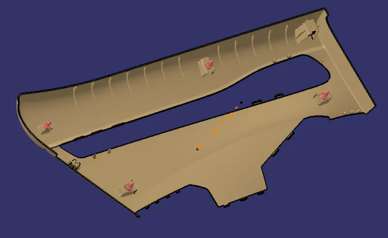
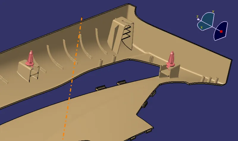
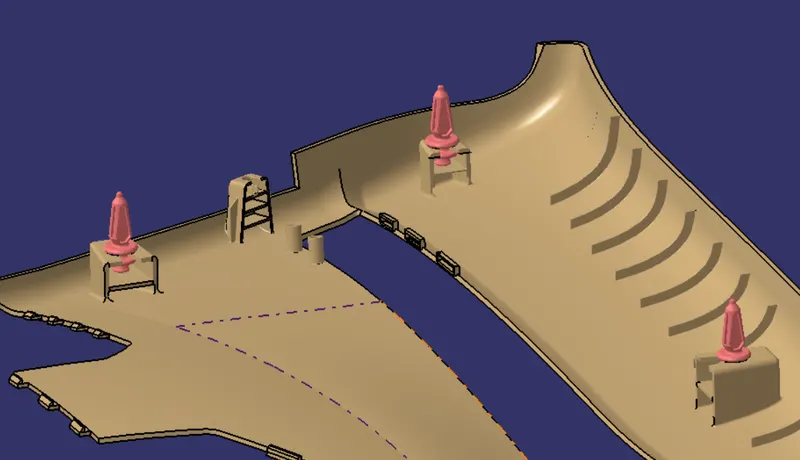
Draft Analysis:
7) Door Handle Panel:
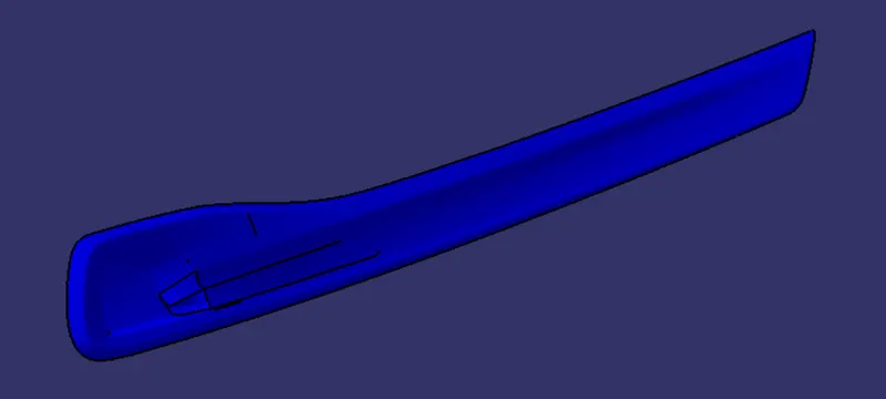
- Create a CLass A surface of Door Handle panel.
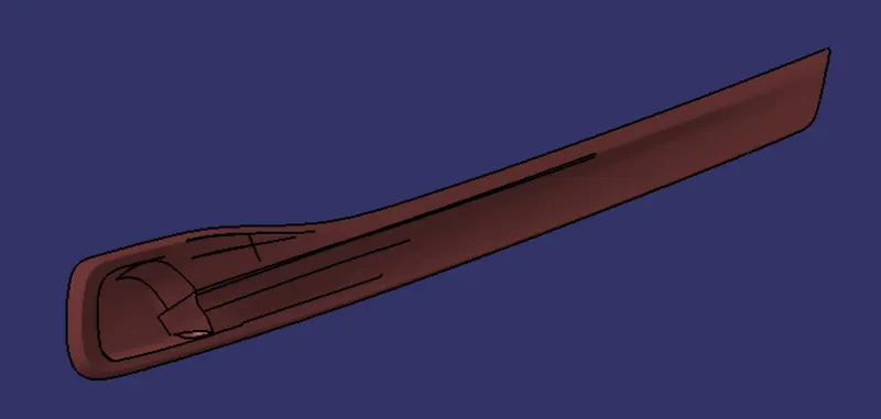
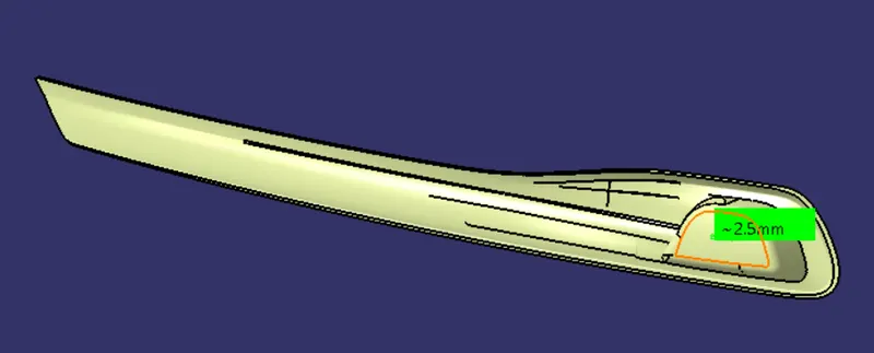
- Create a class B surface by offset into 2.5mm by class A surface.
- Create Class C surface by joining the class A and B surface and trim the excess surfaces.
- Close the surface by making the surfaces into solid by close surface option.
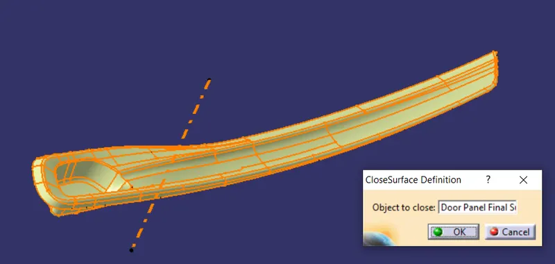
- Create a tooling axis and flanges,holes,Snap fit locators.
Draft Analysis:
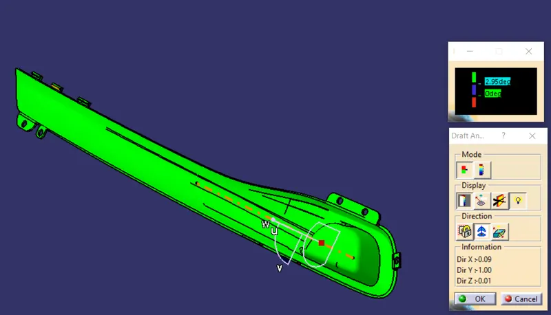
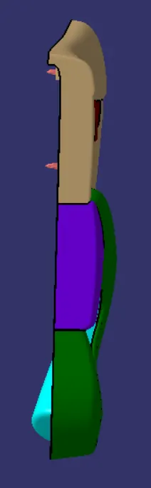
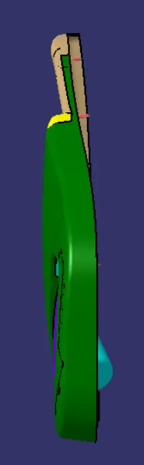
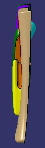
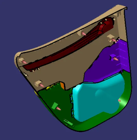
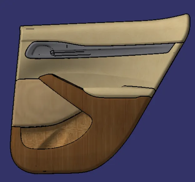
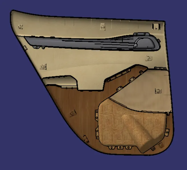
Final Door Trim Panel:
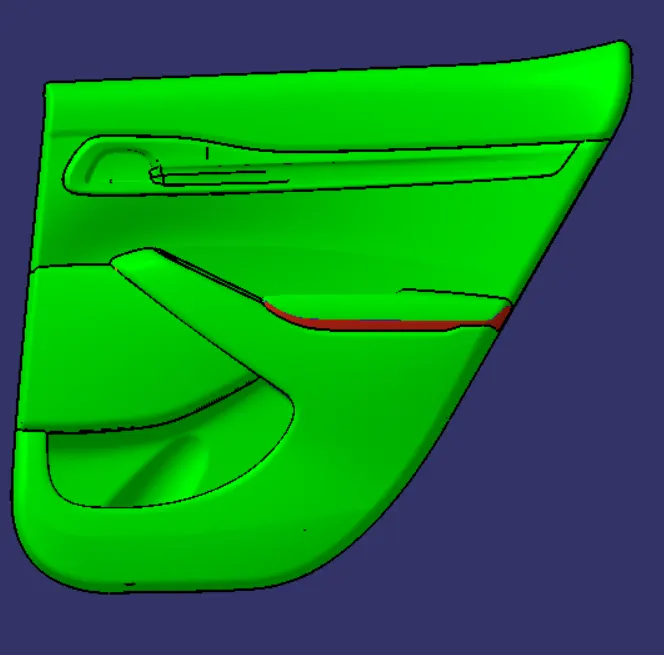
Views :
Front View:
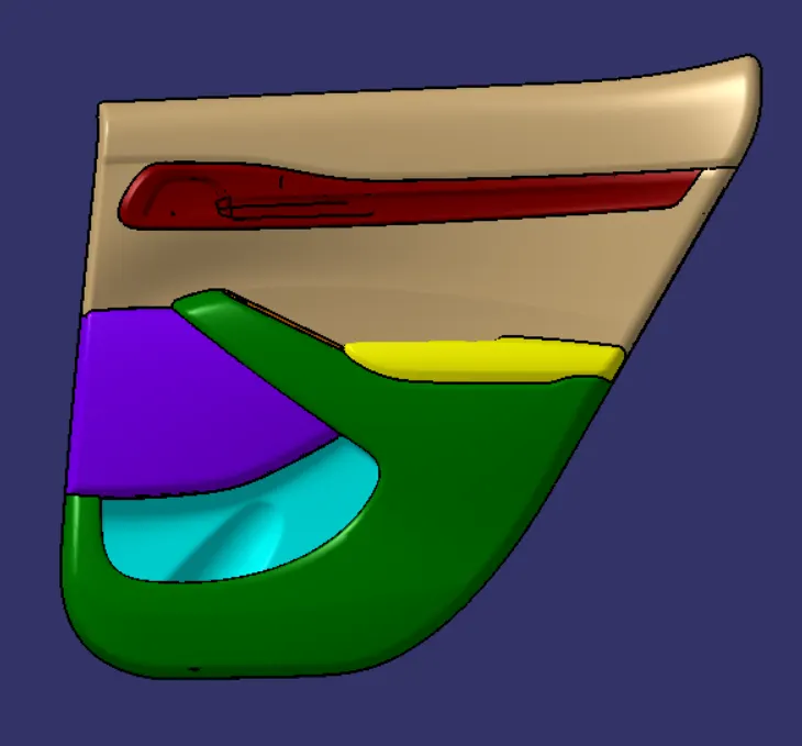
Back View:
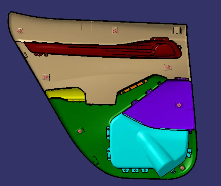
Side View:
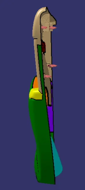
Top View:
Isometric View:
Material added:
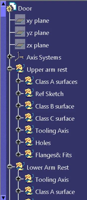
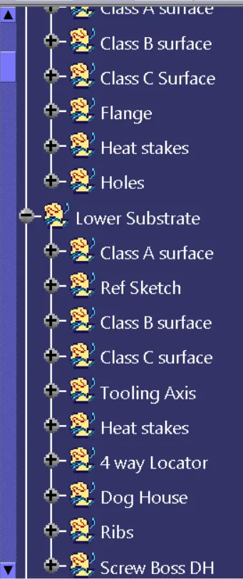
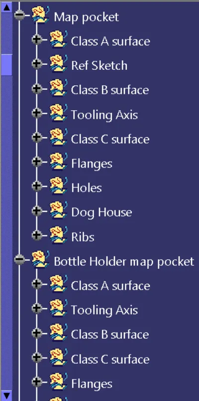
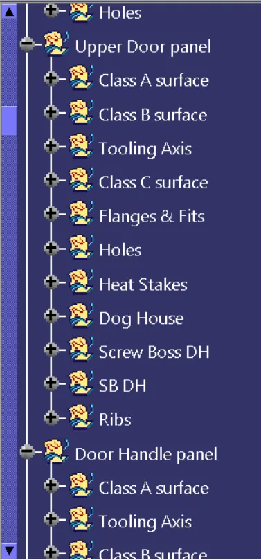
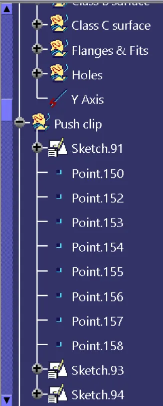
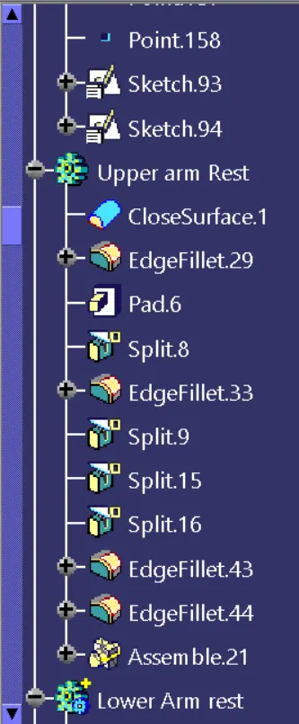
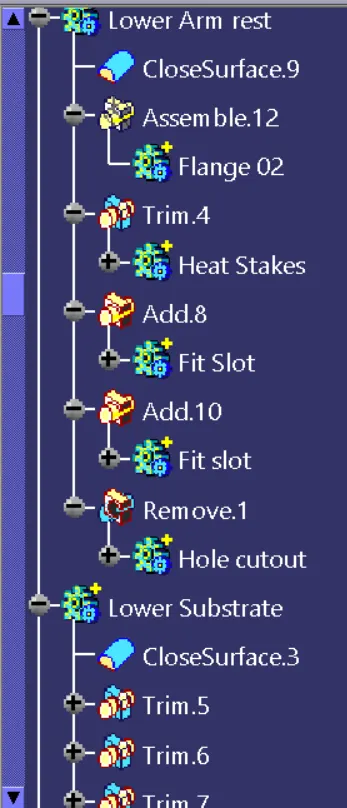
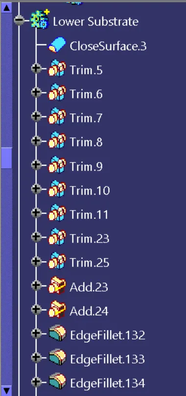
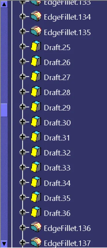
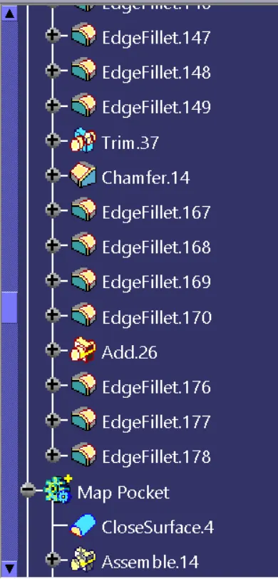
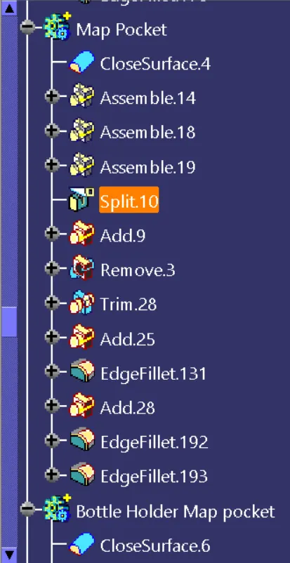
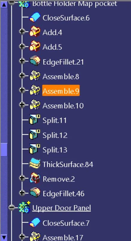
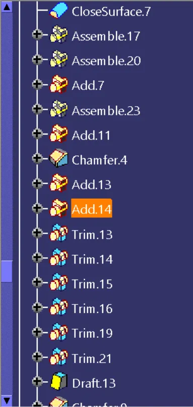
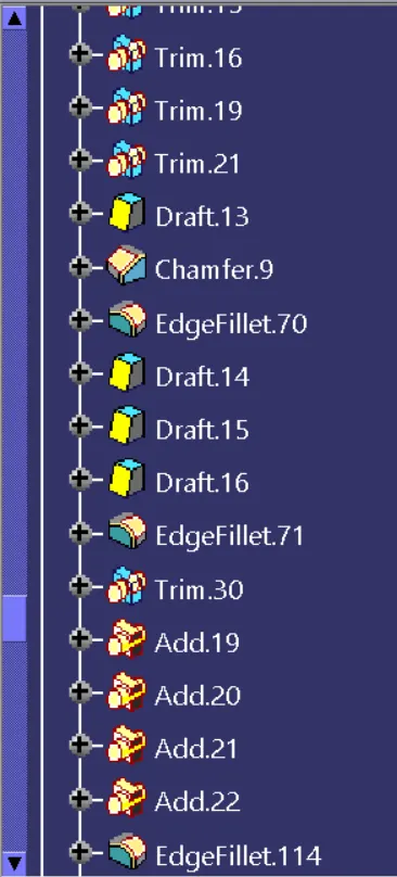
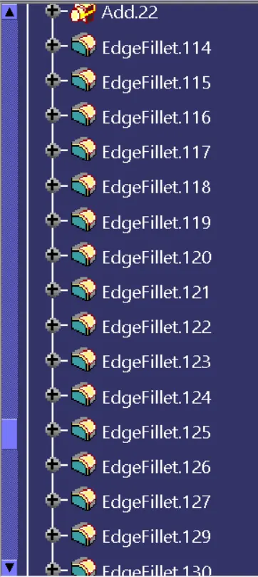
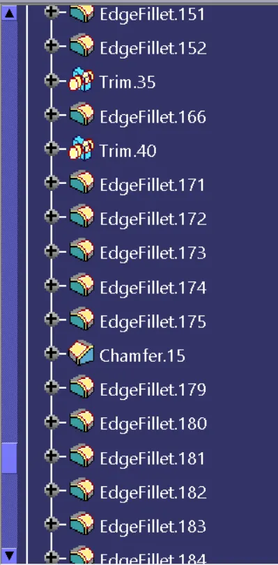
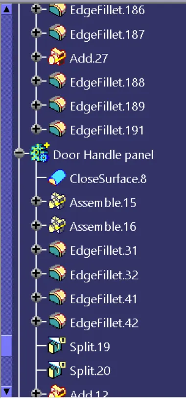
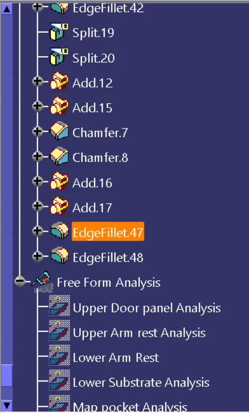
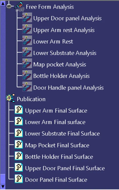
Feature Tree Manager:
Conclusion:
- Finally the Door trim panel is made with Class A,B and C surfaces along with the Heat stakes,Dog houses,Ribs,Locators and Snap fits.
- Learned about the Injection molding process and the draft analysis done on the model.
- Finally applying material to the door gives realistic look.