Week 11 - Final project
DOOR TRIM PANEL
In this project we are designing interior trim of the car i.e., door trim panel consider mostly as asthetic parts of the automotive.
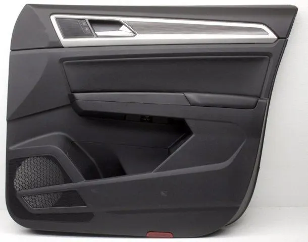
Fig: Door trim panel
We have been provided with a Class A surface and Master section of the door trim panel by using which we are designing a closed component and providing a B side features as per requirement.
The input class A surface provided is:
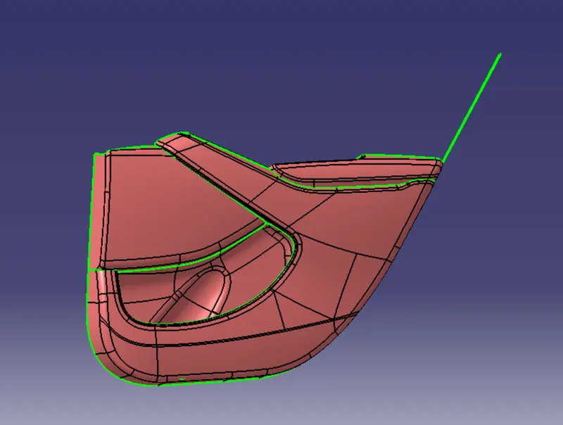
Fig: Class A Suface
UPPER MAP POCKET
Extracting the surface from class A.
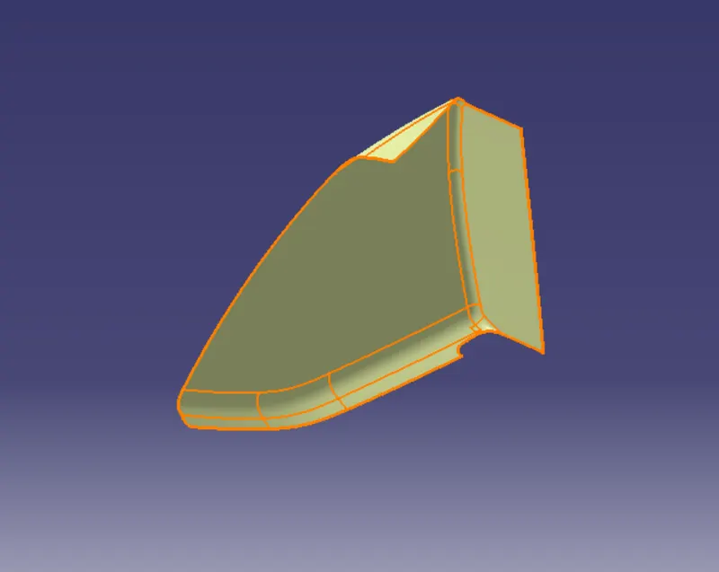
Fig: Extracted Surface
Creating Tooling axis
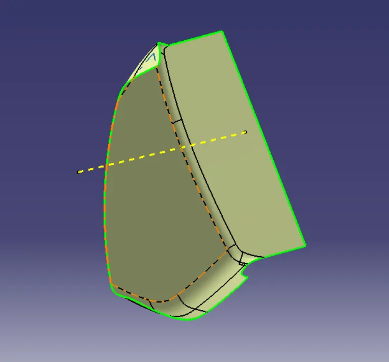
Fig: Tooling Axis
Designing of Class B Surface from the extracted surface.
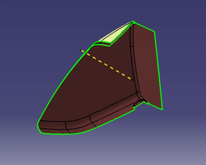
Fig: Class B Surface
Designing a class C surface to join both class A and Class B
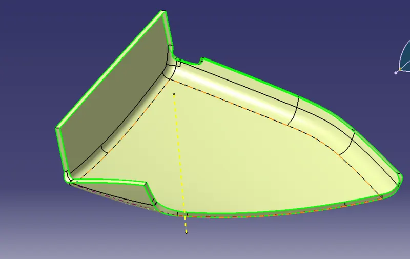
Fig: Class C Surface
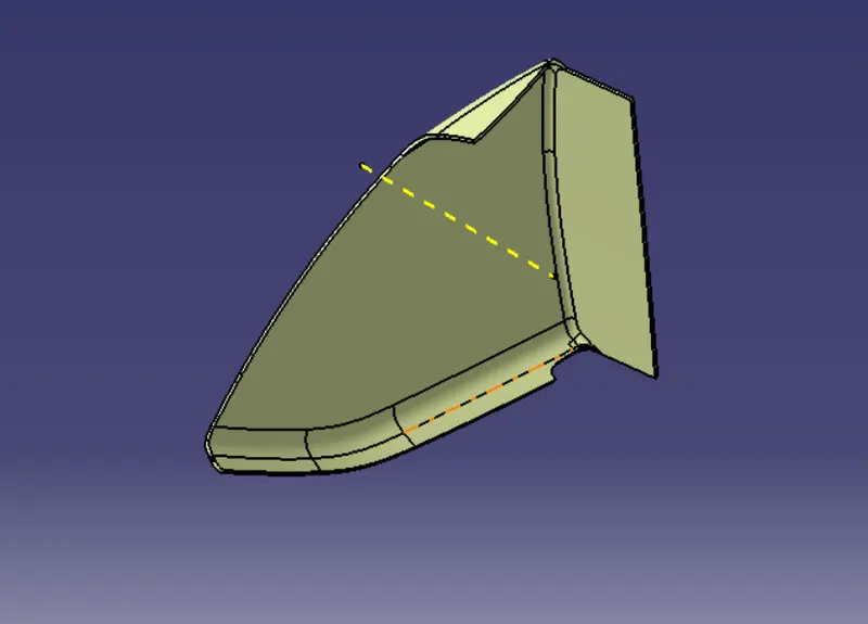
Fig: Closed Surface
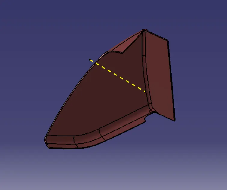
Fig: Closed part body
DRAFT ANALYSIS
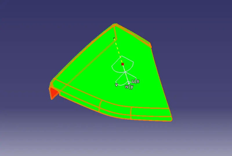
Fig: Draft Analysis
MAP POCKET
Extracting surface and checking for discontinuity.
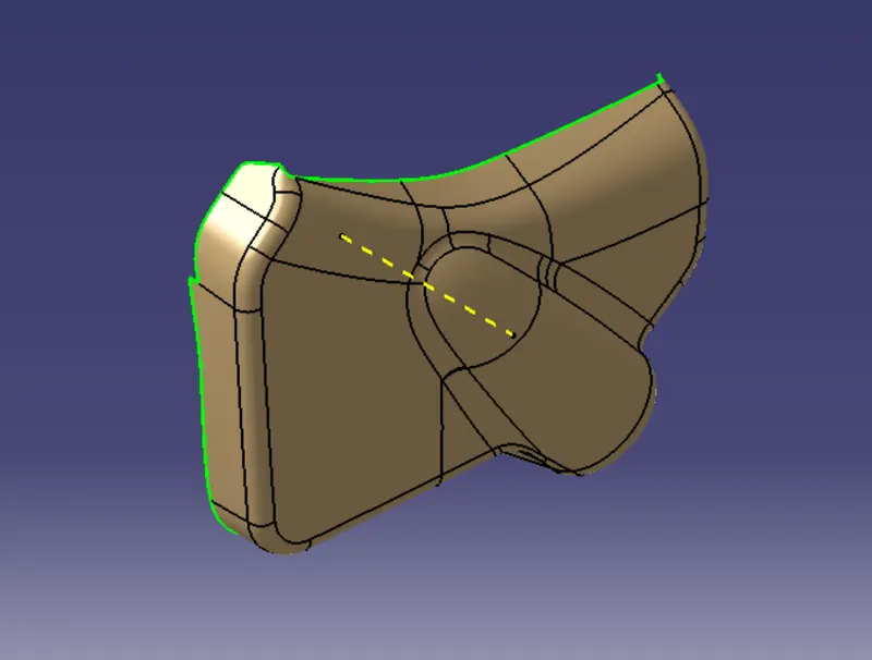
Fig: Extracted Surface
Creating tooling axis.
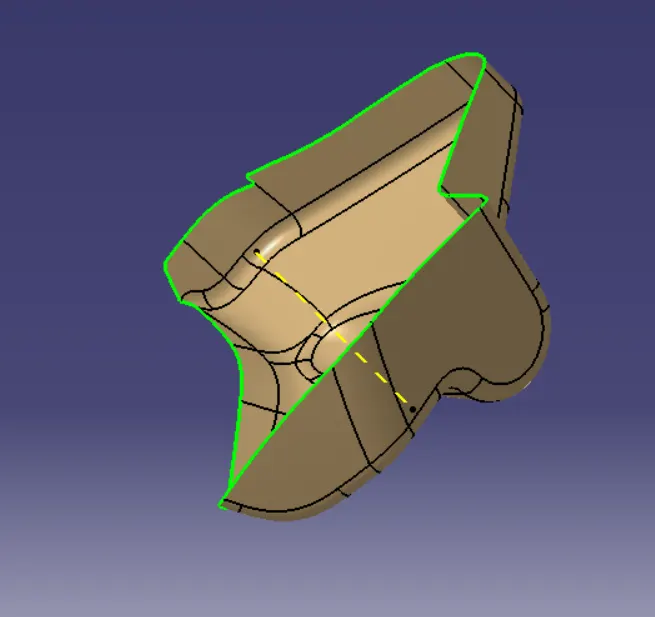
Fig: Tooling Axis
Offsetting Class A surface to aquire Class B surface.
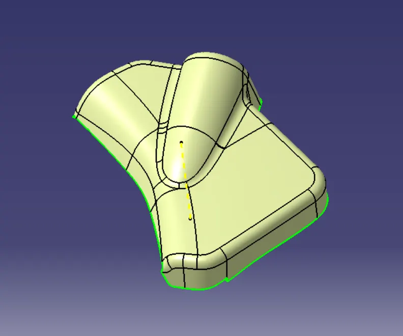
Fig: Class B Surface
Sweep the class c surface having draft of 3 degree.
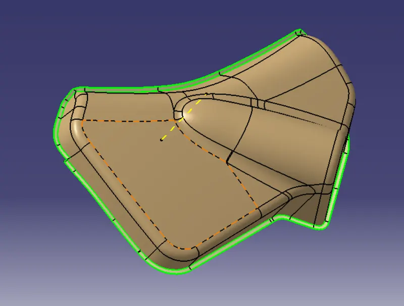
Fig: Class C surface
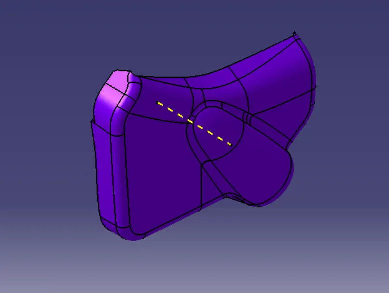
Fig: Solid Component
Draft Analysis
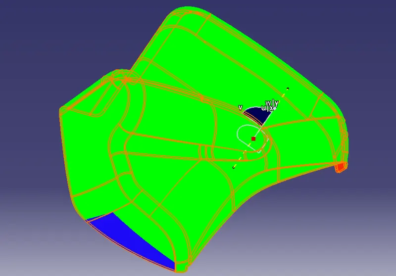
Fig: Draft Analysis
ARM REST
Extracting surface from the given clas A surface and checking for the discontinuity.
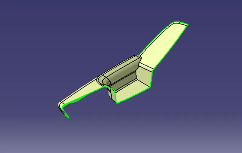
Fig:Extracted Surface
Creating tooling axis for the component
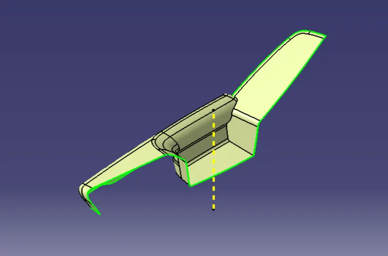
Fig: Tooling Axis
For creation of Class B surface we offsetting class A surface at 2.5 mm and checked the discontinuity and rectified the error.
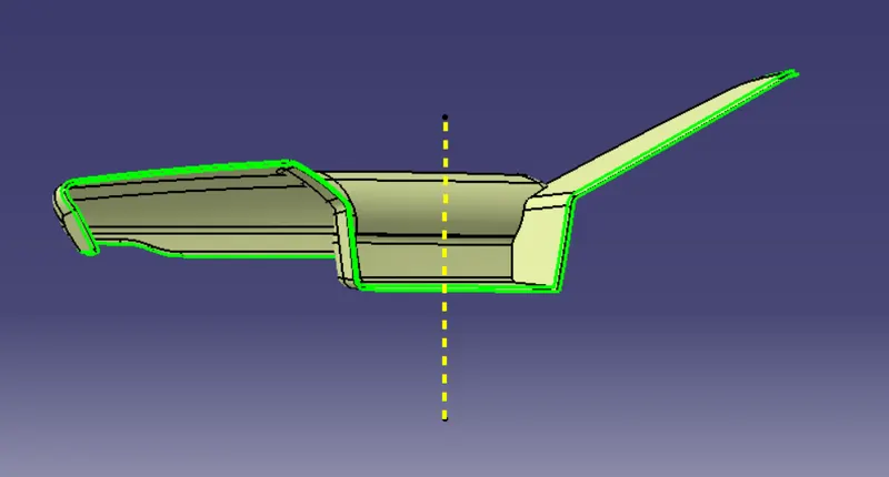
Fig: Class B Surface
Creating a Class C surface with a draft of 3mm to join class A and class B.
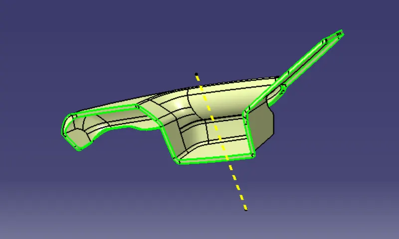
Fig: Class C Surface
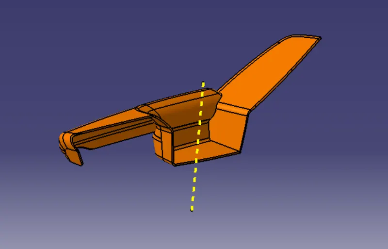
Fig: Solid Component
DRAFT ANALYSIS
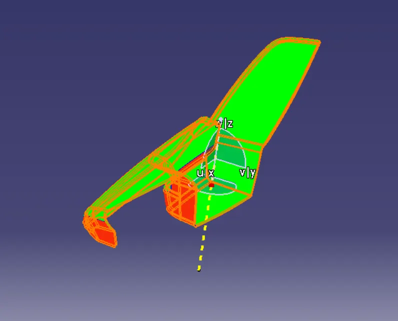
Fig: Draft Analysis
LOWER SUBSTRATE
Extracting the class A surface and checking for the discontinuity.
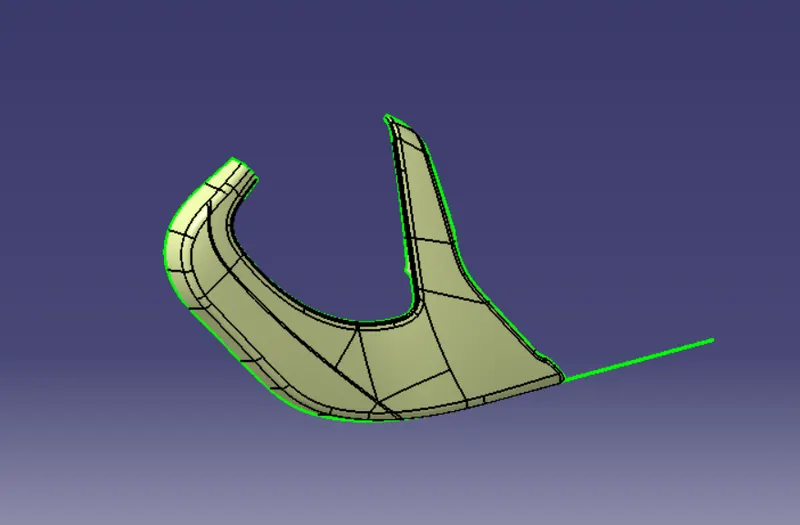
Fig: Extracted Surface
Creating a tooling axis
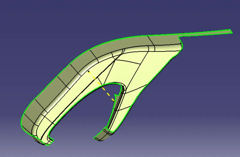
Fig: Tooling Axis
Creating a Class B surface by offsetting Class A surface
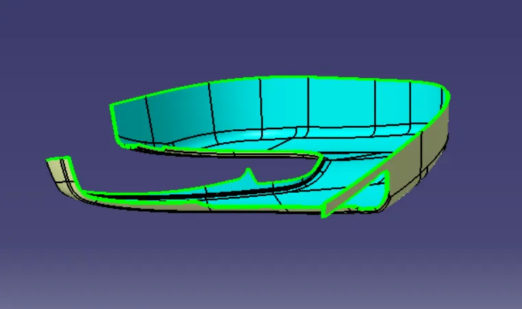
Fig: Class B Surface
Creating a class C surface by using sweep command at 3 degree draft angle.
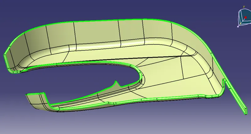
Fig: Class C Surface
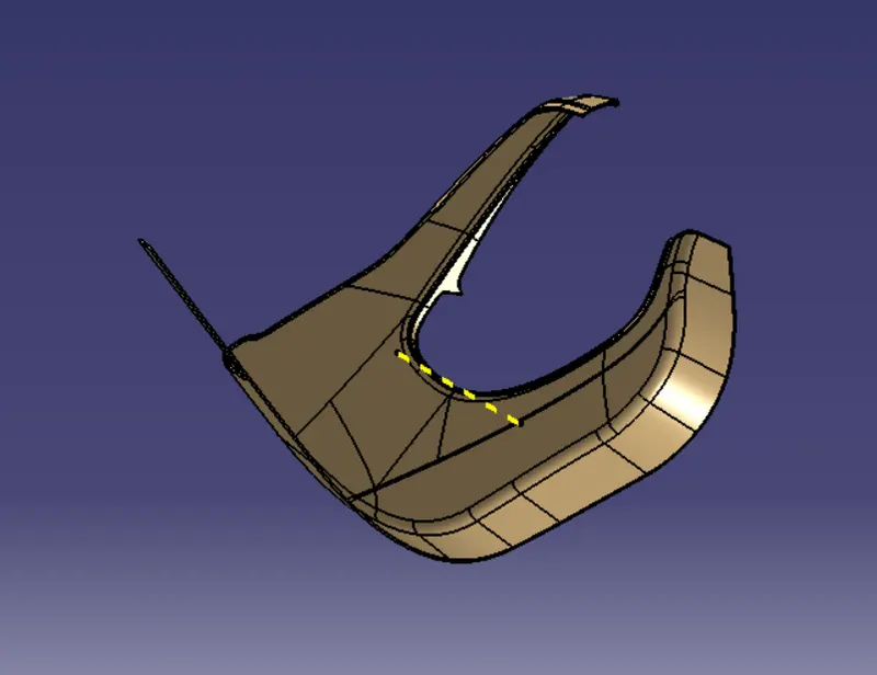
Fig: Solid Component
Draft Analysis
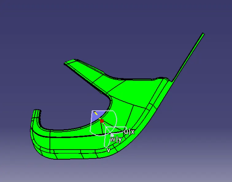
Fig: Draft Analysis
FLANGES AND HEAT STAKES
Flanges and heat stakes are created as per the master section provided.
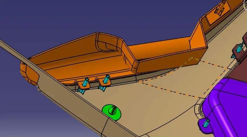
Fig: Flanges and Heat Stakes
ASSEMBLY
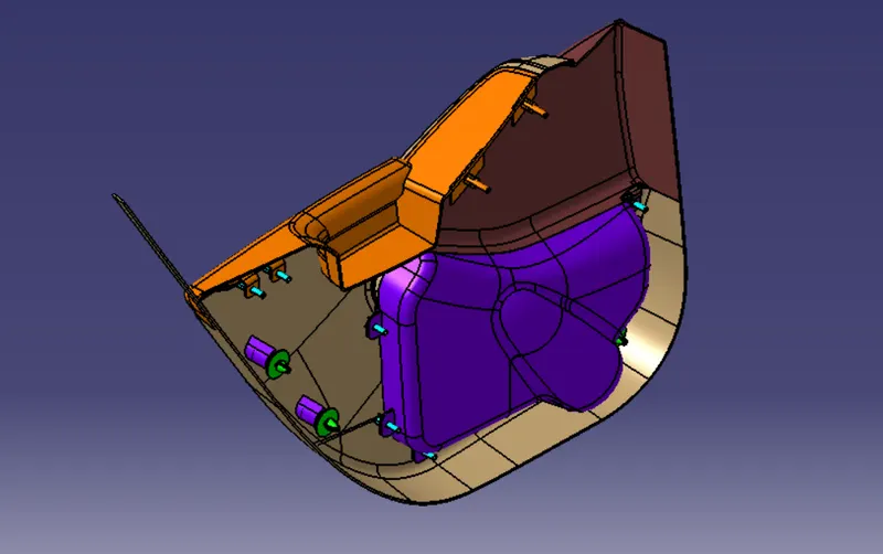
Fig: Isometric View
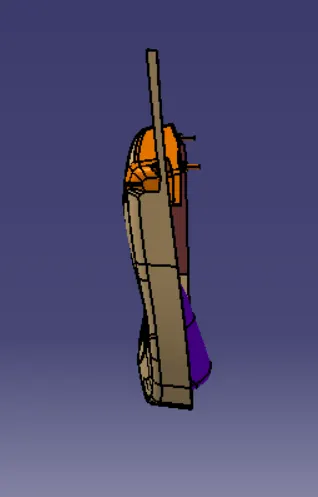
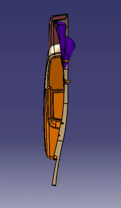
Fig: Front View Fig: Top View
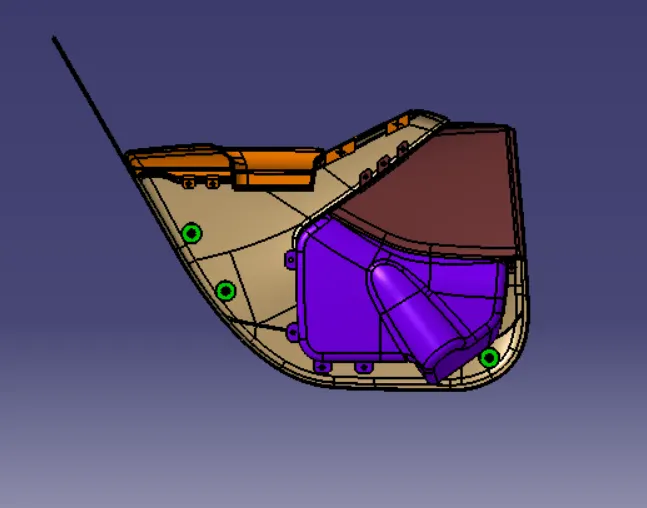
Fig: Side View
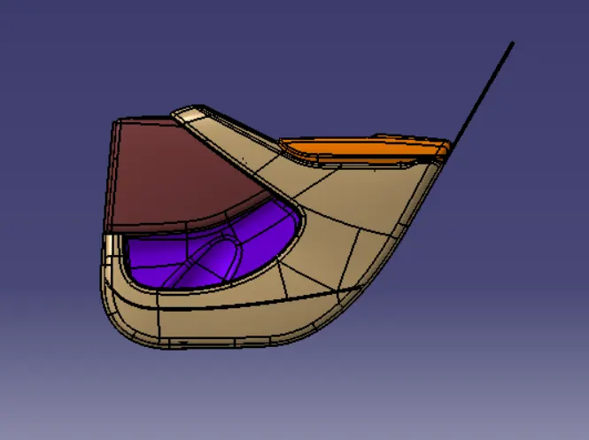
Fig: Back View
Conclusion:
- Understanding the Tools of Catia V5.
- Learning design rules for developing the plastic components.
- Developing the master section and B side features.
- Assembly of components.