Week 11 - Final project
REPORT FOR FINAL PROJECT:
AIM:
To create a door interior part from the inputs of class A surface along with master section by following the design rules followed in tier 1 and OEM industries in Catia v5
SOFTWARE USED:CATIA V5
OBJECTIVES:
- Create a sketch by using Positioned sketch
- All the sketches should be Iso Constrained
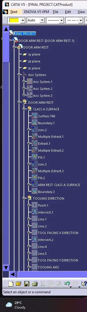
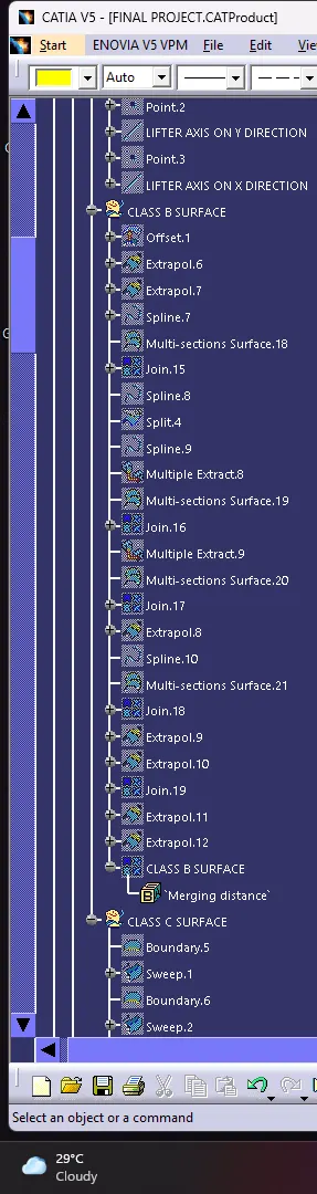
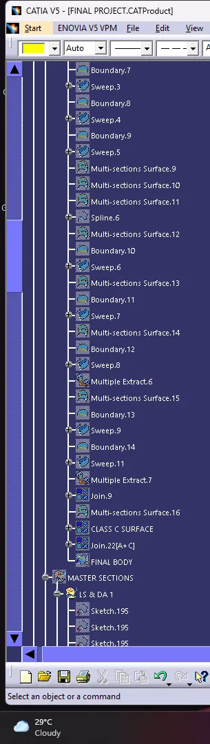
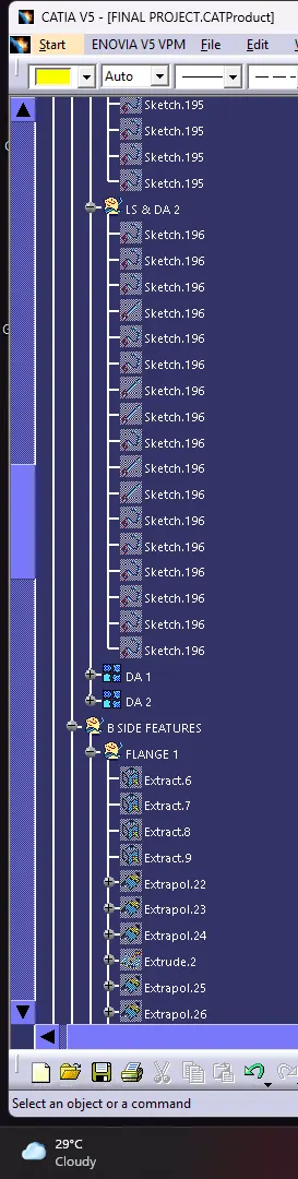
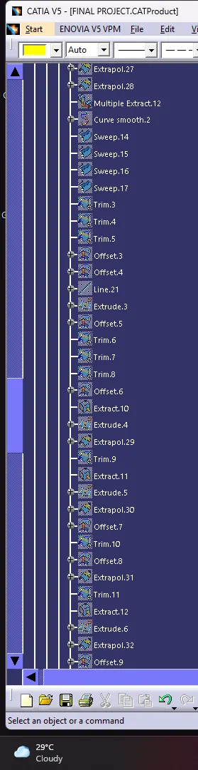
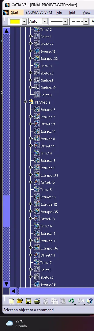
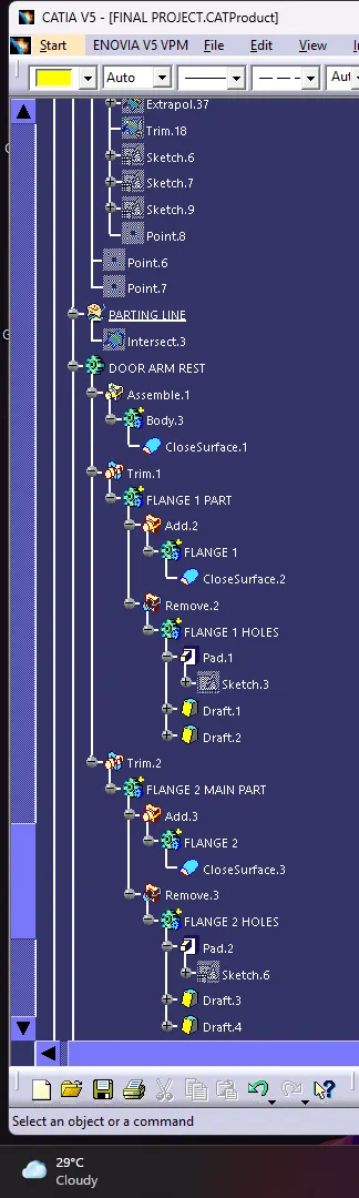
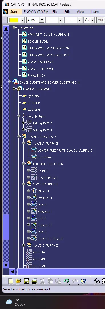
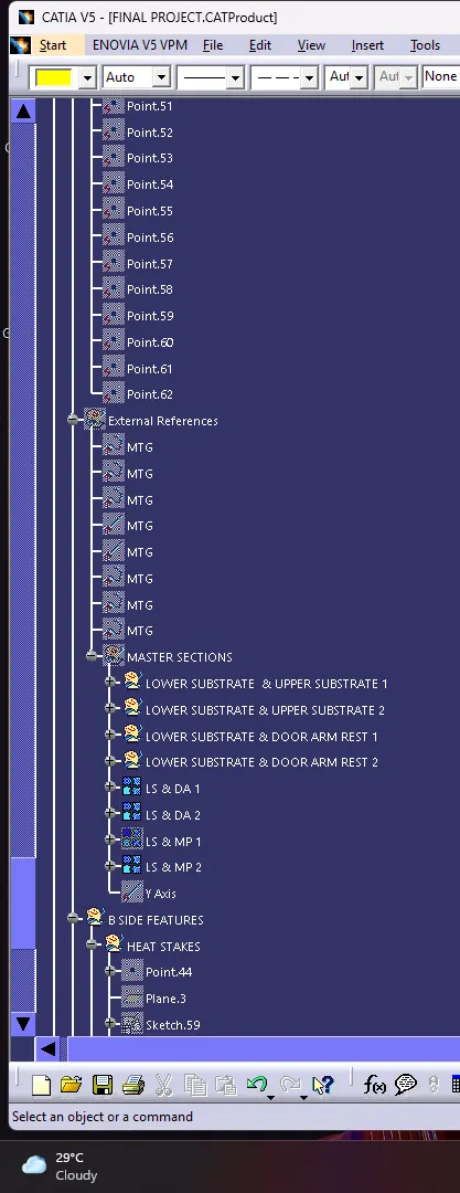
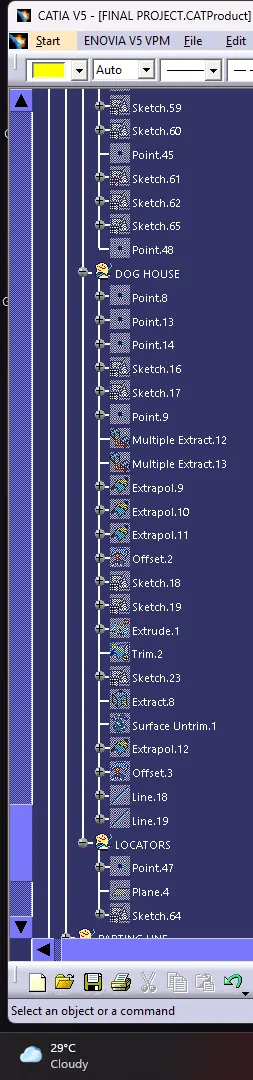
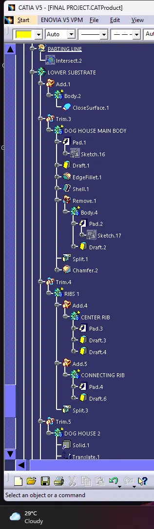
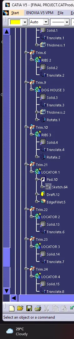
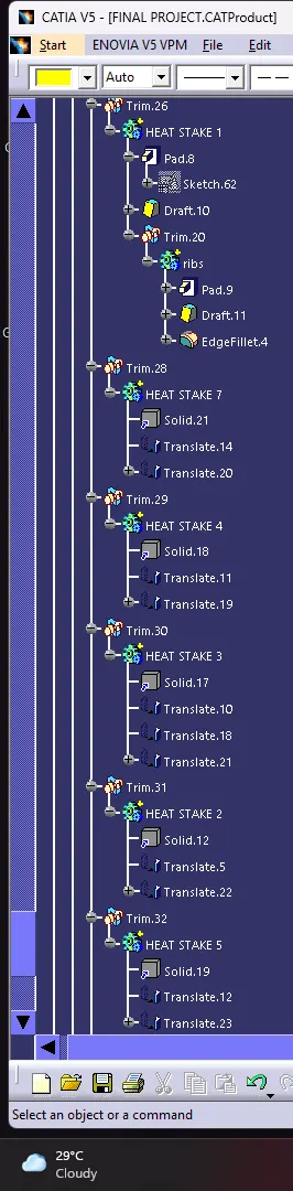
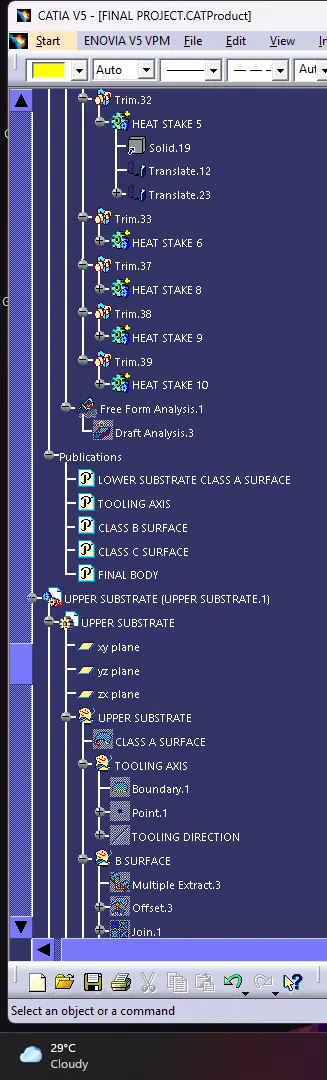
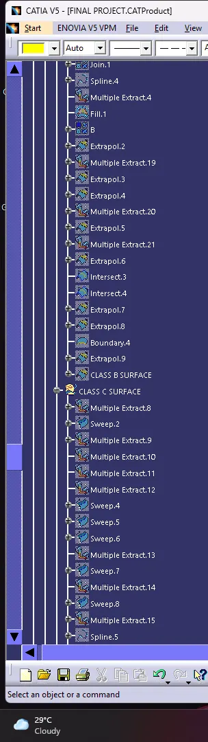
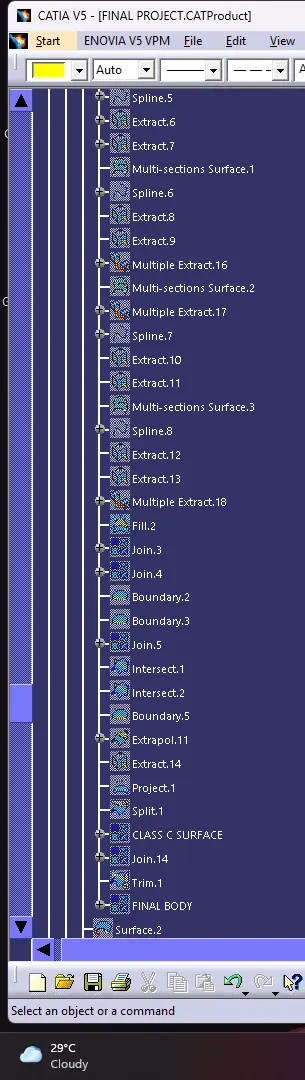
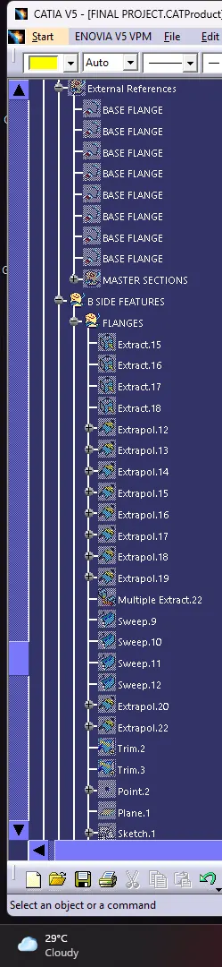
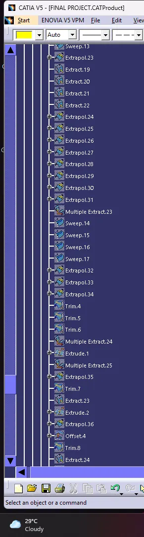
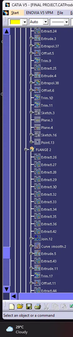
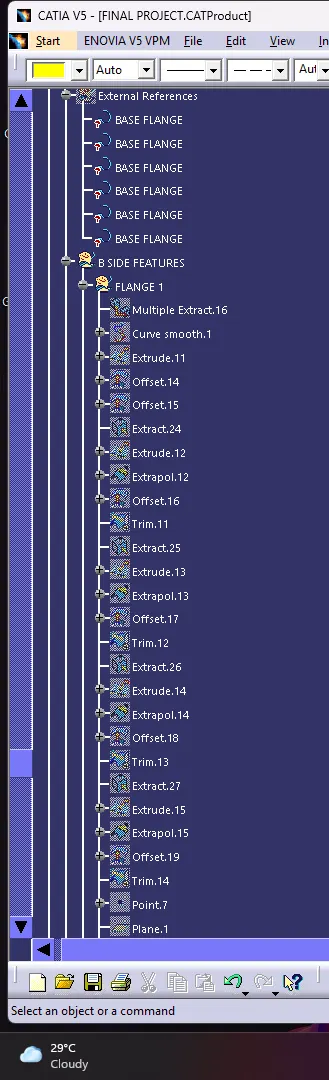
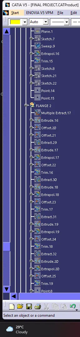
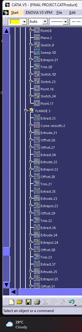
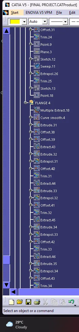
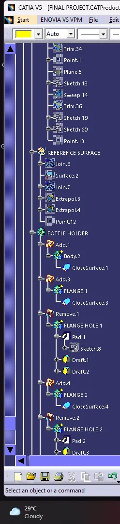
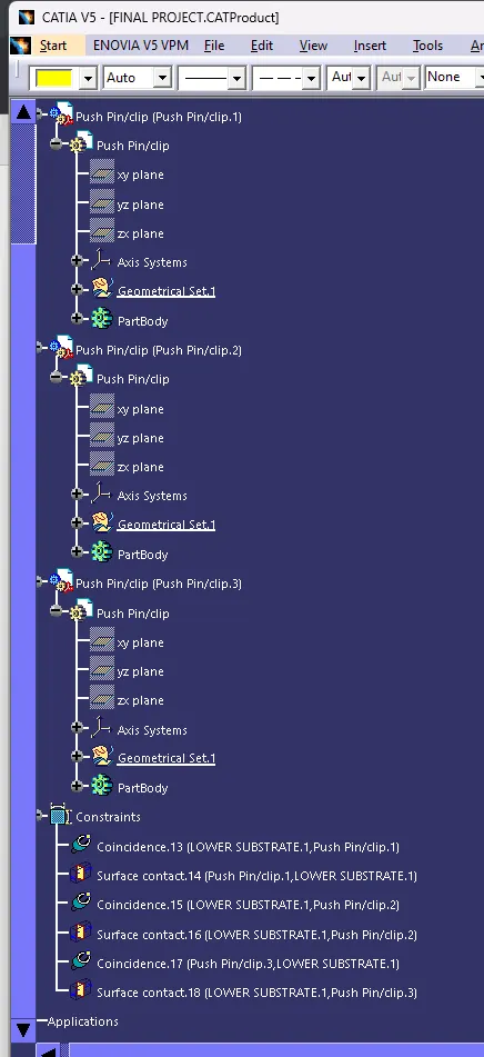
- Ensured Proper Tree Structure
- Geometrical sets should have a proper name based on the sketches present inside of it
- Create thickened part using master section for reference
- Create the mounting features as per design guidelines in the industry and with master sections
- Creating of Draft analysis & Tooling analysis
- Creation of parting lines and check tooling feasibility
INPUT OF CLASS A SURFACE:
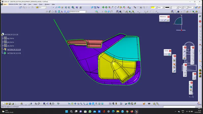
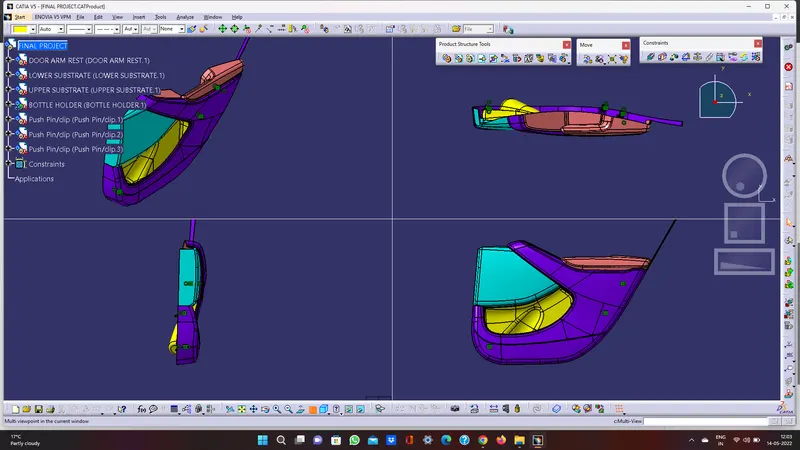
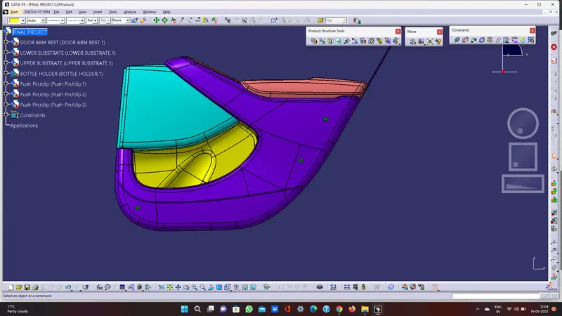
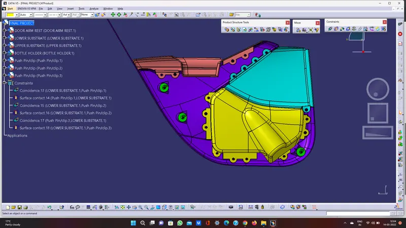
Since the input class A surface is containing four different parts (class A). So class b and c for all the surface has been created in separate cat part. Also performing draft analysis and tooling axis separately. Finally, all the surfaces have assembled in one cat product
CREATION OF TOOLING AXIS - LOWER SUBSTRATE
DRAFT ANLAYSIS
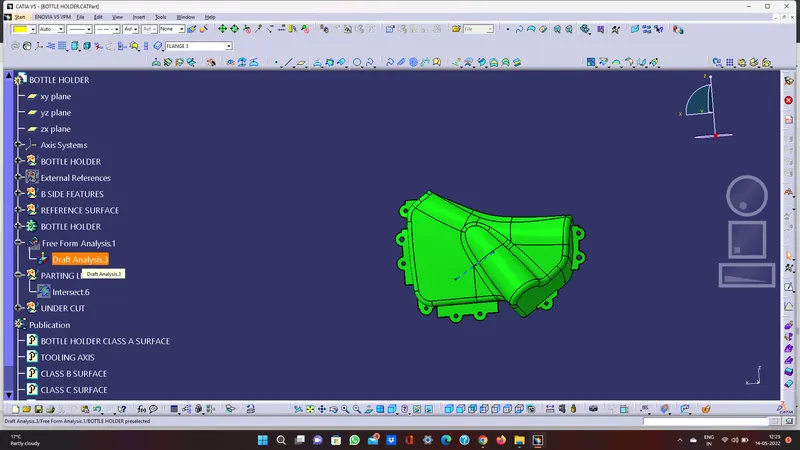
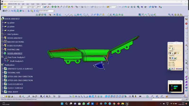
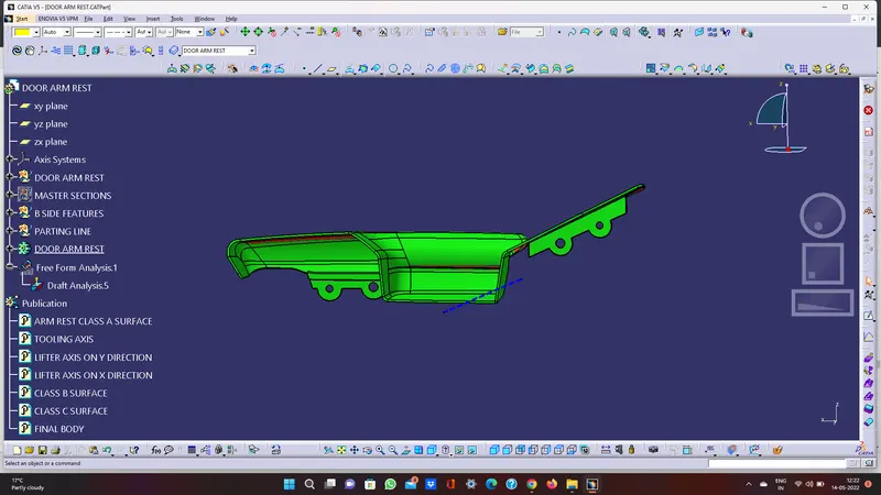
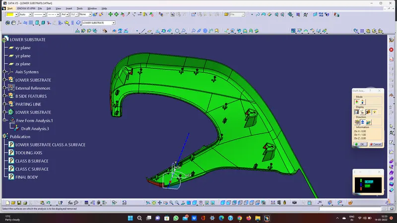
Draft analysis in Catia is a command that is used to detect if the part you drafted will be easily removed from the mould. it is performed based on colour ranges identifying zones on the analysed element.
Most of the industries is using minimum draft angle is 3 degrees.
PROCEDURE
- Check all the boundary whether it has connected or not.
- Check the model visually & choose the best tooling direction which should be easy for draft.
- After analysing the above model, the best tooling axis is y direction.
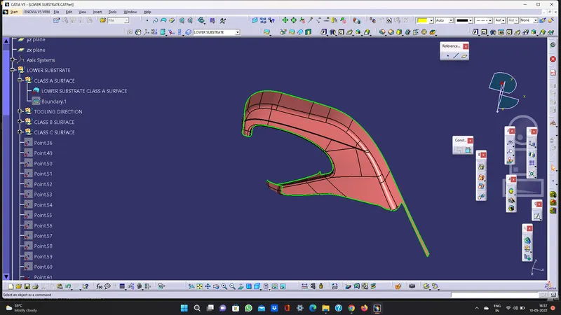
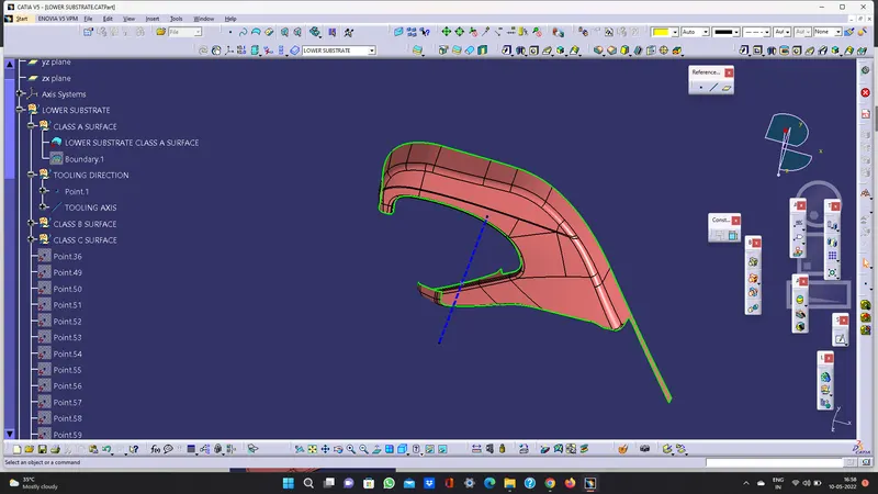
CREATING THE TOOLING AXIS
- Create a point on centre of gravity of part by using measure inertia command and insert a axis system on the point as shown below.
- create a point -direction line parallel to the y axis and named as TOOLING AXIS as shown below.
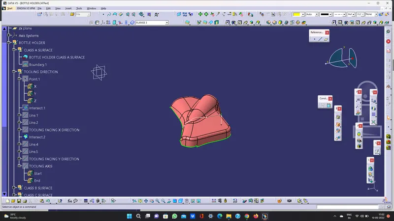
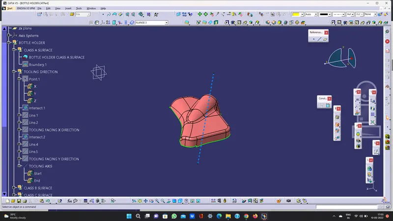
CREATION OF TOOLING AXIS - BOTTLE HOLDER
PROCEDURE
- Check all the boundary whether it has connected or not.
- Check the model visually & choose the best tooling direction which should be easy for draft.
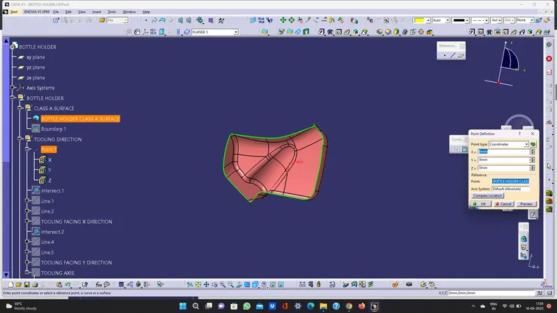
- After analysing the above model, we must create tooling axis on Y
CREATING THE TOOLING AXIS
- Create a point I and insert axis system on the point 1 as shown below.
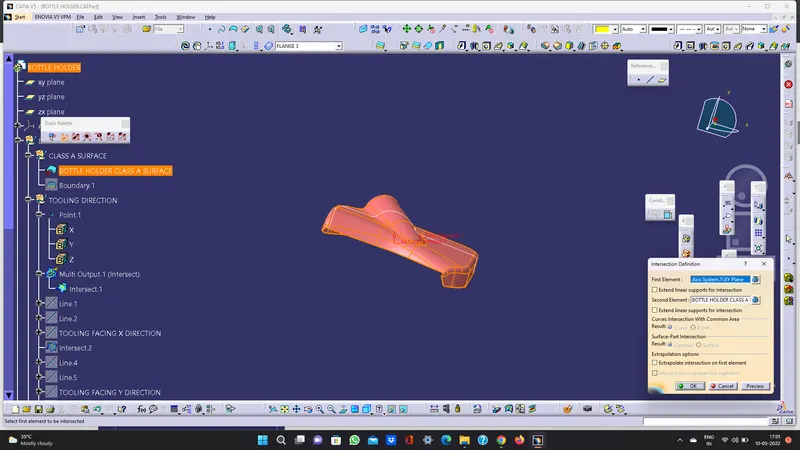
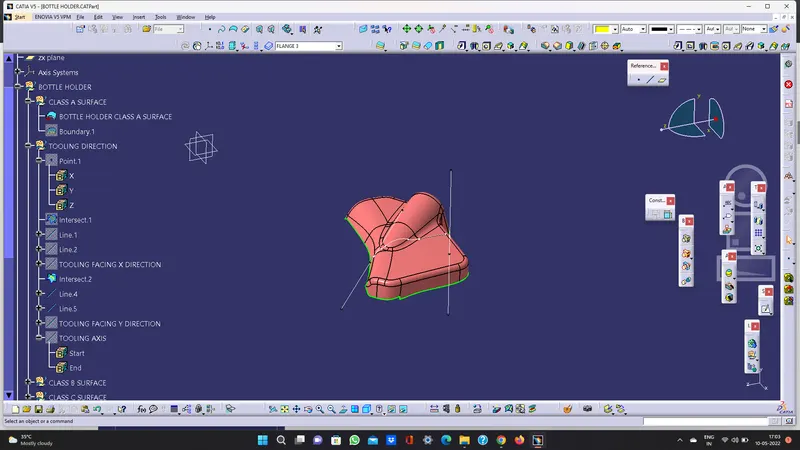
- Create intersection on XY plane for the given surface
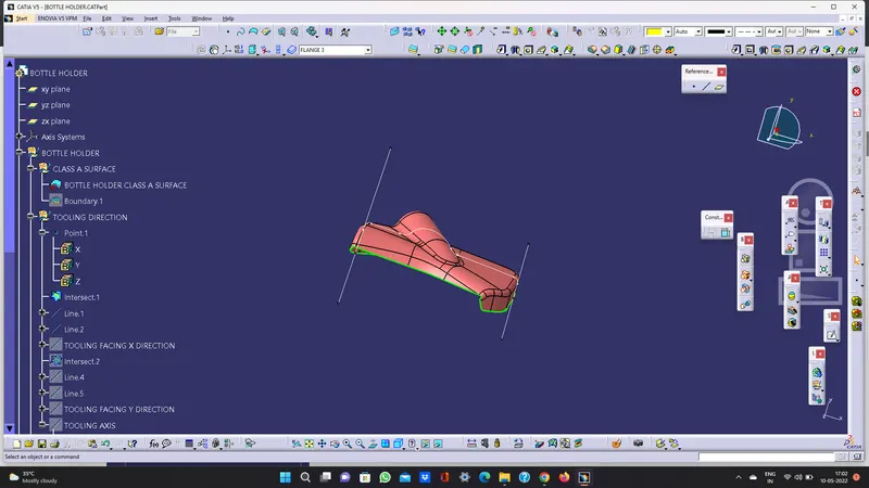
- Create a point-to-point line as shown below
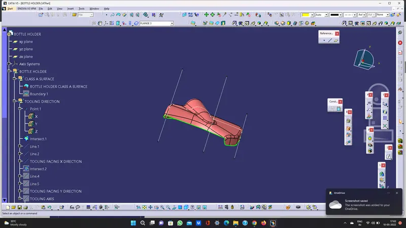
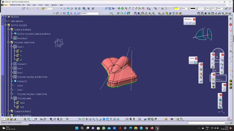
- Add bisecting line as shown below by the reference of two lines created above and named as TOOLING FACING X DRIECTION
- Create intersection on ZY plane for the given surface
- Create a point-to-point line as shown below
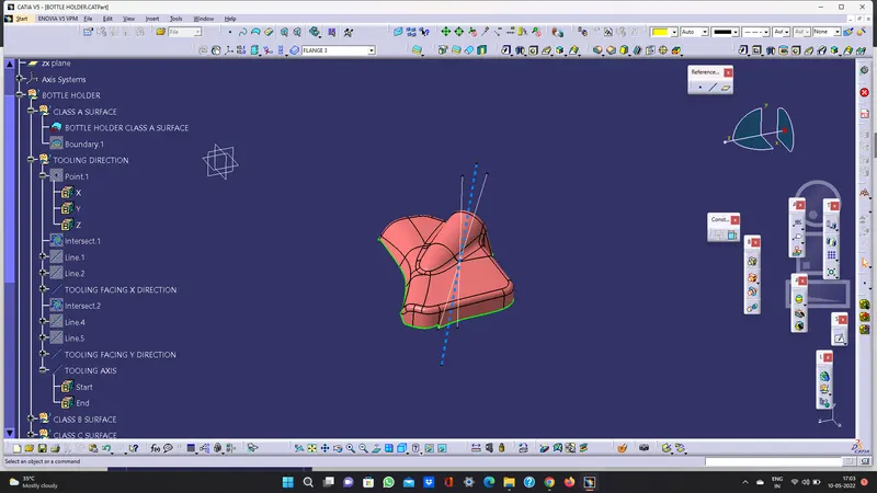
- Add bisecting line as shown below by the reference of two lines created above and named as TOOLING FACING Y DRIECTION
- Add bisecting line by the reference of tooling facing x direction and tooling facing y direction and named as tooling axis.
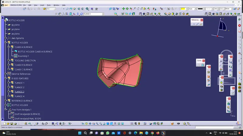
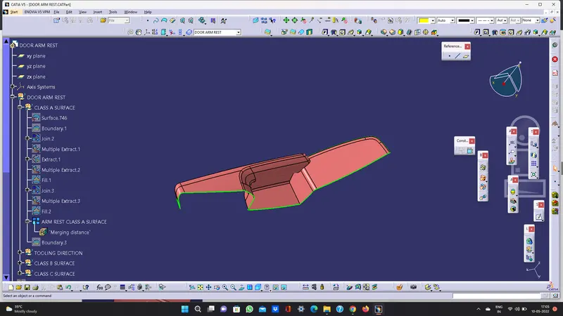
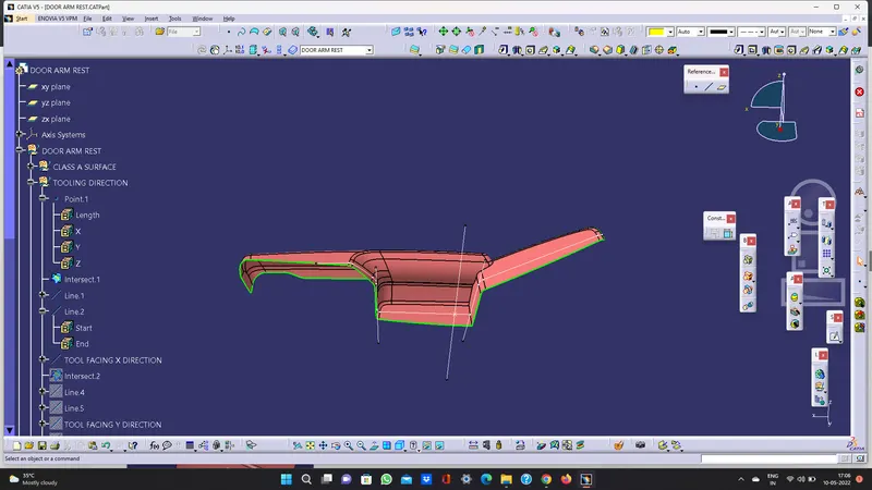
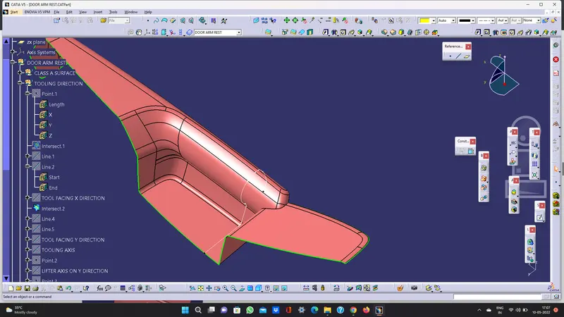
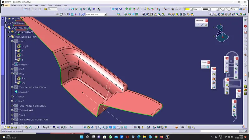
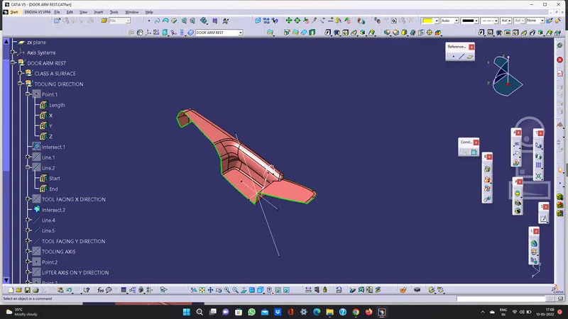
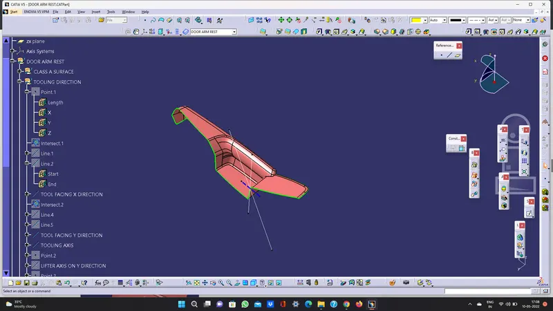
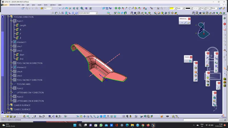
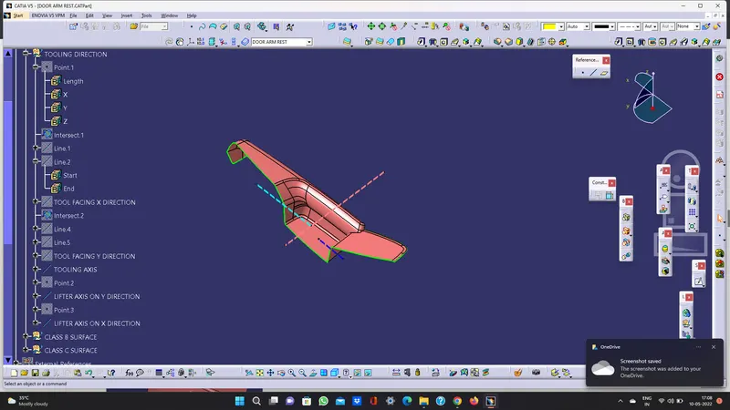
CREATION OF TOOLING AXIS - ARMREST
PROCEDURE
- Check all the boundary whether it has connected or not.
. Check the model visually & choose the best tooling direction which should be easy for draft.
- After analysing the above model, there is a chance for undercut when we consider tooling axis from z.so we have to create tooling axis on x, y and also z
CREATING THE TOOLING AXIS
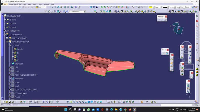
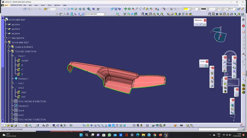
- Create a point and insert axis system on the point 1 as shown below
- Create intersection on ZX plane for the given surface
- Create a point-to-point line as shown below
- Add bisecting line as shown below by the reference of two lines created above and named as TOOLING FACING X DRIECTION
- Create intersection on ZY plane for the given surface
- Create a point-to-point line as shown below.
- Add bisecting line as shown below by the reference of two lines created above and named as TOOLING FACING Y DRIECTION
- Add bisecting line by the reference of tooling facing x direction and tooling facing y direction and named as tooling axis
CREATION OF SIDE TOOLING AXIS Y
- Create a point on surface and create a line using point direction, use direction as y axis.
- Drag a compass and place it on axis that we created. Adjust the compass till we get correct view. lock the orientation of the compass.
- Modify the above line by changing the direction along compass
CREATION OF SIDE TOOLING AXIS X
- Create a point on surface and create a line using point direction, use direction as y axis.
- Drag a compass and place it on axis that we created. Adjust the compass till we get correct view. lock the orientation of the compass.
- Modify the above line by changing the direction along compass
CREATION OF TOOLING AXIS - UPPER SUBSTRATE
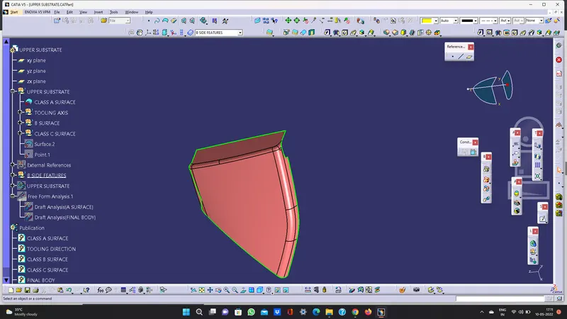
PROCEDURE
- Check all the boundary whether it has connected or not. Check the model visually & choose the best tooling direction which should be easy for draft.
- After analysing the above model, the best tooling axis is y direction.
CREATING THE TOOLING AXIS
- Create a point on centre of gravity of part by using measure inertia command and insert an axis system on the point as shown below. Create a point -direction line parallel to the y axis and named as TOOLING AXIS as shown below
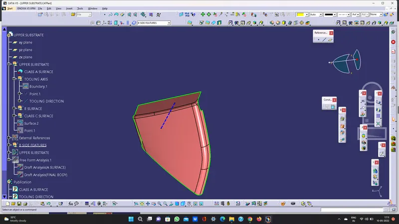
PERFORMING DRAFT ANALYSIS ON MODEL
- To perform draft analysis open, customize view parameters and choose the material.
- Insert a feature draft analysis by following these commands
insert analysis feature draft analysis
- Align the compass on tooling axis that we created
- Open the colour scale and enter the value is 3 deg.
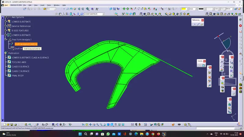
- If the whole body is green that all the faces is greater angle than the provided angle
DRAFT ANALYSIS REPORT OF CLASS A - UPPER SUBSTRATE:
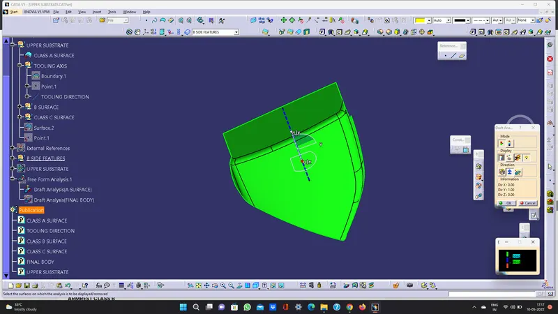
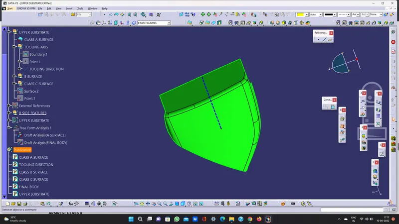
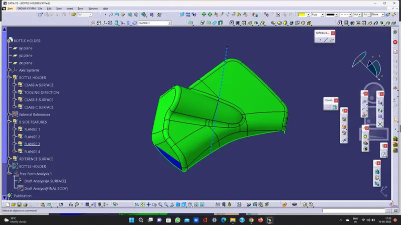
DRAFT ANALYSIS REPORT OF CLASS A - BOTTLE HOLDER:
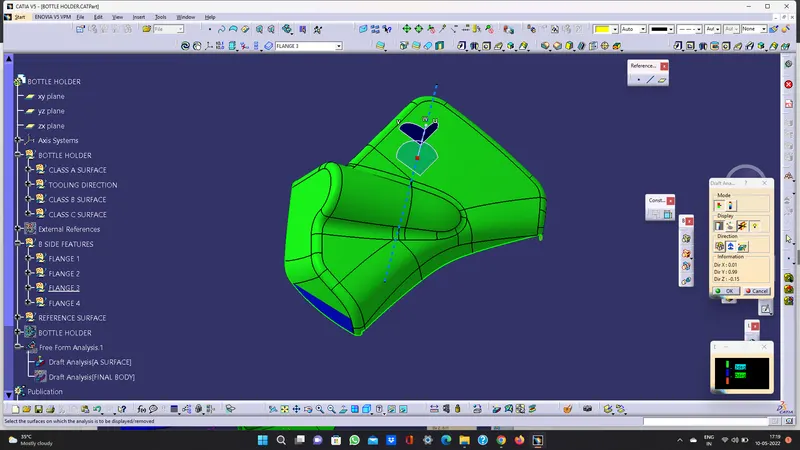
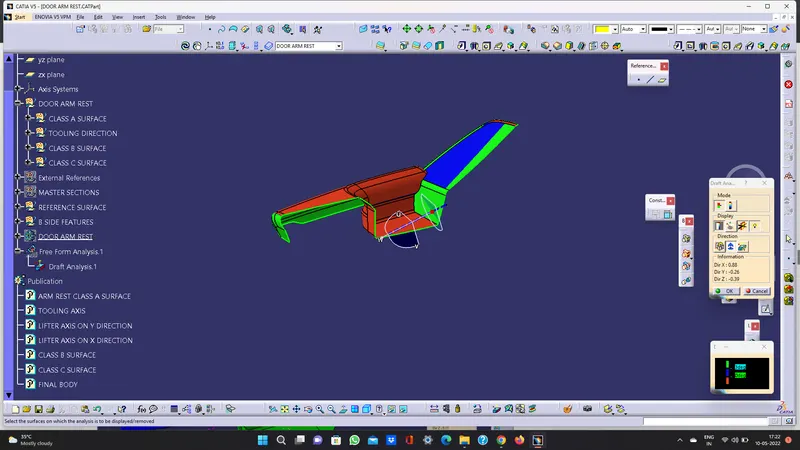
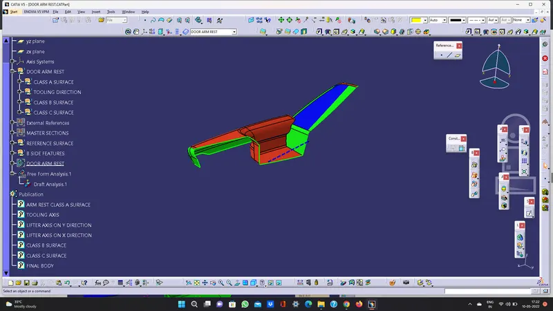
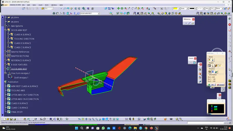
DRAFT ANALYSIS REPORT OF CLASS A – ARM REST:
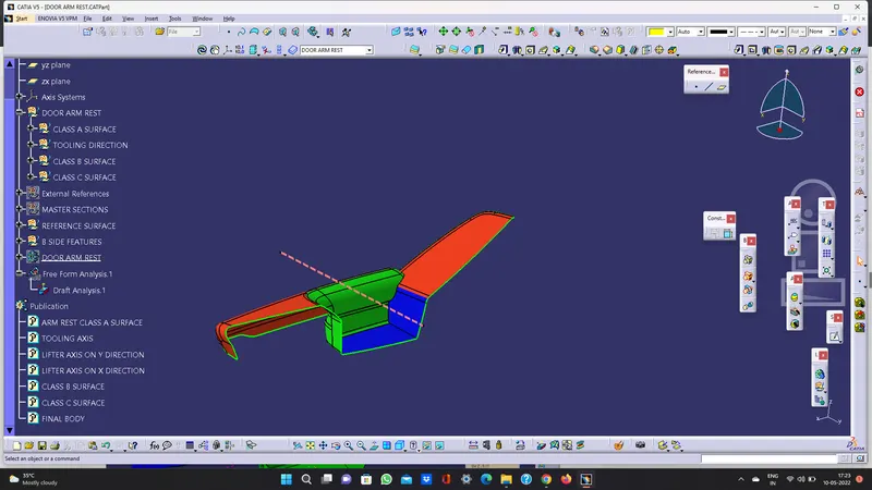
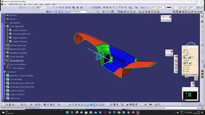
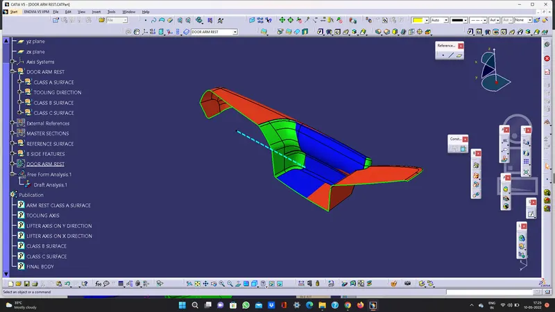
DRAFT ANALYSIS REPORT OF CLASS A - LOWER SUBSTRATE:
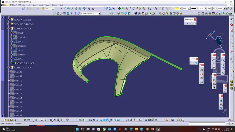
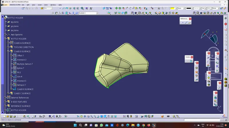
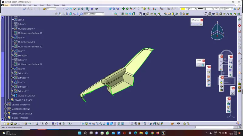
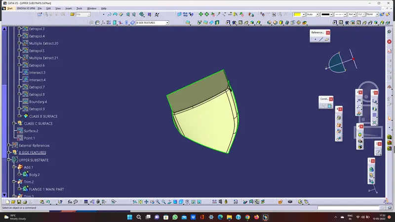
CREATION OF CLASS B SURFACE:
• Insert a new geometrical set. Measure the value of thickness in master section. The value is 2.5mm.
- Offset the class A surface to 2.5mm.
- Check all the sub elements are formed if not try to fix it locally.
LOWER SUBSTRATE CLASS B
BOTTLE HOLDER CLASS B
ARMREST CLASS B
UPPER SUBSTRATE CLASS B
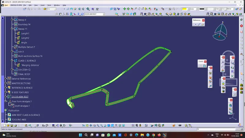
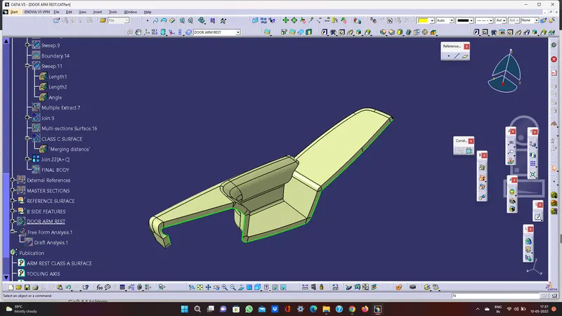
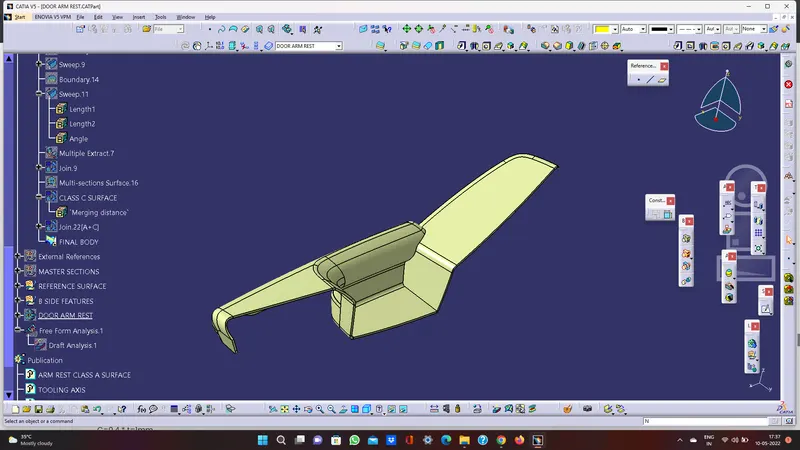
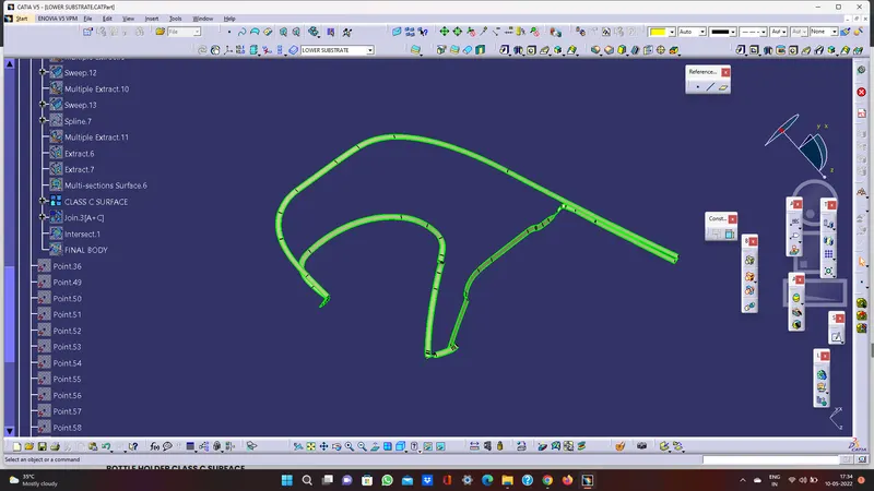
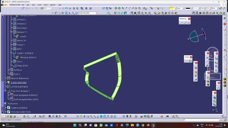
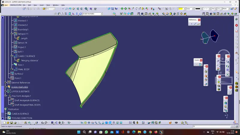
CREATION OF CLASS C SURFACE
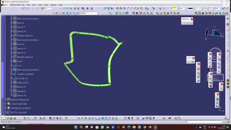
- Analyse the class A once where the sweep is easier to create towards tooling direction.
- Create a boundary using limitation points wherever possible for sweep.
- Sweep the above boundaries for industrial standard 3 degrees towards tooling axis.
- Now Create the c surface by using multi section solid where the sweep can’t perform.
- Create a point on the curve as shown below and create a line by using point to point line.
- Split both surfaces by using split command.
- Create a boundary by using on the class a surface that is going to perform
Multi section surface
- Join the surfaces by using multi section surface
. By using the same method creating the c surface wherever the sweep is not possible
- After joining all the c surface
- Using the same method create c surfaces for all the parts
DOOR ARM REST CLASS C SURFACE
LOWER SUBSTRATE Class C SURFACE
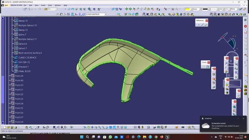
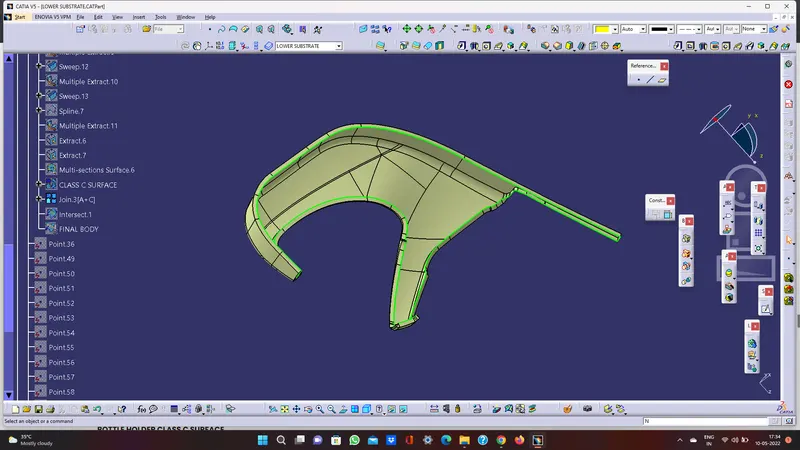
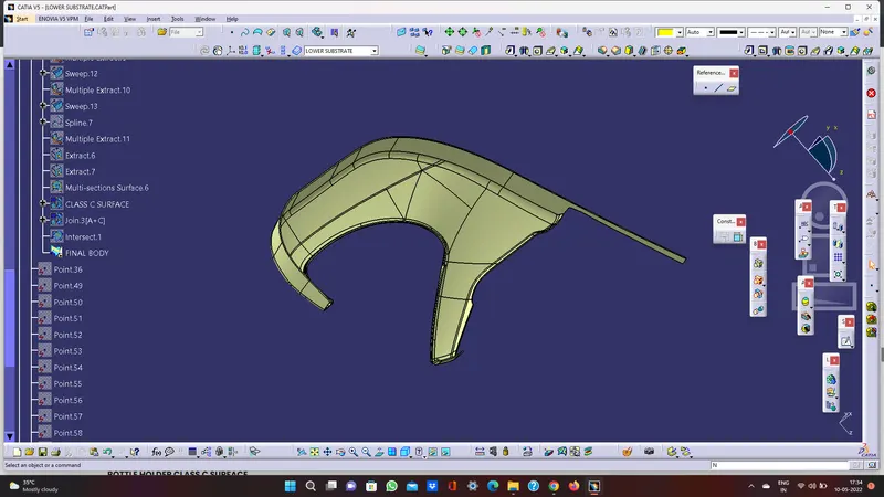
BOTTLE HOLDER CLASS C SURFACE
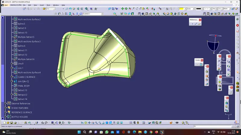
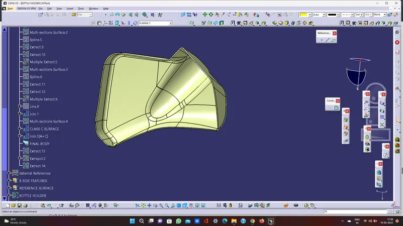
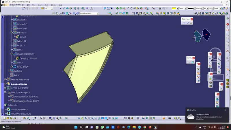
UPPER SUBSTRATE CLASS C SURFACE
CREATION OF B SIDE ATTACHMENT FEATURES
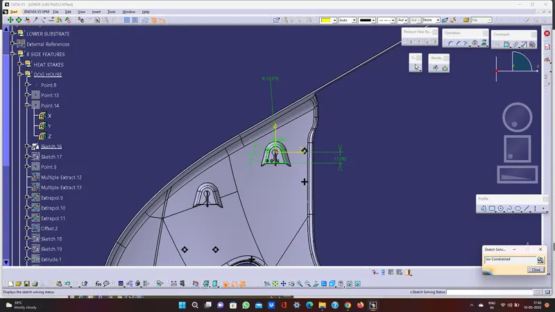
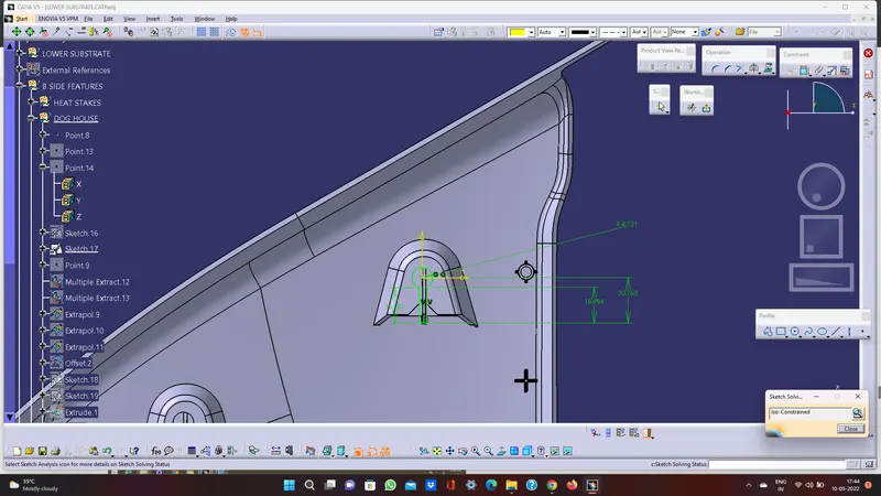
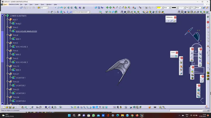
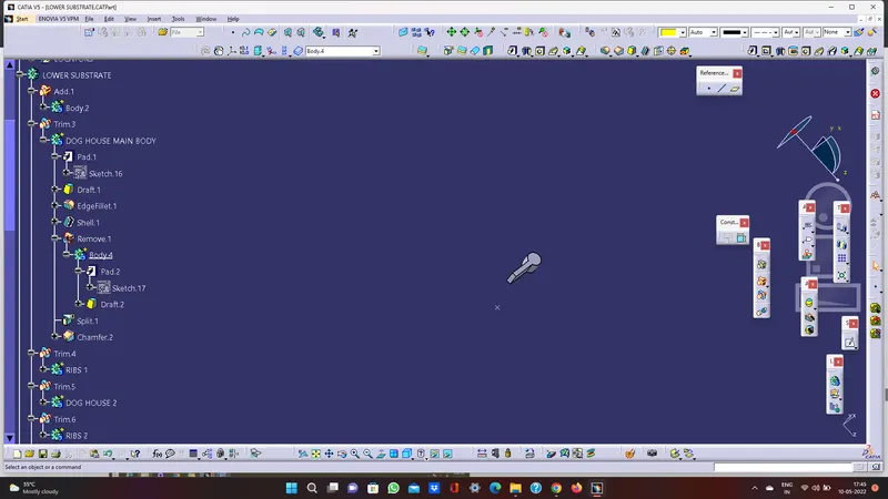
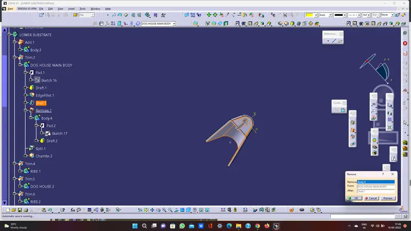
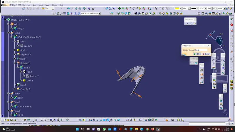
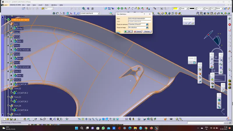
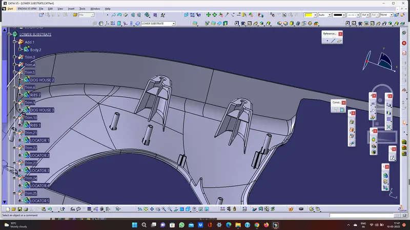
DOGHOUSE
- Extract the surface that we going to create a doghouse
- Insert an axis system. use positioned and drew a doghouse sketch
- Sweep the sketch to 1.5 degree on the direction of main tooling axis
- Add thickness to the above sketch of 2.5mm by using thicken surface
Doghouse rule
B=4mm
t=2.5mm
C=0.4 t=1mm
- Extract the sweep and offset to b=4mm and c=1mm on all directions like the below
- Trim the portion to get the required
sketch
- Draft to 5 degrees along second tooling axis
- Add fillet to all faces
- Assemble the doghouse to lower substrate solid
- Translate the doghouse to wherever we need
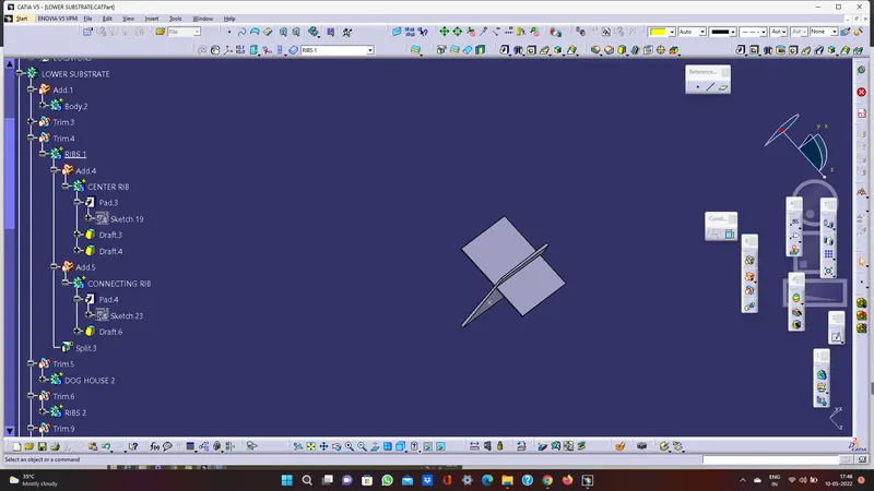
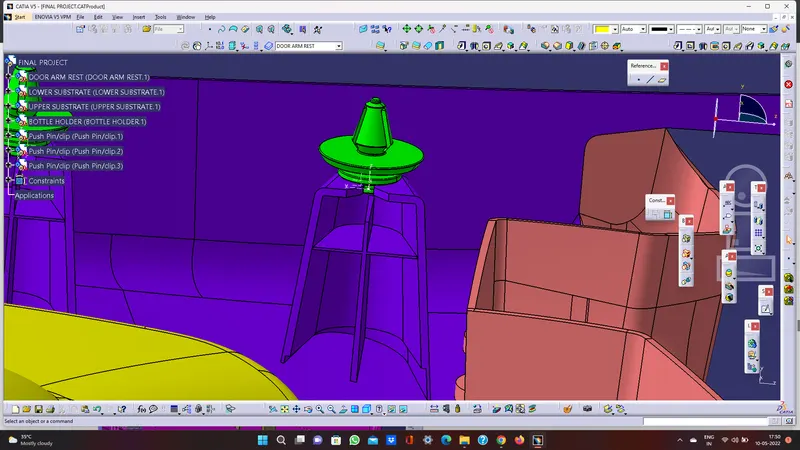
- To place pushpin on the doghouse, create a ribs to doghouse
- Trim the ribs with doghouse

PUSHPIN
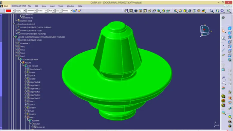
- Draw a sketch of pushpin by using positioned sketch command
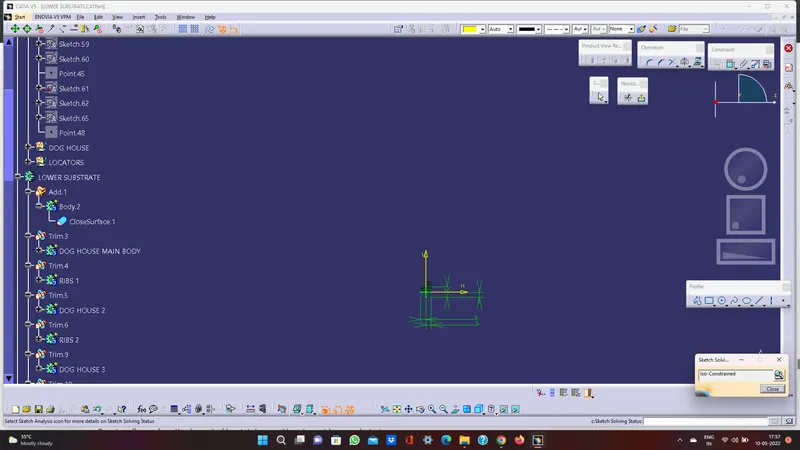
- Ensure that the sketch is iso constrained
- Shaft the sketch to 360 degrees by using shaft command. Add minimum fillets to pushpin. Create a sketch to groove the pushpin for 30 degrees
- Use circular pattern command for groove
- Otherwise insert a push pin clip into assembly design if already given that.
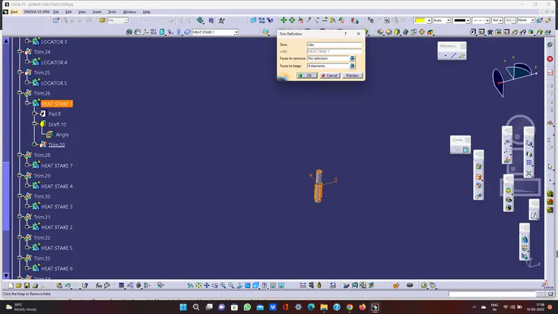
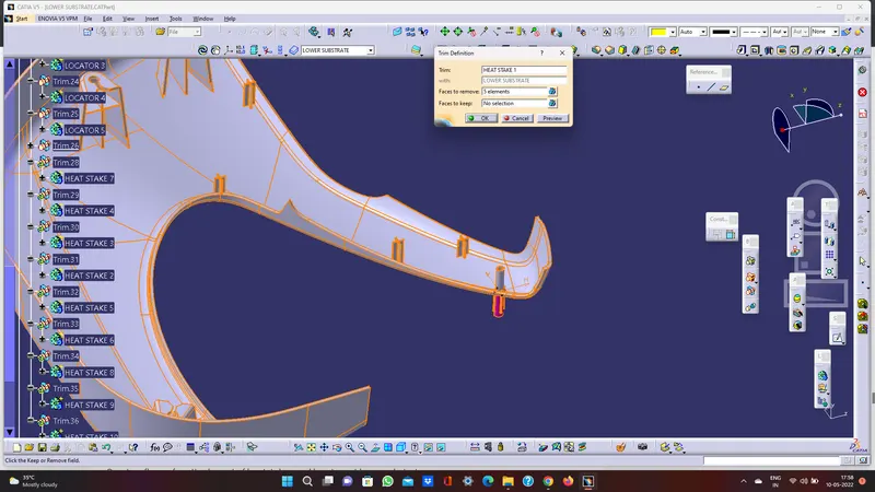
HEAT STAKES
Heat stakes is known as thermoplastic staking is the process of joining two dissimilar metals together
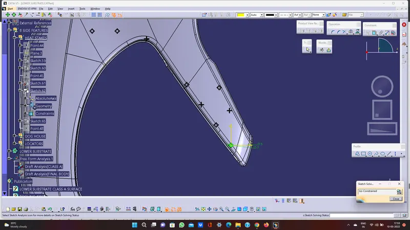
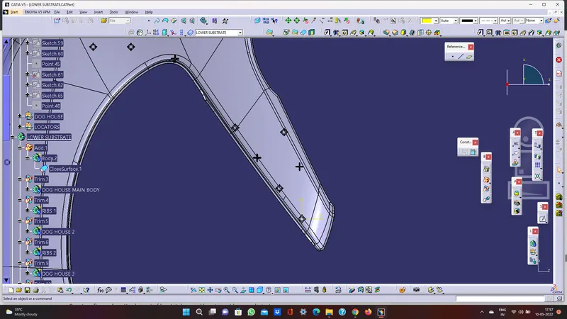
- Extract the surface that we going to create heat stake
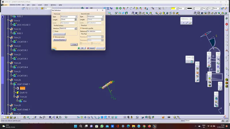
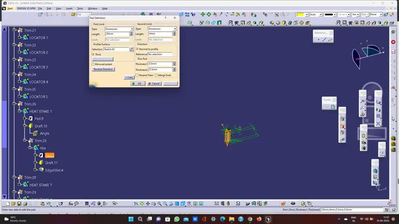
- Use positioned sketch and draw a heat stakes sketch. Use pad commands for the sketch to till we required.
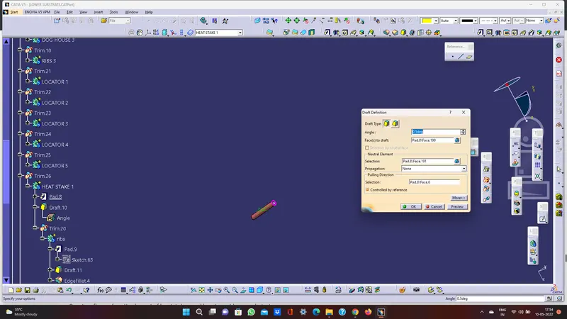
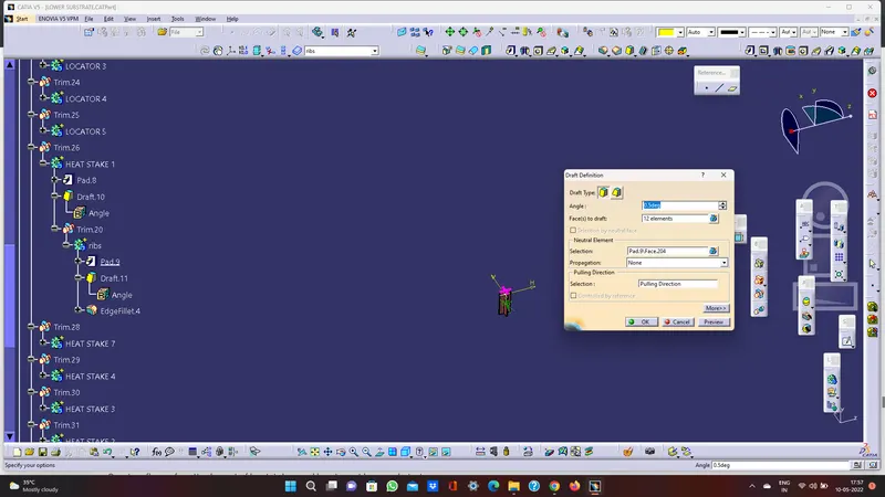
- Draft the stakes minimum of 0.5 degree
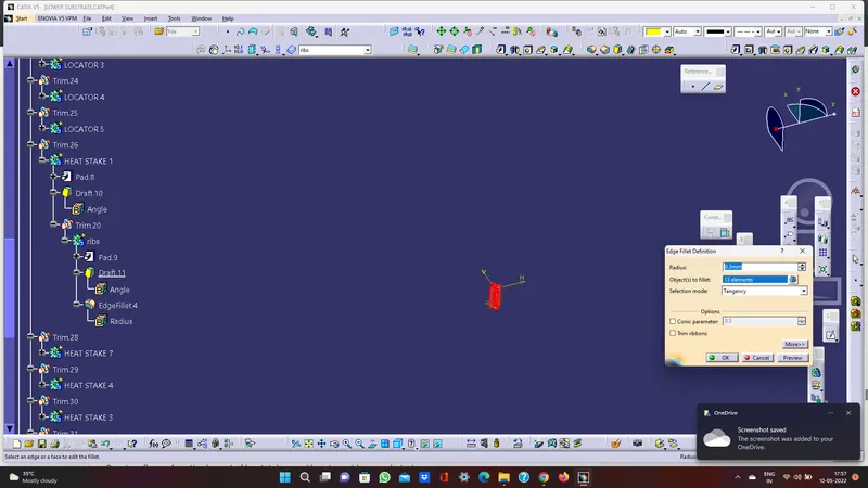
- Add fillet 0.5mm o all faces
- Assemble the heat stake to lower substrate solid
- Maintain a 50mm minimum between two heat stakes
- Translate the heat stakes to wherever we need
- Trim all heat stakes with lower substrate solid
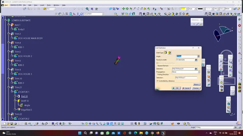
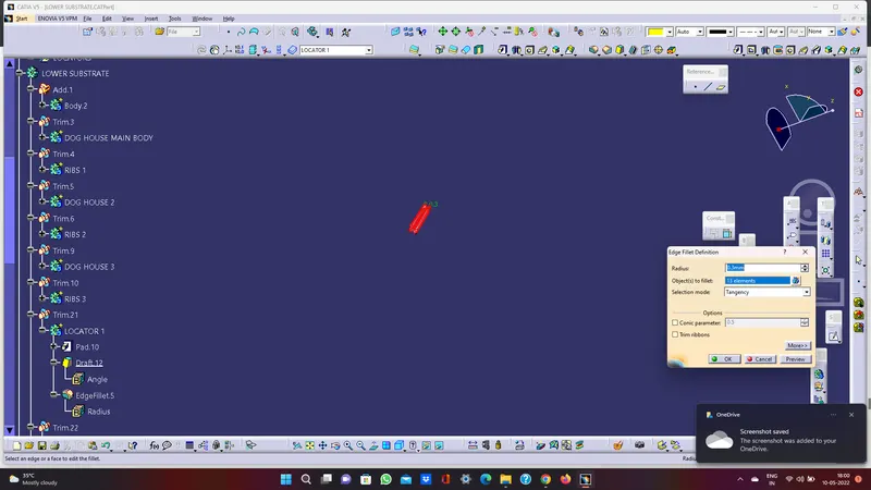
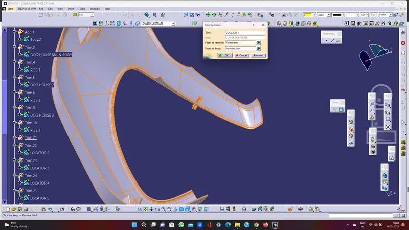
LOCATOR
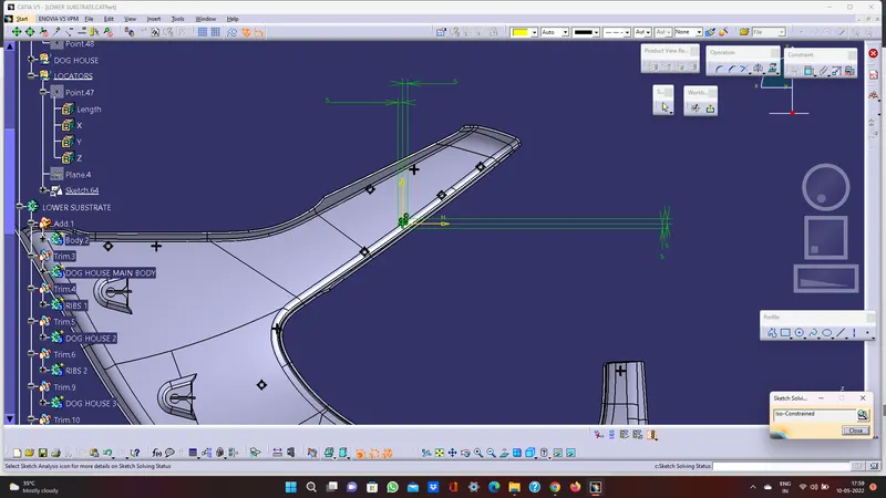
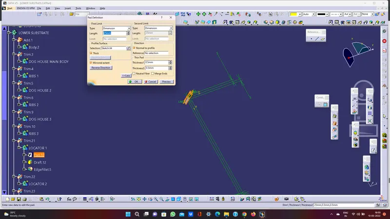
- Extract the surface that we going to create locator
- Use positioned sketch and draw a locator sketch. Use pad commands for the sketch to till we required
- Draft the locator for minimum of 0.5 degree
- Add fillet 0.3 to 0.5mm for all faces
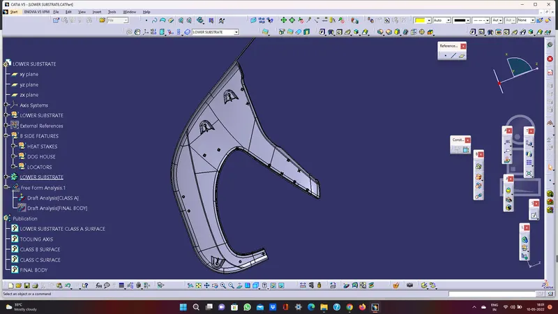
- Assemble the locator to lower substrate solid. Maintain a 50mm minimum between two locators
- Translate the locator to wherever we need
- Trim all heat stakes with lower substrate solid
- Maintain a height more than heat stake
FLANGE
Create a flange for attachment of heat stakes and locators at lower substrate
WEIGHT OF THE COMPONENT
Apply material plastic to the product
- Use measure command to calculate the weight of product
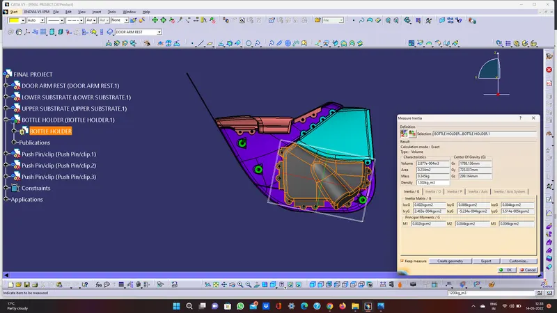
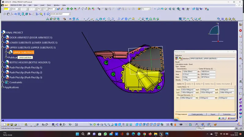
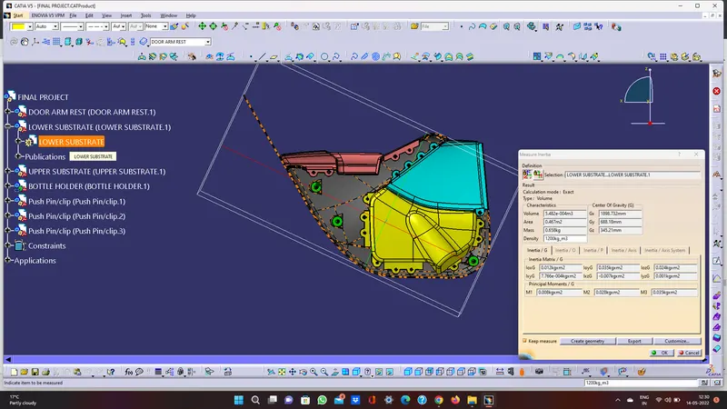
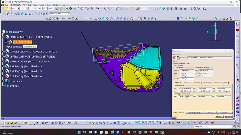
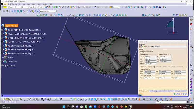
CALCUALTION
Lower substrate=0.658kg
Bottle holder=0.345kg
Arm rest=0.22kg
Upper substrate=0.188kg
The total weight of the product is =1.427kg
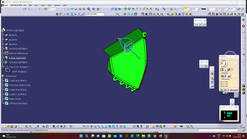
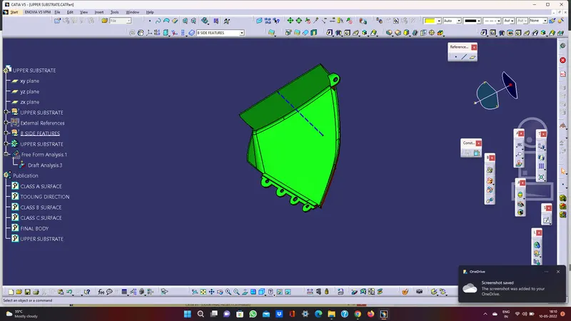
DRAFT ANALYSIS REPORT OF UPPER SUBSTRATE
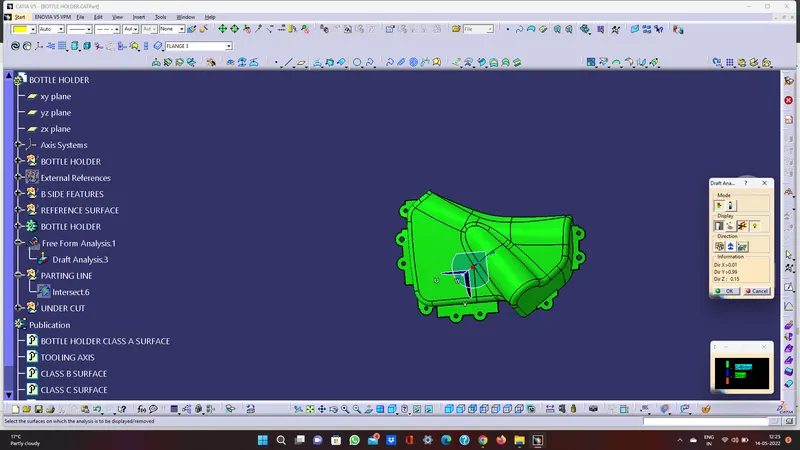
DRAFT ANALYSIS REPORT OF BOTTLE HOLDER
DRAFT ANALYSIS REPORT OF ARM REST
DRAFT ANALYSIS REPORT OF LOWER SUBSTRATE
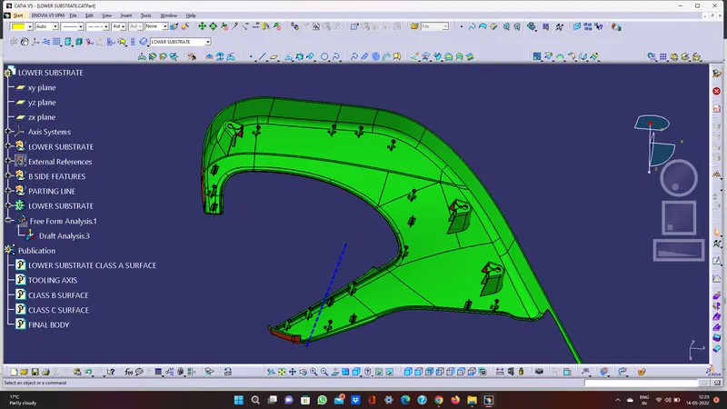
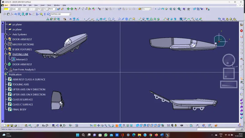
CREATION OF PARTING LINE
Parting line is used to the differentiate between core and cavity
NOTE = THE PARTING LINE BELOW IS CREATED WITHOUT ATTACHMENT
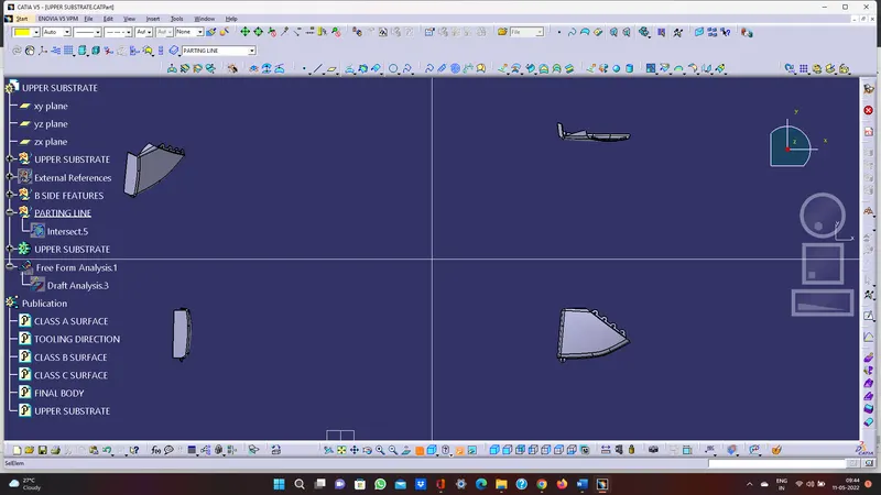
TREE STRUCTURE:
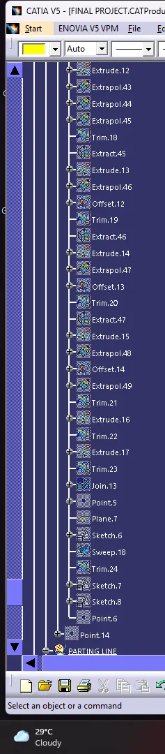
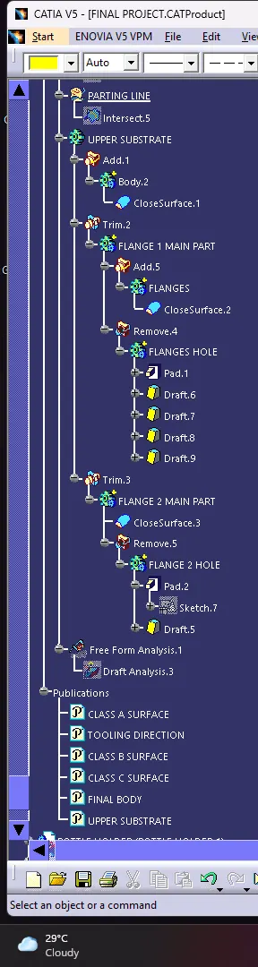
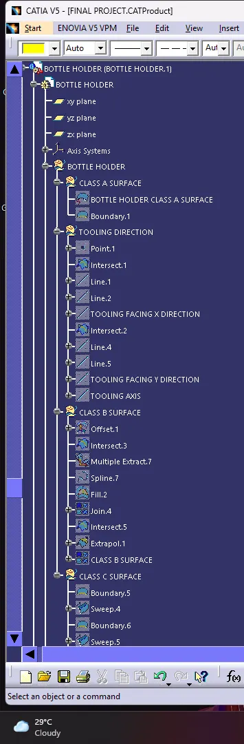
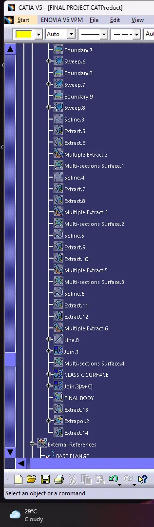
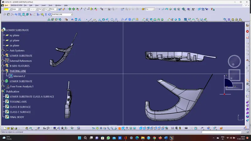
MODELS IN VARIOUS ORIENTATIONS:
LOWER SUBSTRATE
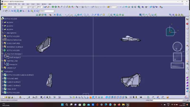
BOTTLE HOLDER
ARM REST
UPPER SUBSTRATE
DOOR INTERIOR
CONCLUSION:
Thus, the door interior part has been created from the inputs of class A surface along with master section by following the design rules followed in tier 1 and OEM industries in Catia v5.