Photo Realistic Rendering
Modelling of American chopper on Solidworks
BANAVASI VENKATESWARAREDDY
Introduction:
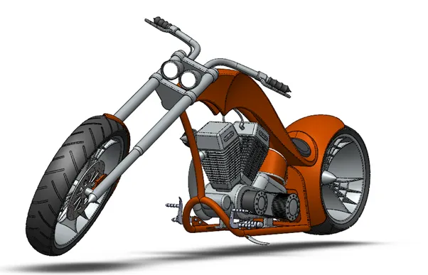
In this project we are to learn the entire modeling of an American chopper on solid works and solid works visualize.
The different components of the American chopper we deal with are:
- Transmission Belt
- Kickstand
- Front Fender
- Rear Fender
- Chain
- Oil Tank
- Pedal
- Front Wheel
- Rear Wheel
10.Front Fork
11.Chassis
12.Engine
13.Gas Tank
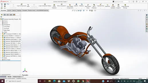
After designing the part components, we have worked upon the assembly and the photo rendering of the chopper which gives it a complete and realistic view.
Design approach:
Let we start with transmission belt and end with rendering as shown in below flow chart.
TRANSMISSION BELT

KICKSTAND

FRONT FENDER  REAR FENDER

OIL TANK

PEDAL  CHAIN LINK



FRONT WHEEL REAR WHEEL
CHASSIS

GASTANK ENGINE
ASSEMBLY
RENDERING
1.Transmission Belt:
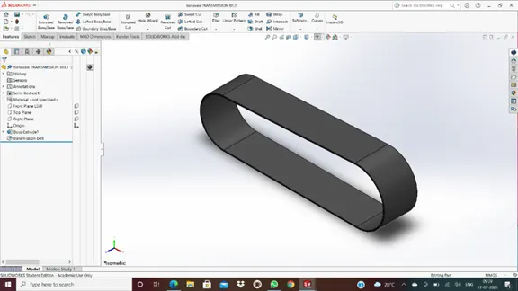
In this modelling of transmission belt, we will know that 2D sketches, quick features, extrude, fillets, appearance.
DESCRIPTION:
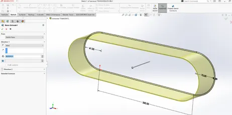
- EXTRUDE BOSS/BASE
To create an extruded boss: 1) Sketch a profile for the extruded boss. 2) Select Extruded Boss/Base on the Features toolbar or select Insert, Base, Extrude on the menu bar. Use the spin buttons beside the depth text box to change the value, or type in the value in the text box.
- FILLETS
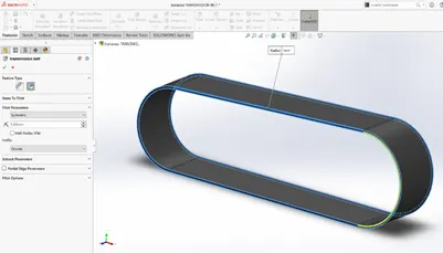
To create fillets:
- Click Fillet on the Features toolbar, or click Insert, Features, Fillet/Round.
- Set the Property Manager options. For constant radius fillets only, you can use the Fillet Expert to add or modify fillets and to manage fillet corners.
- Click OK.
MODELLING OF TRANSMISSION BELT:
2.kickstand:
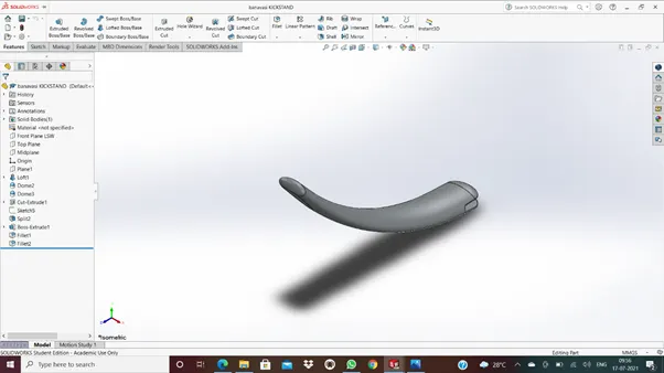
In this modelling of kickstand, we will know the quick features are extrude cut, split, dome, fillet, boss extrude. already we know that how to use the boss extrude and fillet. Now we can show the other features.
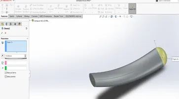
- DOME
Click Dome on the Features toolbar, or click Insert > Features > Dome. Select one or more planar or non-planar faces. Set a value for the distance by which the dome expands. Click to create a concave dome (default is convex).
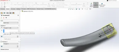
- CUT EXTRUDE:
You can also go to the toolbar and click Insert -> Cut -> Extrude to pull up the Cut-Extrude Feature menu as well. Once the Extrude menu appears on the left-hand side of your screen, it will prompt you to select a plane or sketch that will be used to create the 3D model feature.
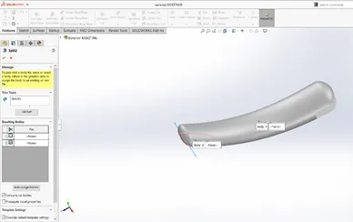
- SPLIT:
Use the Split feature to create multiple parts from an existing part. You can create separate part files, and form an assembly from the new parts. You can split one or more solid or surface bodies. To split a surface, the Trimming Surface must extend past the boundaries of the surface to split.
MODELLING OF KICKSTAND:
3.FRONT FENDER:
In this modelling of front fender split, fillet, revolve boss/base. Already we know how to use the split and fillet feature in last modelling.
- REVOLVE BOSS/BASE:
Revolved Boss or Base is a SolidWorks feature tool which is used to create solid 3D model around an axis. You can revolve the sketch around an axis to add materials to it Create a sketch that contains one or more profiles and a centrelines, line, or edge to use as the axis around which the feature revolves. Click one of the following revolve tools: Revolved Boss/Base (Features toolbar) or Insert > Boss/Base > Revolve. Revolved Cut (Features toolbar) or Insert > Cut > Revolve.
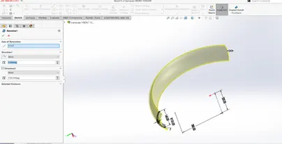
MODELLING OF FRONT FENDER:
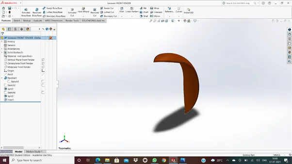
4.REAR FENDER:
In this modelling of rear fender to use the split feature, fillets, revolve boss/base, and also shell feature.
- SHELL:
- Set Thickness to set the thickness of the faces you keep.
- Select one or more faces in the graphics area for Faces to remove.
- Select Shell outward to increase the outside dimensions of the part.
- Select Show preview to display a preview of the shell feature.
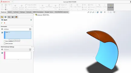
MODELLING OF REAR FENDER:
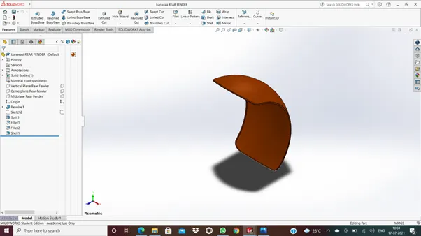
5.chain:
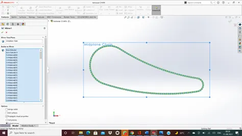
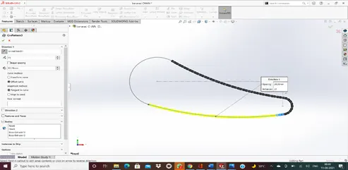
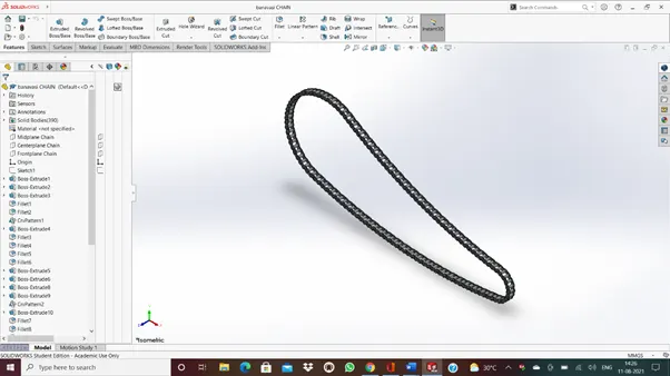
In this modelling of chain, we are used a lot of features, they are boss extrude, fillets, split, crv pattern, and finally mirror.
- MIRROR:
In this post, you will learn how to use the Mirror command in Solidworks. Mirroring is another way that SolidWorks can create a “copy” of an existing object. Additionally, you must choose a plane to mirror parts. In most cases, you will have to create your own plane to have the mirror done the way you need.
- Crv pattern:
- Create a part that includes a feature you want to pattern along a curve.
- Click Curve Driven Pattern (Features toolbar) or Insert > Pattern/Mirror > Curve Driven Pattern.
- In the Property Manager, set the options.
MODELLING OF CHAIN:
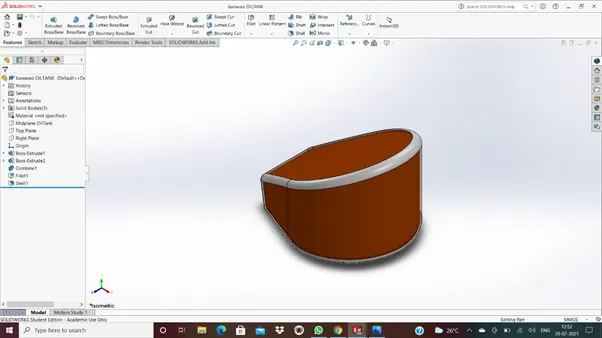
6.OILTANK:
In this modelling of oil tank, we can use the boss extrude, fillets, shell. Already this tool features we know how to use it. Let we know the new feature in this model combine feature.
- Combine: The Combine feature lives under Insert>Features>Combine. The common function allows you to add two bodies together, and keep the area that is common to them. To use this feature, we will select the common button, and then under Bodies to Combine, select the two bodies.
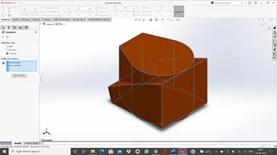
MODELLING OF OILTANK:
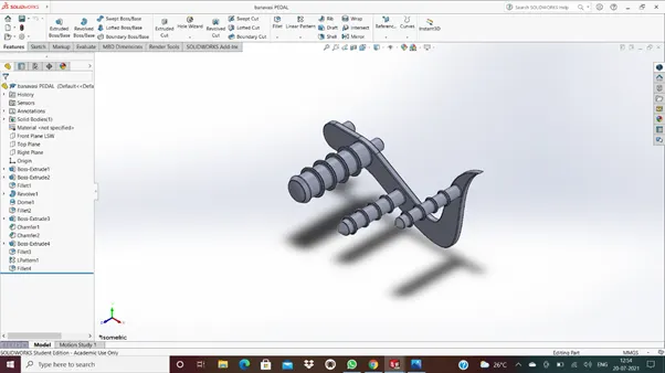
7.PEDAL:
The features used in this part model are boss extrude, revolve boss, fillet, chamfer, L pattern, dome.
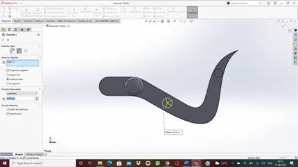
- CHAMFER:
Click Chamfer (Features toolbar) or Insert > Features > Chamfer. Under Chamfer Parameters, select an item and set parameters.
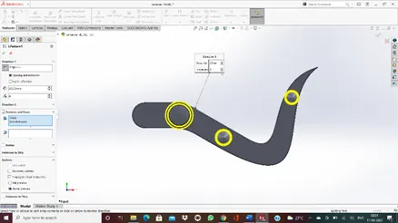
- LINEAR PATTERN:
- Click Linear Component Pattern (Assembly toolbar) or Insert > Component Pattern > Linear Pattern.
- In the Property Manager, specify options under Direction 1.
- Repeat for Direction 2 for a bidirectional pattern.
- Click in Components to Pattern, then select the seed components.
MODELLING OF PEDAL:
8.FRONT WHEEL:
In this part model, the tool features are cut extrude, boss extrude, revolve boss, fillet, chamfer, circular pattern.
- CIRCULAR PATTERN:
Create one or more features to replicate.
Click Circular Pattern (Features toolbar) or Insert > Pattern/Mirror > Circular Pattern.
Set the Property Manager options.
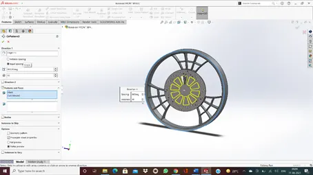
MODELLING OF FRONT WHEEL:
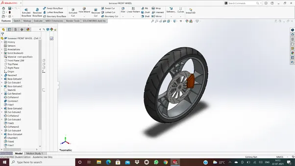
9.REAR WHEEL:
In this part model as same as front wheel features tool are used.
MODELLING OF REAR WHEEL:
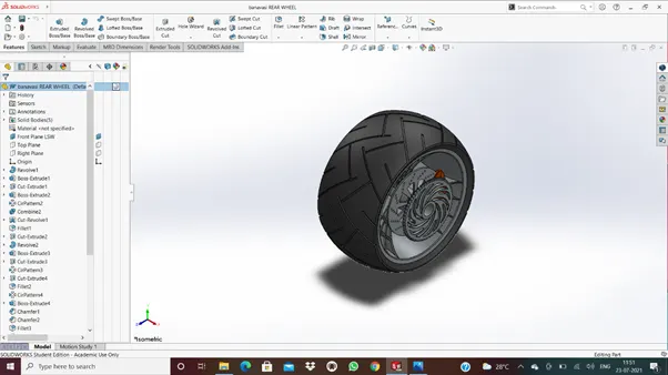
10.FRONT FORK:
In this part model we know the new features tools are projected curves, reference geometry, sweep boss/cut.
REFERENCE GEOMETRY:
Reference geometry defines the shape or form of a surface or a solid. Reference geometry includes items such as planes, axes, coordinate systems, and points. You can use reference geometry in the creation of several kinds of features.
For example: Planes are used in lofts and sweeps. An axis is used in a circular pattern.
PROJECTED CURVE:
You can project a sketched curve onto a model face to create a 3D curve. You can also create a 3D curve that represents the intersection of two extruded surfaces generated by creating sketches on two intersecting planes. You can create multiple closed or open-contour projected curves from a single sketch. You can also use 3D sketches as input for the Projected Curve tool. Note: The Projected Curve tool does not support projections of intersecting curves.
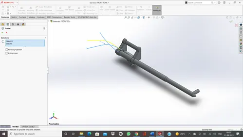
- SWEEP BOSS/CUT:
- Open a part that has either a closed profile sketch and a sketch path, or a part with a sketch line, edge or curve on the model that you can specify as a path. For a solid profile, open a part that has a tool body as the profile and a sketch path to follow.
- Click Swept Cut (Features toolbar).
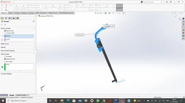
MODELLING OF FRONT FORK:
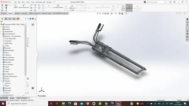
11.CHASIS:
In this part model we have to use the features are boss extrude, fillets, chamfers, sweep, dome, split, revolve, mirror, combine.
MODELLING OF CHASSIS:
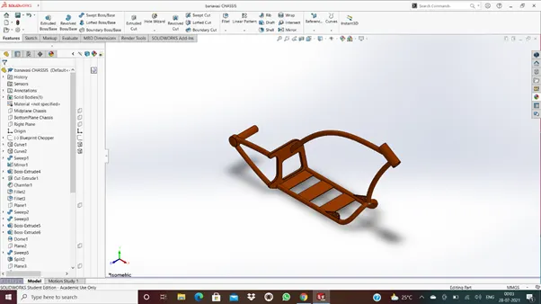
12.ENGINE:
In this part model, newly feature is composite curve. It means the combination of two or more curves.
MODELLING OF ENGINE:
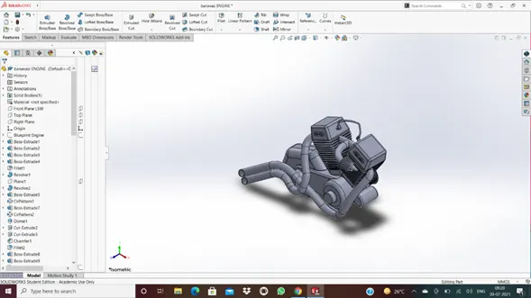
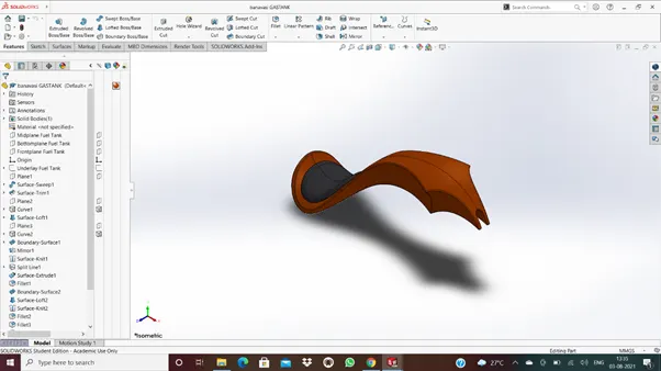
13.GASTANK:
In this part model, the number of tool surfaces are used. They are
Surface trim, surface knit, loft surface, boundary surface, sweep surface, sweep cut, fillets.
MODELLING OF GASTANK:
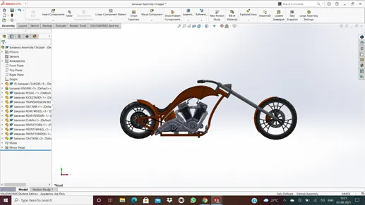
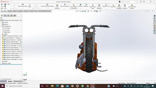
ASSEMBLY OF CHOPPER:
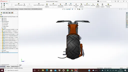
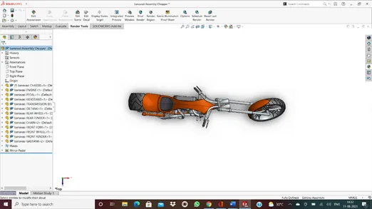
RENDERING:
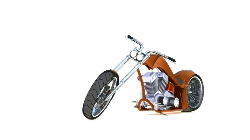
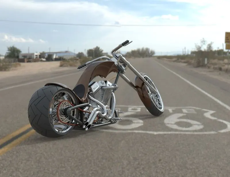
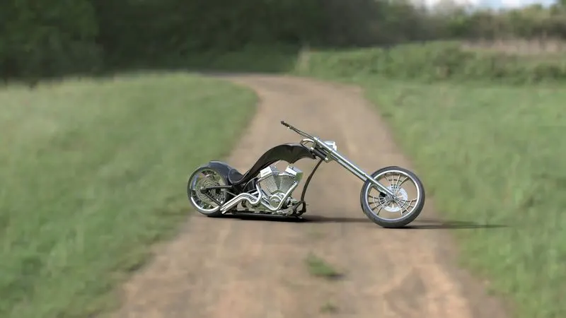
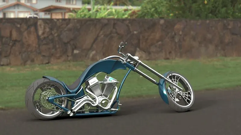
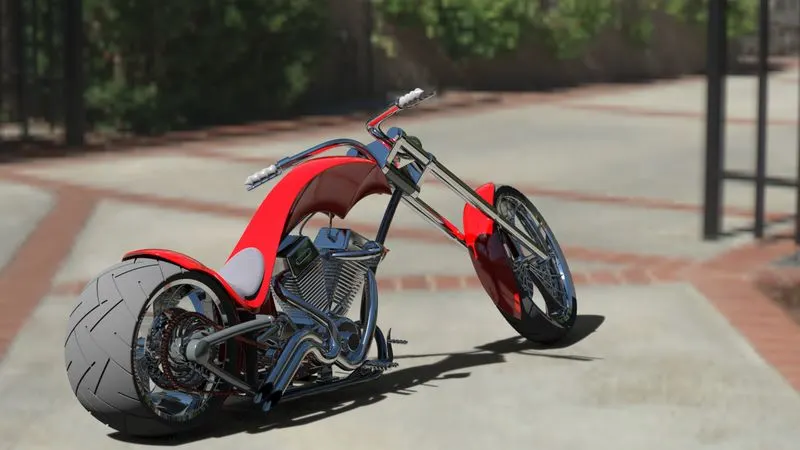
The final step of the bike to make it look realistic as we have already discuss the uses of rendering a model here we try to make it look as realistic as it was possible we started off with checking the appearance added on all the parts then we to make it look more stylish we add some decals on the rear fender and the face of the oil tank, now we try to make it more realistic by giving it a camera view setting the desired lights and the focal distance creating the angle of the view and saving the camera angle which gave a realistic view to the chopper. Now we take our assembly file into solid works visualize where we start making the product more and more realistic with adding the background changing the and adjusting the brightness, shadow density and gamma levels according to the different requirements of the different backgrounds changing the color of the model and checking what suits the best with which background until we get the desired and astonishing product ready.
RENDERING IMAGES:
- ASSEMBLY CHOPPER FINAL RENDERING:
- RT66 CHOPPER RENDERING:
- GERMAN DIRTROAD CHOPPER RENDERING:
- THUNDERROAD CHOPPER RENDERING:
- SUNNY DRIVEAWAY CHOPPER RENDERING:
CONCLUSION:
All the parts of the American chopper are modelled and assembled together successfully using solid works
We have used a lot of HDR environments, appearances, scenes, and finally rendered also.