Week 11 - Final project
DESIGN OF OF DOOR TRIM PANEL
Objectives:
To create an ASSEMBLY of DOOR TRIM PANEL.
To create TOOLING AXIS, CLASS A, CLASS B & CLASS C surface for different parts such as DOOR ARM REST, MAP POCKET, BOTTLE HOLDER & LOWER SUBSTRATE.
To add thickness to different parts such as DOOR ARM REST, MAP POCKET, BOTTLE HOLDER & LOWER SUBSTRATES.
To design FLANGES, DOG HOUSE WITH PUSH PIN & HEAT STAKES of DOOR TRIM PANEL & add thickness to it.
To perform draft analysis on final component of DOOR TRIM PANEL part model.
Glossary:
DOOR TRIM PANEL:- A door trim panel covers the parts inside a car door, like the window regulator, power window motor, and wirings. It also protects these components from damage.
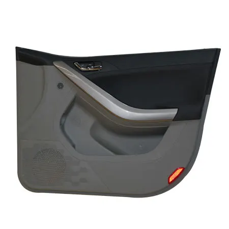
Here it contains 4 parts such as:
- Door arm rest
- Map pocket
- Bottle holder
- Lower substrate
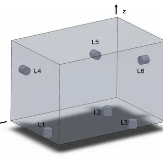
3 - 2 - 1 PRINCIPLE:- This principle is used for locating the job. Every object have 12 degrees of freedom - translational as well as rotational movement along X,Y & Z direction. When part is needed to be machined or welded, operator needs to think about how to stop unnecessary movements of an object and to setup object in required direction of motion.
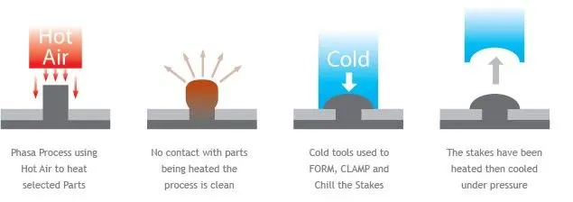
HEAT STAKING:- It is an assembly method which uses controlled melting and reforming of a plastic stud or boss to capture or lock another plastic or metal component of an assembly in place.
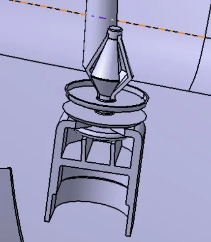
DOG HOUSE WITH PUSH PIN:- These are supporting parts, which are required to fix position of parts in assembly.
FLANGE:- It is used for stabilizing and guiding the movements of a machine or its components.
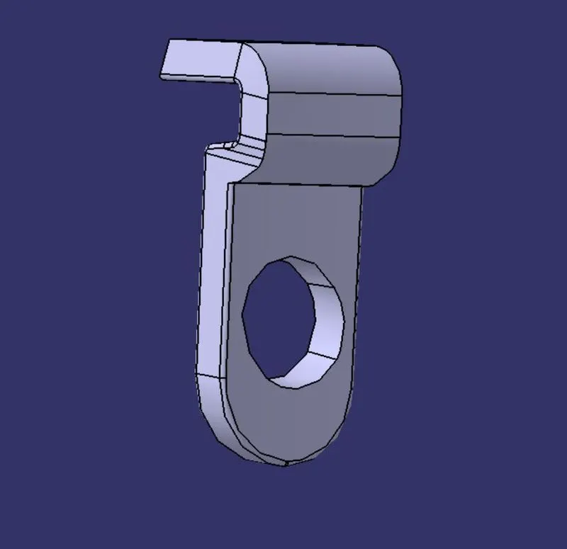
Creation of DOOR ARM REST:
- FUNCTION:- It is used for providing ergonomic relief to occupant for resting his hand as well as facilitating occupant safety during a side impact collision.
- MAIN TOOLING AXIS:-
- Select Class A surface and create a center point on it and place axis system on it.
- Create 2 intersection curves in X and Y direction. With help of these curves, create 2 axis lines.
- Use these lines to create a BISECTING LINE between them. Rename it as MAIN TOOLING AXIS.
- Publish this MAIN TOOLING AXIS using
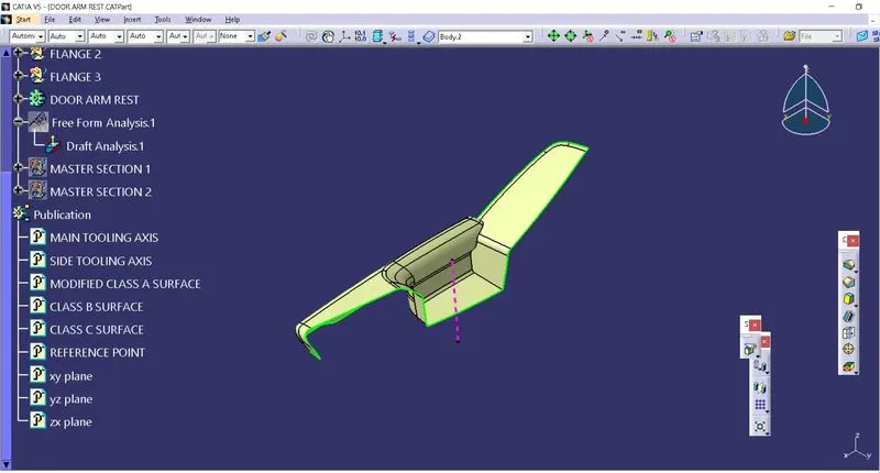
- SIDE TOOLING AXIS:-
- Select Class A surface middle portion where draft analysis is negative and create a center point on it.
- Use this point to create line in Y direction. Rename it as SIDE TOOLING AXIS.
- Publish this SIDE TOOLING AXIS using
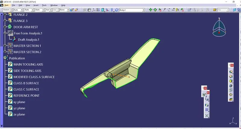
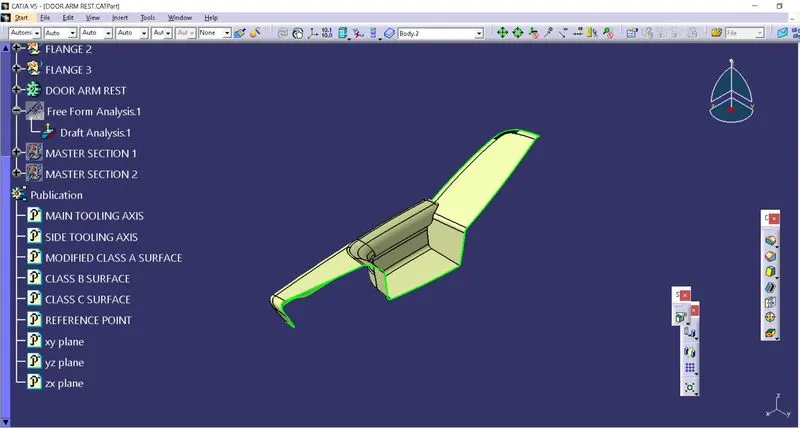
- CLASS A SURFACE:-
- First, create Class A surface using JOIN command to connect different surfaces given in part file. Here merging distance is given 1 mm.
- Here I have used spline to split the surface. Rename it as Class A surface.
- Publish it using PUBLICATION.
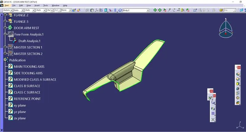
- CLASS B SURFACE:-
- Here Class B surface must be below Class A surface to create solid part of required thickness of 5 mm.
- Use extrapolate, fill, multi-section surface whenever required to create Class B surface.
- Join all surface patches & Rename it as Class B surface.
- Publish this Class B surface using
- CLASS C SURFACE:-
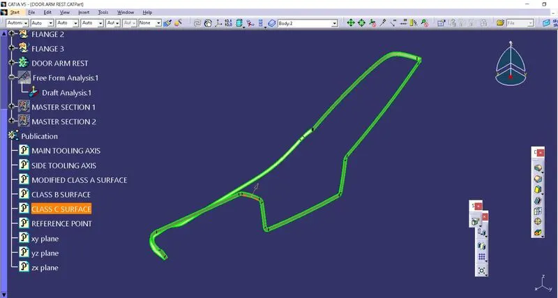
- EXTRACT boundary from Class A surface using MULTIPLE EXTRACT with no propagation.
- Now, use CURVE SMOOTH option to smooth out every curve extracted from Class A surface.
- Apply SWEEP on the CURVE SMOOTH with draft direction
- Here use CURVE SMOOTH as guiding curve and MAIN TOOLING AXIS as draft direction. Apply 3° draft and length should be about 5 mm for FINAL TRIM.
- For corners, EXTRACT boundary separately.
- Use SWEEP with draft direction as given in above steps.
- JOIN surfaces with merging distance of 001 mm except corners.
- Some portions of surfaces are required to use FILL, MULTI-SECTION SURFACE to create Class C surface.
- EXTRAPOLATE surfaces around corners and TRIM them together with this JOIN.
- Rename & Publish this TRIM as Class C surface using
- SOLID PART:-
- Connect Class A and Class C surface using JOIN
- Now, TRIM this with Class B surface.
- Check this FINAL TRIM for gaps using BOUNDARY
- When there is no gaps between surfaces, use CLOSE SURFACE to create a solid body from surface.
- In this way, DOOR ARM REST is created.
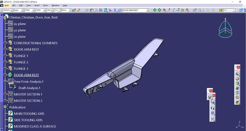
- FLANGES:-
- Use MASTER SECTION to extract lines using PROJECT 3D ELEMENTS and ISOLATE
- Create sketch from these lines and create surface using SWEEP IN DRAFT DIRECTION.
- Offset this surface to create B surface and extrapolate it.
- Now, create C surface in direction of MAIN TOOLING AXIS. Join it with main surface and do final trim with B surface.
- Create FLANGE solid part using close surface option.
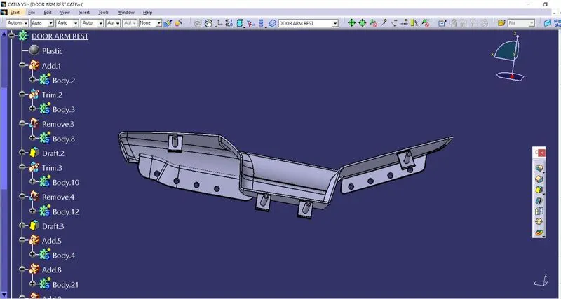
- Create a construction line parallel to MULTIPLE EXTRACT.
- Create 4 points at equidistance on this construction line.
- 5 mm gap required along diameter between heat stake and its hole according to guideline.
- Add CLEARANCE HOLES here for heat stakes about 6 mm diameter on points created and give draft of 0.5° angle with SIDE TOOLING AXIS & fillet required on it.
- Add this with DOOR ARM REST BODY.
- Use same steps to create other flanges on the sides of DOOR ARM REST and at last ADD it with main DOOR ARM REST.
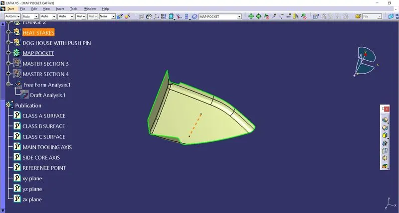
- HEAT STAKES:-
- Extract boundaries from Class A surface using MULTIPLE EXTRACT.
- Now, use PARALLEL CURVE to offset this curve.
- Create points with length or ratio on curve.
- Now, create new sketch on one point with 5 & 7.5 mm diameter concentric circles.
- EXTRUDE this sketch upto Class A surface and give draft of 0.5° angle on it.
- Now, use PASTE SPECIAL to copy-paste this one HEAT STAKE on flange.
- ADD this Heat stake with flange body with DOOR ARM REST
- DRAFT ANALYSIS:-
- Go to insert > analysis > feature draft analysis or directly click on Feature draft analysis icon from menu.
- First select compass option from pop-up menu to set axis system coincide with tooling axis.
- Here change position of MAIN TOOLING AXIS by moving compass location and use lock option to fix it to give every surface a proper draft.
- Surface model will turn into green colour surface, which shows that draft for model is in limit upto 3 degrees. Here I have given green colour for 3 degree draft, light blue for 0 and red colour for negative draft.
- Run quick analysis on model and if any draft angle is more than limit, then one can apply new value of it in pop up box.
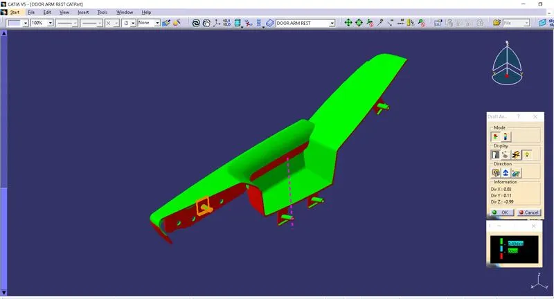
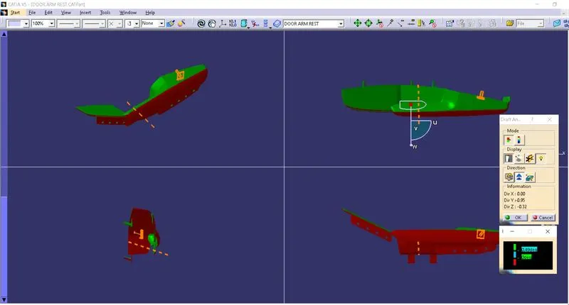
- Full analysis shows different draft angles with different colours as shown in figure.
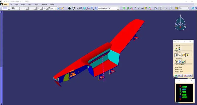
- Here is an example of INVERT DRAFT DIRECTION
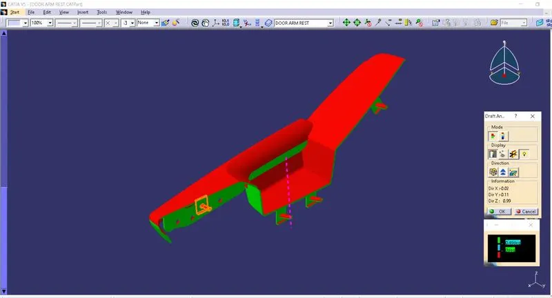
- Below image shows the different views of draft analysis of DOOR ARM REST
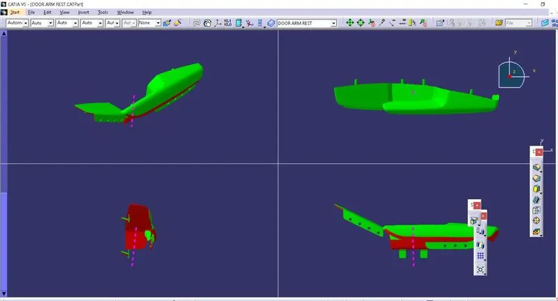
- Also, here are images of draft analysis of 5 degree draft in direction of SIDE TOOLING AXIS.
Creation of MAP POCKET:
- FUNCTION:- It is designed as a lightweight way to retain charts, maps and magazines in Door trim panel.
- MAIN TOOLING AXIS:-
- Select Class A surface and create a center point on it and place axis system on it.
- Create 2 intersection curves in X and Y direction. With help of these curves, create 2 axis lines.
- Use these lines to create a BISECTING LINE between them. Rename it as MAIN TOOLING AXIS.
- Publish this MAIN TOOLING AXIS using
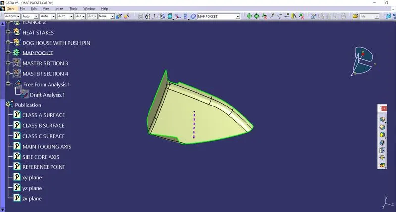
- SIDE TOOLING AXIS:-
- SIDE TOOLING AXIS is required for DOG HOUSE
- Select a center point on Class A surface.
- Use this point to create line in Z direction. Rename it as SIDE TOOLING AXIS.
- Publish this SIDE TOOLING AXIS using
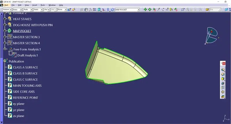
- CLASS A SURFACE:-
- First, create Class A surface using JOIN command to connect different surfaces given in part file. Here merging distance is given 001 mm.
- Rename it as Class A surface. Publish it using PUBLICATION.
- CLASS B SURFACE:-
- Here Class B surface must be below Class A surface to create solid part of required thickness of 5 mm.
- Use extrapolate, fill, multi-section surface whenever required to create Class B surface.
- Join all surface patches & Rename it as Class B surface. Here merging distance is 001 mm.
- Publish this Class B surface using
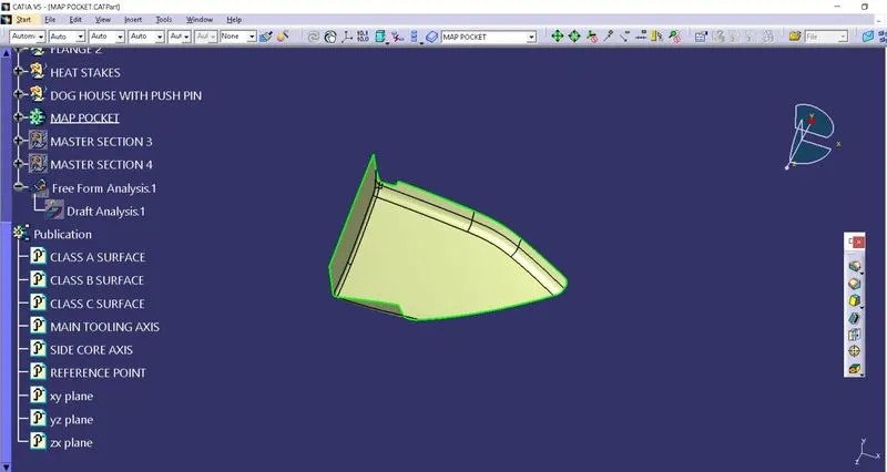
- CLASS C SURFACE:-
- EXTRACT boundary from Class A surface using MULTIPLE EXTRACT with no propagation.
- Now, use CURVE SMOOTH option to smooth out every curve extracted from Class A surface.
- Apply SWEEP on the CURVE SMOOTH with draft direction
- Here use CURVE SMOOTH as guiding curve and MAIN TOOLING AXIS as draft direction. Apply 3° draft and length should be about 5 mm for FINAL TRIM.
- For corners, EXTRACT boundary separately.
- Use SWEEP with draft direction as given in above steps.
- JOIN surfaces with merging distance of 001 mm except corners.
- Some portions of surfaces are required to use FILL, MULTI-SECTION SURFACE to create Class C surface.
- EXTRAPOLATE surfaces around corners and TRIM them together with this JOIN.
- Rename & Publish this TRIM as Class C surface using
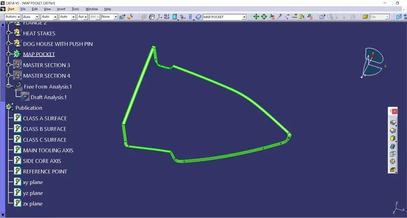
- SOLID PART:-
- Connect Class A and Class C surface using JOIN
- Now, TRIM this with Class B surface.
- Check this FINAL TRIM for gaps using BOUNDARY
- When there is no gaps between surfaces, use CLOSE SURFACE to create a solid body from surface.
- In this way, MAP POCKET is created.
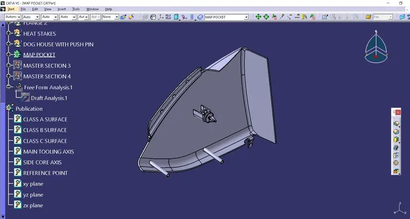
- FLANGES:-
- Use MASTER SECTION to extract lines using PROJECT 3D ELEMENTS and ISOLATE
- Create sketch from these lines and create surface using SWEEP IN DRAFT DIRECTION.
- Offset this surface to create B surface and extrapolate it.
- Now, create C surface in direction of MAIN TOOLING AXIS. Join it with main surface and do final trim with B surface.
- Create FLANGE solid part using close surface option.
- Create a construction line parallel to MULTIPLE EXTRACT.
- Create 3 points at equidistance on this construction line.
- 5 mm gap required along diameter between heat stake and its hole according to guideline.
- Add CLEARANCE HOLES here for heat stakes about 6 mm diameter on points created and give draft of 0.5° angle with SIDE TOOLING AXIS & fillet required on it.
- Add this with MAP POCKET BODY.
- Use same steps to create other flanges on the sides of MAP POCKET and at last ADD it with main MAP POCKET.
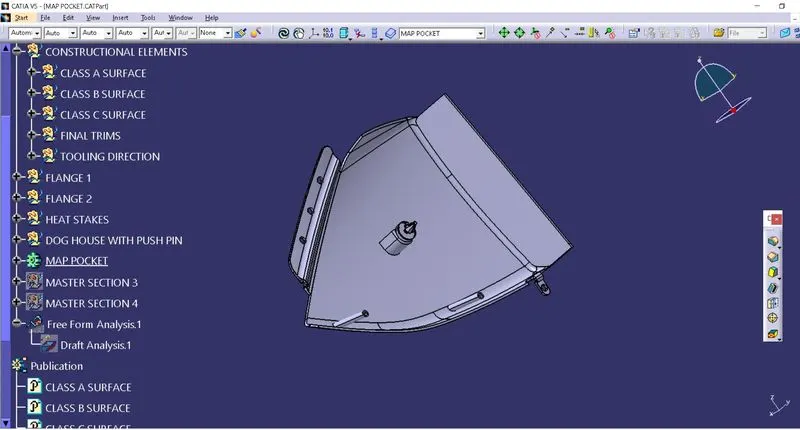
- CREATION OF DOG HOUSE WITH PUSH PIN:-
- First, create sketch of DOG HOUSE at center point according to dimensions.
- Extrude it about 28 mm in one direction and 5 mm in other.
- Extract faces from above extrude and offset this surface inside about 2 mm. Split EXTRUDE body with this offset.
- Now, apply 5° draft inside & outside faces. Apply fillet of 3 mm on the edges of this SPLIT body.
- To avoid sink mark, create surface body as shown in figure. Apply 3 mm fillet on edges.
- Split this extrude with surface body.
- Apply 3 mm on inside edges & 3 mm fillet on split edges.
- Now, create PUSH PIN on top of DOG HOUSE as shown in figure.
- Revolve the sketch of PUSH PIN about center axis.
- Now, make hollow inside of PUSH PIN by creating an inside offset of 1 mm & revolving it.
- After that, 3 slots in PUSH PIN is required. Create an outside offset of 1 mm & revolving it. Apply some required fillet on edges.
- TRANSLATE it on top of DOG HOUSE as shown in figure. ADD this to MAIN POCKET body.
- HEAT STAKES:-
- Extract boundaries from Class A surface using MULTIPLE EXTRACT.
- Now, use PARALLEL CURVE to offset this curve.
- Create points with length or ratio on curve.
- Now, create new sketch on one point with 5 & 7.5 mm diameter concentric circles.
- EXTRUDE this sketch upto Class A surface and give draft of 0.5° angle on it.
- Now, use PASTE SPECIAL to copy-paste this one HEAT STAKE on edges of LOWER SUBSTRATE.
- ADD this Heat stake with MAP POCKET
- DRAFT ANALYSIS:-
- Go to insert > analysis > feature draft analysis or directly click on Feature draft analysis icon from menu.
- First select compass option from pop-up menu to set axis system coincide with tooling axis.
- Here change position of MAIN TOOLING AXIS by moving compass location and use lock option to fix it to give every surface a proper draft.
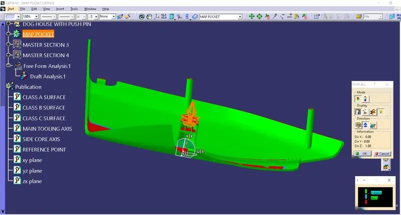
- Surface model will turn into green colour surface, which shows that draft for model is in limit upto 3 degrees. Here I have given green colour for 3 degree draft, light blue for 0 and red colour for negative draft.
- Run quick analysis on model and if any draft angle is more than limit, then one can apply new value of it in pop up box.
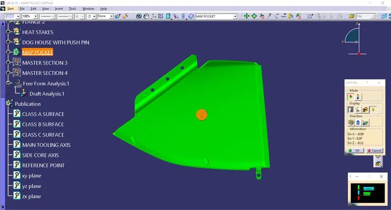
- Full analysis shows different draft angles with different colours as shown in figure.
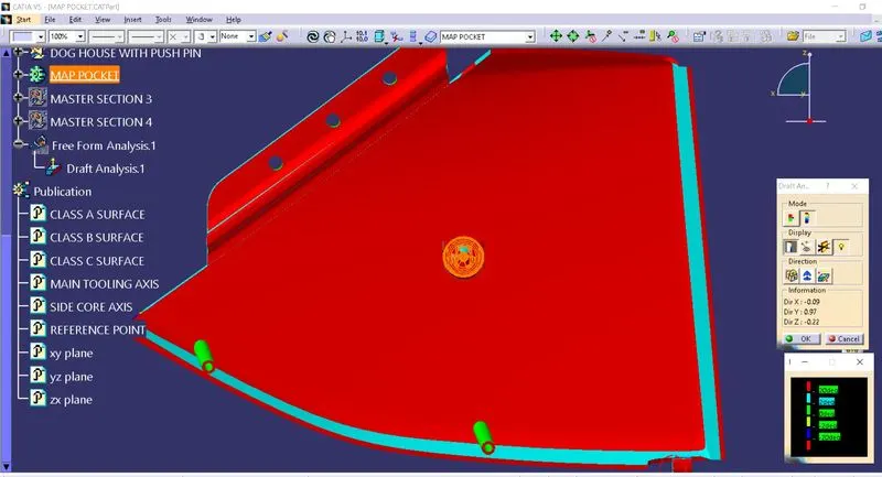
- Here is an example of INVERT DRAFT DIRECTION
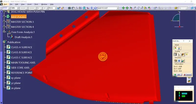
- Below image shows the different views of draft analysis of MAP POCKET
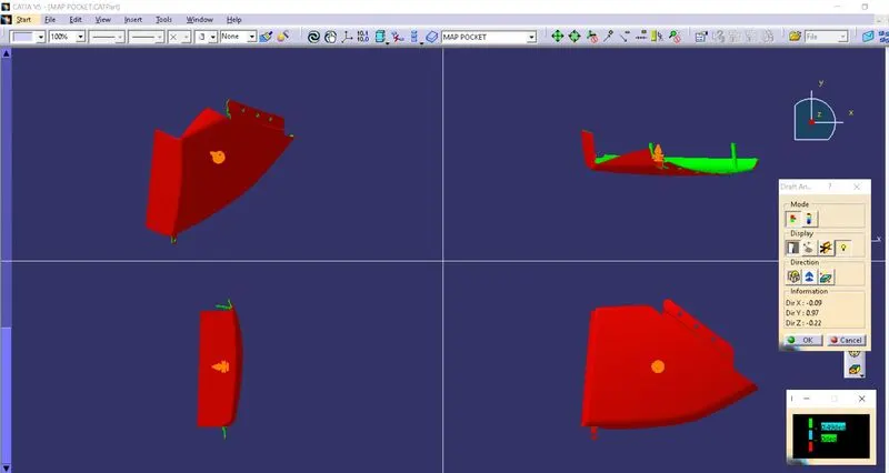
- Also, here are images of draft analysis of 5 degree draft in direction of SIDE TOOLING AXIS.
Creation of BOTTLE HOLDER:
- FUNCTION:- It is used for holding a cup or other drinking vessel.
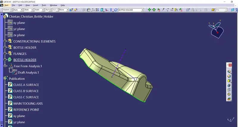
- MAIN TOOLING AXIS:-
- Select Class A surface and create a center point on it and place axis system on it.
- Create 2 intersection curves in X and Y direction. With help of these curves, create 2 axis lines.
- Use these lines to create a BISECTING LINE between them. Rename it as MAIN TOOLING AXIS.
- Publish this MAIN TOOLING AXIS using
- CLASS A SURFACE:-
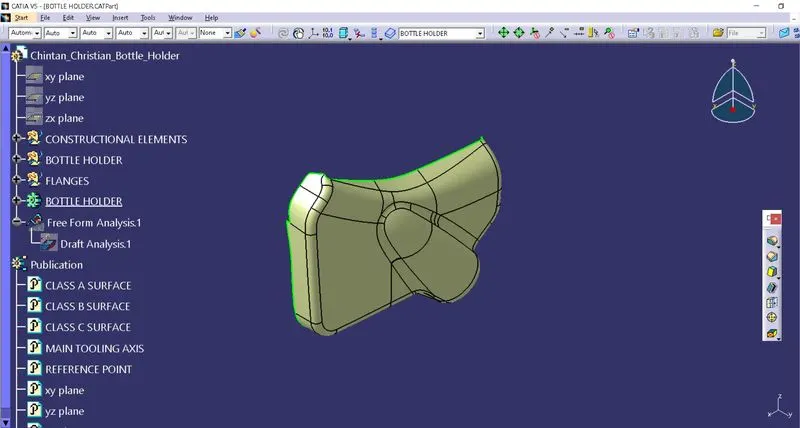
- First, create Class A surface using JOIN command to connect different surfaces given in part file. Here merging distance is given 1 mm.
- Rename it as Class A surface & Publish it using PUBLICATION.
- CLASS B SURFACE:-
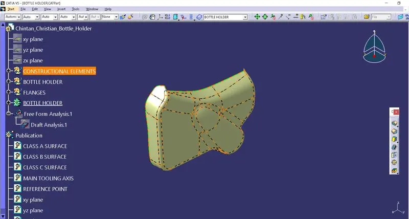
- Here Class B surface must be below Class A surface to create solid part of required thickness of 5 mm.
- Use extrapolate, fill, multi-section surface whenever required to create Class B surface.
- Join all surface patches & Rename it as Class B surface. Here merging distance is 001 mm.
- Publish this Class B surface using
- CLASS C SURFACE:-
- EXTRACT boundary from Class A surface using MULTIPLE EXTRACT with no propagation.
- Now, use CURVE SMOOTH option to smooth out every curve extracted from Class A surface.
- Apply SWEEP on the CURVE SMOOTH with draft direction
- Here use CURVE SMOOTH as guiding curve and MAIN TOOLING AXIS as draft direction. Apply 3° draft and length should be about 5 mm for FINAL TRIM.
- For corners, EXTRACT boundary separately.
- Use SWEEP with draft direction as given in above steps.
- JOIN surfaces with merging distance of 001 mm except corners.
- Some portions of surfaces are required to use FILL, MULTI-SECTION SURFACE to create Class C surface.
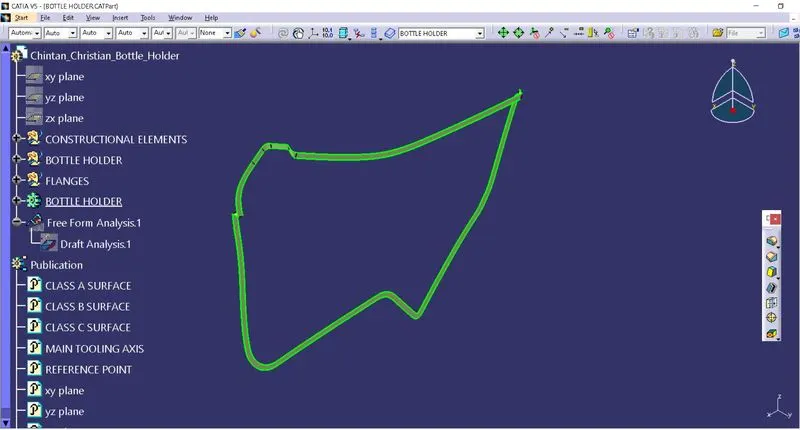
- EXTRAPOLATE surfaces around corners and TRIM them together with this JOIN. Here merging distance is 001 mm.
- Rename & Publish this TRIM as Class C surface using
- SOLID PART:-
- Connect Class A and Class C surface using JOIN
- Now, TRIM this with Class B surface.
- Check this FINAL TRIM for gaps using BOUNDARY
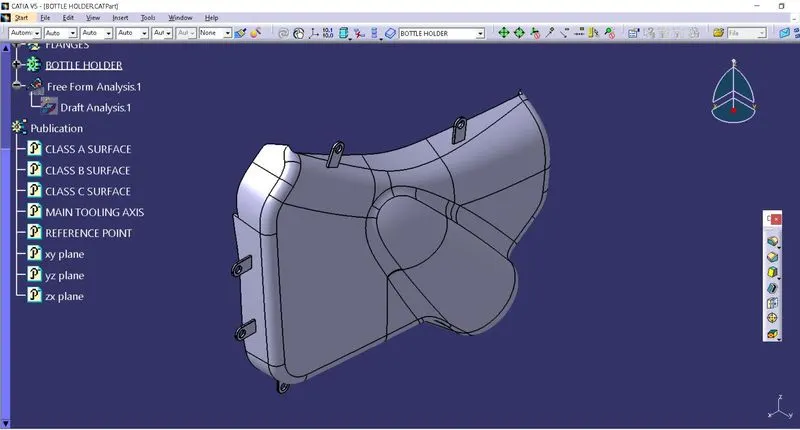
- When there is no gaps between surfaces, use CLOSE SURFACE to create a solid body from surface.
- In this way, BOTTLE HOLDER is created.
- FLANGES:-
- Use MASTER SECTION to extract lines using PROJECT 3D ELEMENTS and ISOLATE
- Create sketch from these lines and create surface using SWEEP IN DRAFT DIRECTION.
- Offset this surface to create B surface and extrapolate it.
- Now, create C surface in direction of MAIN TOOLING AXIS. Join it with main surface and do final trim with B surface.
- Create FLANGE solid part using close surface option.
- Create a construction line parallel to MULTIPLE EXTRACT.
- Create 5 points around border of BOTTLE HOLDER.
- 5 mm gap required along diameter between heat stake and its hole according to guideline.
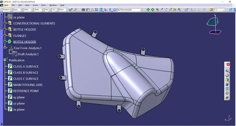
- Add CLEARANCE HOLES here for heat stakes about 6 mm diameter on points created and give draft of 0.5° angle with SIDE TOOLING AXIS & fillet required on it.
- COPY-PASTE this flange using result with link TRANSLATE and ROTATE it on given points.
- Add these flanges with BOTTLE HOLDER
- DRAFT ANALYSIS:-
- Go to insert > analysis > feature draft analysis or directly click on Feature draft analysis icon from menu.
- First select compass option from pop-up menu to set axis system coincide with tooling axis.
- Here change position of MAIN TOOLING AXIS by moving compass location and use lock option to fix it to give every surface a proper draft.
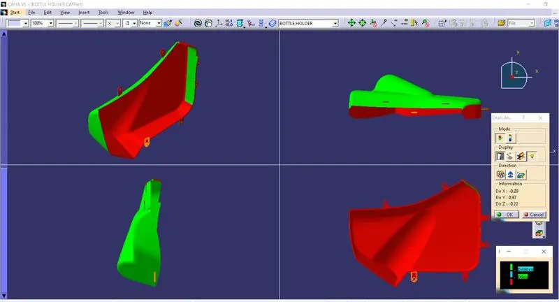
- Surface model will turn into green colour surface, which shows that draft for model is in limit upto 3 degrees. Here I have given green colour for 3 degree draft, light blue for 0 and red colour for negative draft.
- Run quick analysis on model and if any draft angle is more than limit, then one can apply new value of it in pop up box.
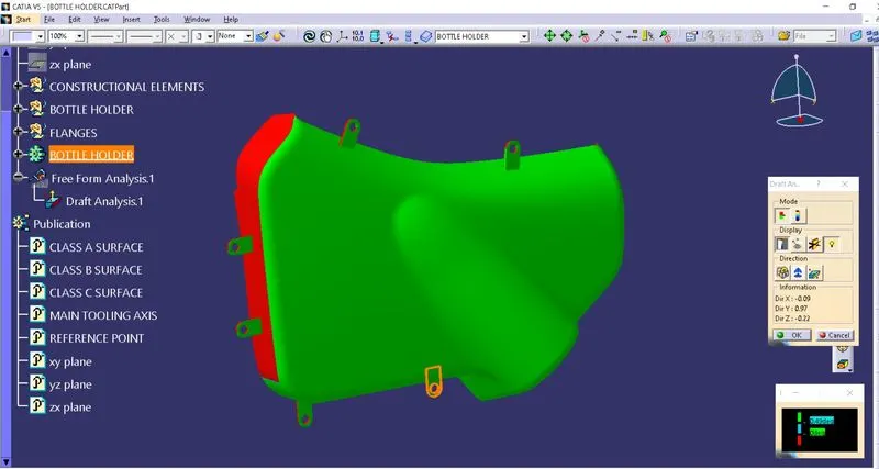
- Full analysis shows different draft angles with different colours as shown in figure.
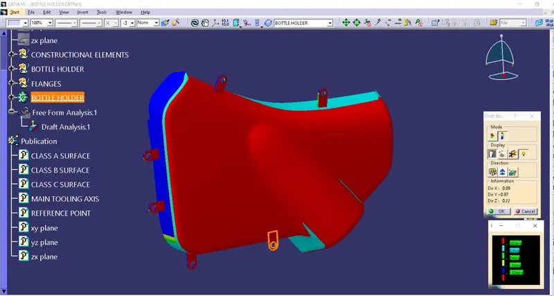
- Here is an example of INVERT DRAFT DIRECTION
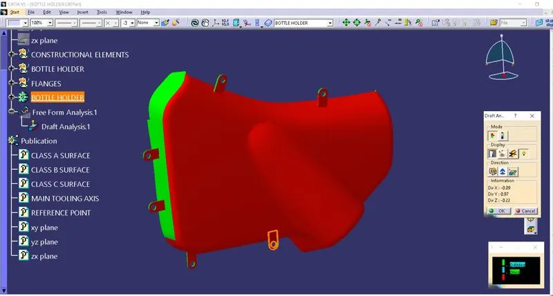
- Below image shows the different views of draft analysis of BOTTLE HOLDER
Creation of LOWER SUBSTRATE:
- FUNCTION:- It is used as supporting structure.
- MAIN TOOLING AXIS:-
- Select Class A surface and create a center point on it and place axis system on it.
- Create 2 intersection curves in X and Y direction. With help of these curves, create 2 axis lines.
- Use these lines to create a BISECTING LINE between them. Rename it as MAIN TOOLING AXIS.
- Publish this MAIN TOOLING AXIS using
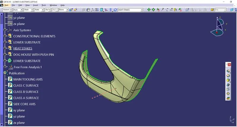
- SIDE TOOLING AXIS:-
- Select a center point on Class A surface.
- Use this point to create line in Z direction. Rename it as SIDE TOOLING AXIS.
- Publish this SIDE TOOLING AXIS using
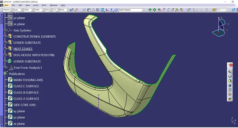
- CLASS A SURFACE:-
- First, create Class A surface using JOIN command to connect different surfaces given in part file. Here merging distance is given 1 mm.
- Here I have used spline to split the surface. Rename it as Class A surface.
- Publish it using PUBLICATION.
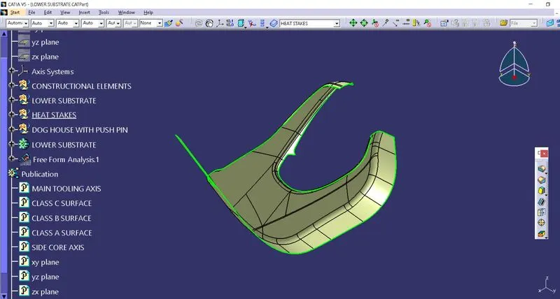
- CLASS B SURFACE:-
- Here Class B surface must be below Class A surface to create solid part of required thickness of 5 mm.
- Use extrapolate, fill, multi-section surface whenever required to create Class B surface.
- Join all surface patches & Rename it as Class B surface. Here merging distance is 1 mm.
- Publish this Class B surface using
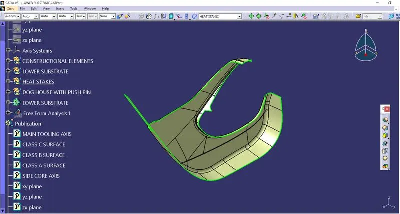
- CLASS C SURFACE:-
- EXTRACT boundary from Class A surface using MULTIPLE EXTRACT with no propagation.
- Now, use CURVE SMOOTH option to smooth out every curve extracted from Class A surface.
- Apply SWEEP on the CURVE SMOOTH with draft direction
- Here use CURVE SMOOTH as guiding curve and MAIN TOOLING AXIS as draft direction. Apply 3° draft and length should be about 5 mm for FINAL TRIM.
- For corners, EXTRACT boundary separately.
- Use SWEEP with draft direction as given in above steps.
- JOIN surfaces with merging distance of 001 mm except corners.
- Some portions of surfaces are required to use FILL, MULTI-SECTION SURFACE to create Class C surface.
- EXTRAPOLATE surfaces around corners and TRIM them together with this JOIN.
- Rename & Publish this TRIM as Class C surface using
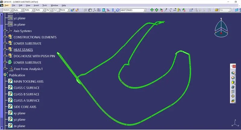
- SOLID PART:-
- Connect Class A and Class C surface using JOIN
- Now, TRIM this with Class B surface.
- Check this FINAL TRIM for gaps using BOUNDARY
- When there is no gaps between surfaces, use CLOSE SURFACE to create a solid body from surface.
- In this way, LOWER SUBSTRATE is created.
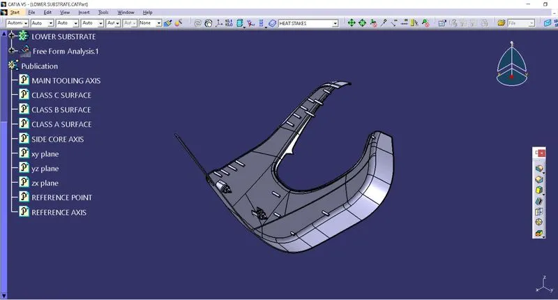
- HEAT STAKES:-
- Extract boundaries from Class A surface using MULTIPLE EXTRACT.
- Now, use PARALLEL CURVE to offset this curve.
- Create points with length or ratio on curve.
- Now, create new sketch on one point with 5 & 7.5 mm diameter concentric circles.
- EXTRUDE this sketch upto Class A surface and give draft of 0.5° angle on it.
- Now, use PASTE SPECIAL to copy-paste this one HEAT STAKE on edges of LOWER SUBSTRATE.
- ADD these Heat stakes with MAP POCKET
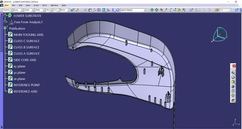
- CREATION OF DOG HOUSE WITH PUSH PIN:-
- First, create sketch of DOG HOUSE at center point according to dimensions.
- Extrude it about 28 mm in one direction and 5 mm in other.
- Extract faces from above extrude and offset this surface inside about 2 mm. Split EXTRUDE body with this offset.
- Now, apply 5° draft inside & outside faces. Apply fillet of 3 mm on the edges of this SPLIT body.
- To avoid sink mark, create surface body as shown in figure. Apply 3 mm fillet on edges.
- Split this extrude with surface body.
- Apply 3 mm on inside edges & 3 mm fillet on split edges.
- Now, create PUSH PIN on top of DOG HOUSE as shown in figure.
- Revolve the sketch of PUSH PIN about center axis.
- Now, make hollow inside of PUSH PIN by creating an inside offset of 1 mm & revolving it.
- After that, 3 slots in PUSH PIN is required. Create an outside offset of 1 mm & revolving it. Apply some required fillet on edges.
- TRANSLATE it on top of DOG HOUSE as shown in figure. ADD this to MAIN POCKET body.
- DRAFT ANALYSIS:-
- Go to insert > analysis > feature draft analysis or directly click on Feature draft analysis icon from menu.
- First select compass option from pop-up menu to set axis system coincide with tooling axis.
- Here change position of MAIN TOOLING AXIS by moving compass location and use lock option to fix it to give every surface a proper draft.
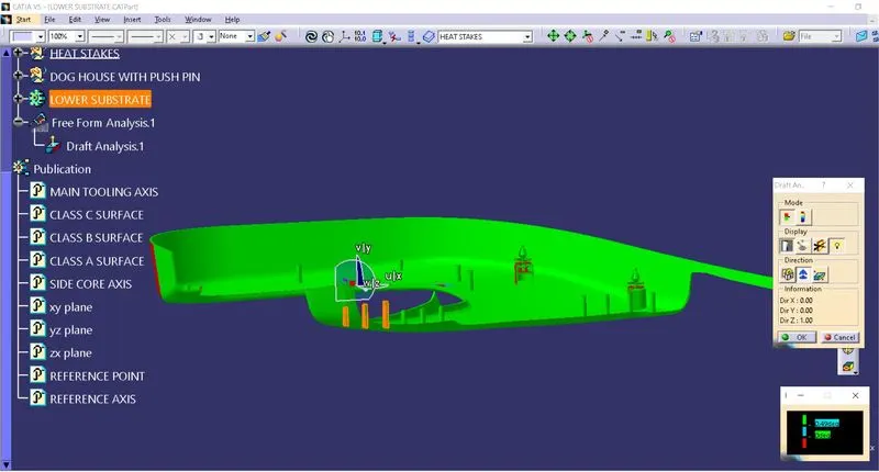
- Surface model will turn into green colour surface, which shows that draft for model is in limit upto 3 degrees. Here I have given green colour for 3 degree draft, light blue for 0 and red colour for negative draft.
- Run quick analysis on model and if any draft angle is more than limit, then one can apply new value of it in pop up box.
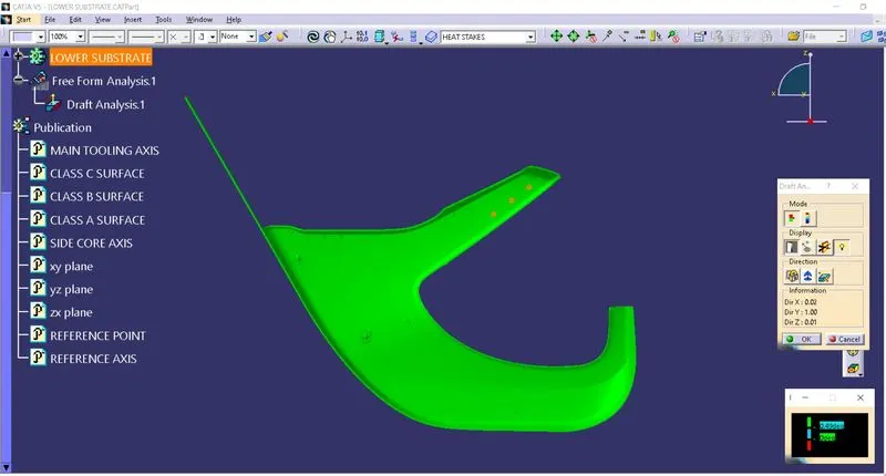
- Full analysis shows different draft angles with different colours as shown in figure.
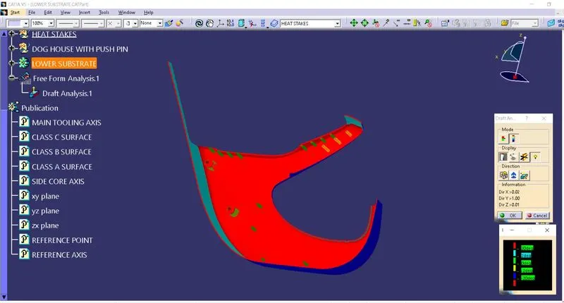
- Here is an example of INVERT DRAFT DIRECTION
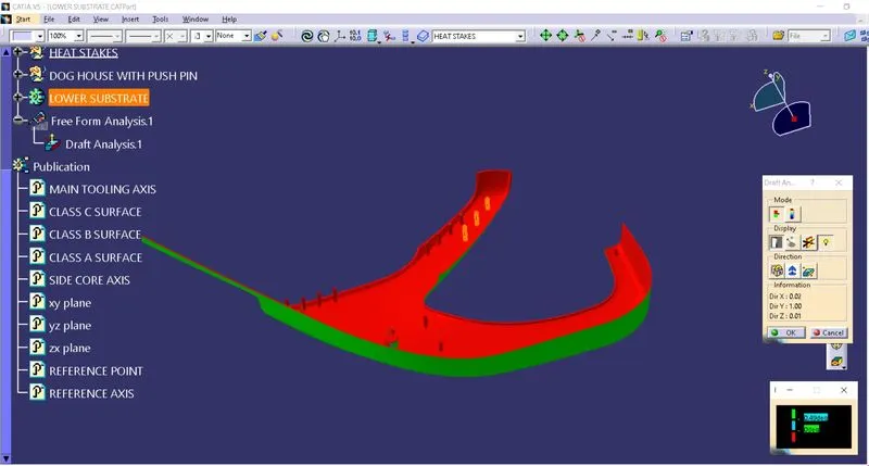
- Below image shows the different views of draft analysis of LOWER SUBSTRATE
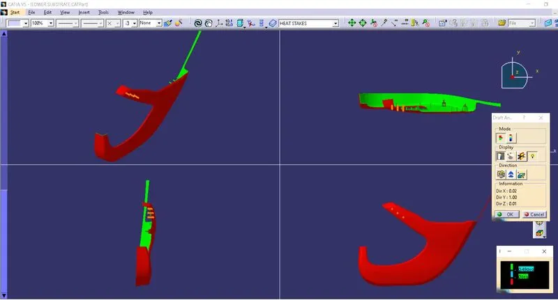
- Also, here are images of draft analysis of 5 degree draft in direction of SIDE TOOLING AXIS.
CREATING ASSEMBLY OF DOOR TRIM PANEL:
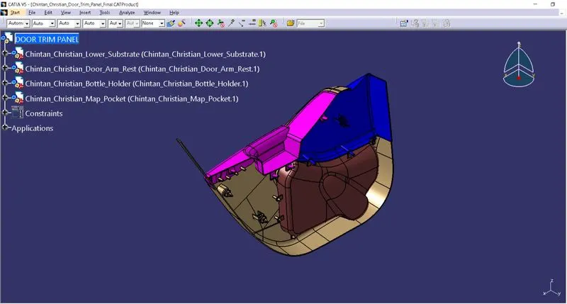
- First add LOWER SUBSTRATE in DOOR TRIM PANEL ASSEMBLY. Add Reference point & publish it with all 3 planes.
- Insert parts by using either COPY-PASTE or using NEW PART / EXISTING PART.
- Change relative positions of all parts using MANIPULATION
- Fix position of LOWER SUBSTRATE using FIX POSITION
- Coincide 2 PLANES of DOOR ARM REST with LOWER SUBSTRATE as shown in figure.
- Insert MAP POCKET. Coincide 2 PLANES with LOWER SUBSTRATE as shown in figure.
- Insert BOTTLE HOLDER. Coincide 2 PLANES with LOWER SUBSTRATE as shown in figure.
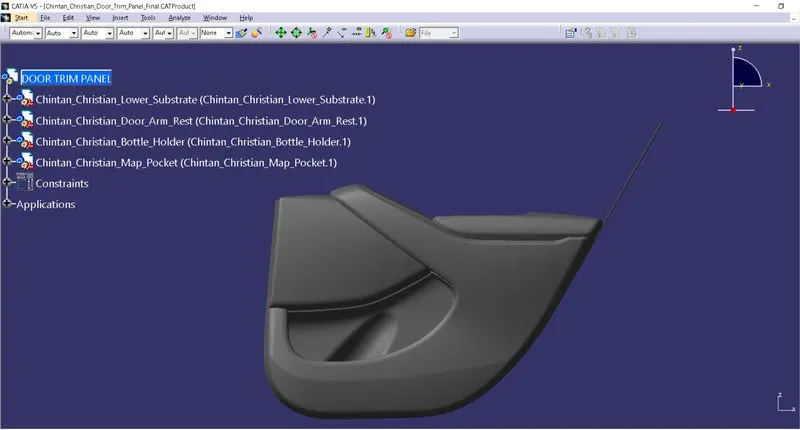
- In this way, ASSEMBLY of DOOR TRIM PANEL is completed.
Conclusion:
I have learned about creation of DOOR ARM REST, MAP POCKET, BOTTLE HOLDER & LOWER SUBSTRATE for DOOR TRIM PANEL as well as ASSEMBLY of it in this challenge.
Also, I understand the importance of FLANGES, HEAT STAKES & DOG HOUSE WITH PUSH PIN design in terms of industry guidelines.