Week 11 - Final project
DOORTRIM FINAL PROJECT
ARM REST
In the final project the input they gave the class A suface and master section for the flanges
in this project they gave four bodies of the door trim of the project.They are
- ARM REST
- LOWER SUBSTRATE
- MAP POCKET
- BOTTLE HOLDER
In this project we have to create the class B, CLASS C AND B side features
first we should measure the the thickness of the component of part and then follow the the master section for the flanges
the over all component thickness is 2.5 mm of the component
and the draft angle is 0.5-3 degree
Then create the B SIDE features we should follow standard and ruler for heat strake, locator and dog house
Method
tooling direction is the direction in which mould or cavity opens .this isthe place where mould splits into two half and class b and c can be formed .also this is the place where class b is taken and what ever necessary correction are required can be done
ARM REST CLASS A
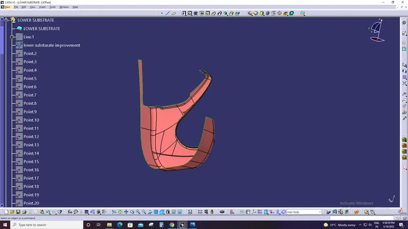
LOWER SUBSTRATE CLASS A
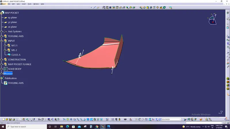
MAP POCKET CLASS A
BOTTLE HOLDER CLASS A
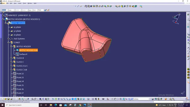
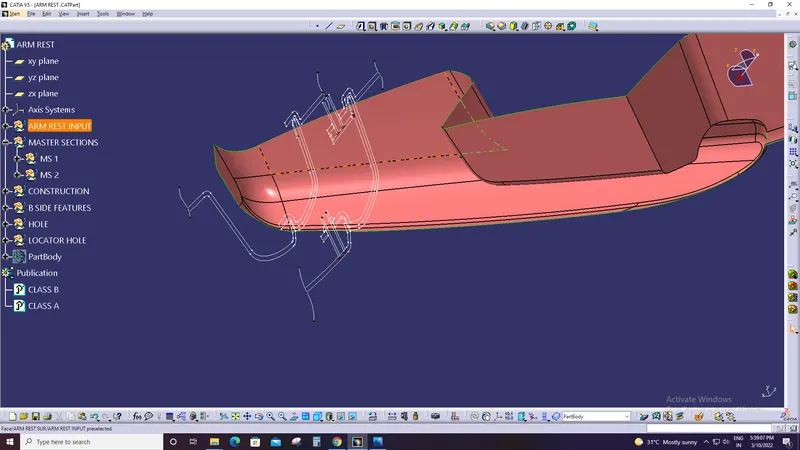
The figure show the class a surface and the master section for the flange. it is the input of the arm rest
and also check the boundary of the class a surface
after check the boundary mesure the thickness of the component of the part with the referance of the of the master section with
the measurung tool the component thickness is 2.5 mm
the over all component thickness is 2.5 in door trim
The next method we have to create the class b surface of arm rest with the help of offset tool
to 2.5mm is shoe in the figure in step 2
After we creating the class b surface is over then we start create the class c suface with the referance of class a surface
After creating the class c surface we have to unhide class and class b suface to extrapolate the class a and class c
and the trim the extra surface
After trim the extra surface of class a and class 2 the component is join together in single part
and then we join in the class b surface in the class a &c
now the all the component is join as the single part inthe plastic component
CLASS A AND CLASS B
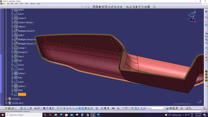
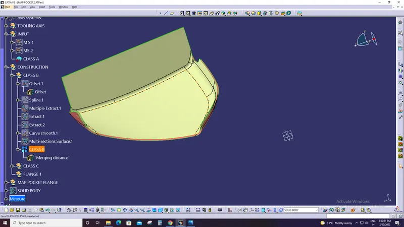
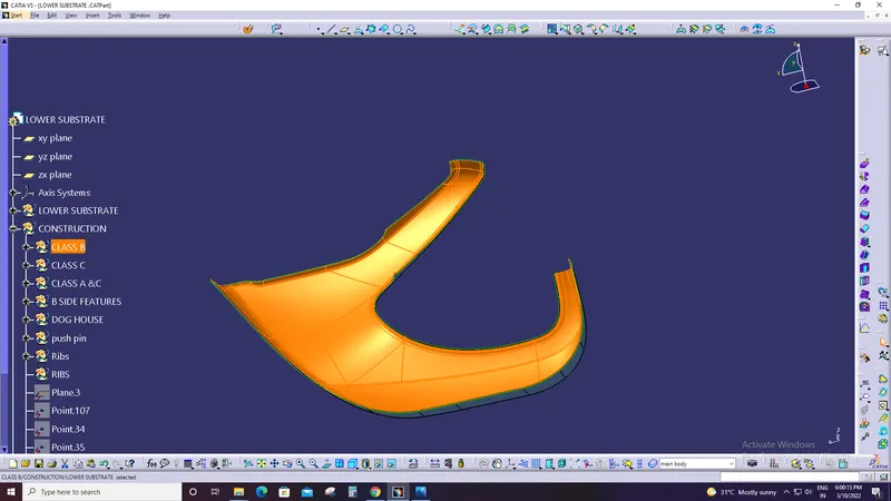
the next step is create the class b surface under the tools of offset
and offset in to 2.5 mm according to master section
and work on patches if anyare accquired .and then fillet were applied after necesary calculation
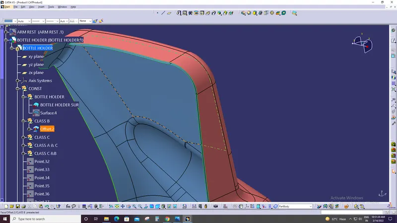
The Class B finish is a quality finish with only minimal imperfections. A Class B finish is the most common finish for exterior surfaces.
It is normally specified on surfaces such as external covers, panels, and parts that are fairly prominen.
CLASS C
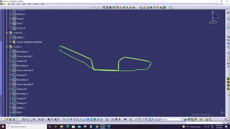
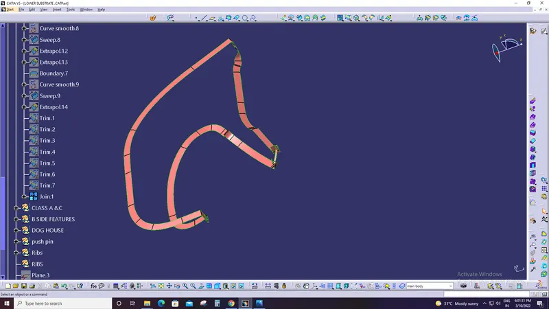
The first step to create boundary in the outer surface in in class a surface
And create the class c with the help of sweep tool and then adjust the angle of the sweep to inclined the sweep
After that to trim the extra surface of the class c surface and show in the figure
AMR REST
LOWER SUBSTRATE
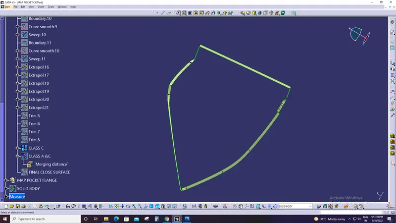
MAP POCKET
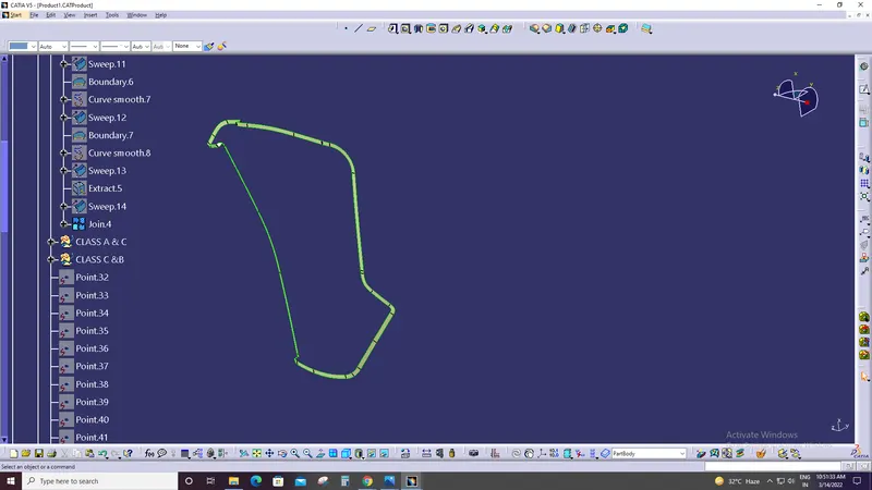
BOTTLE HOLDER
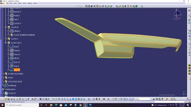
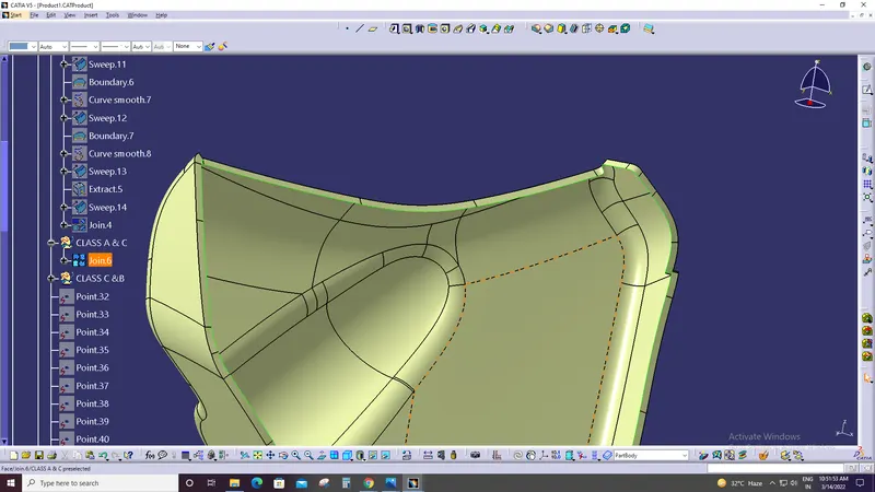
CLASS A & C
In this step we are going to join the class a and class c surface to join .
to joint the class a and c before the we have to extrpolate the all side of class a & c and then use the trim tool and join together the figure show in top
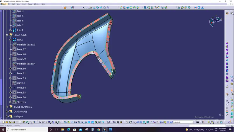
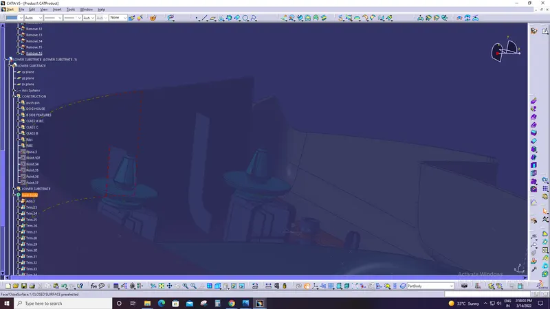
The lower substarte is the second part in door trim project .In this we have the b side feature like locator heat stakes and dog house
the figure is show is lower substarte class a surface now we create the two surface of the lower substarte .And also we create the b side feature nof the lower substrate
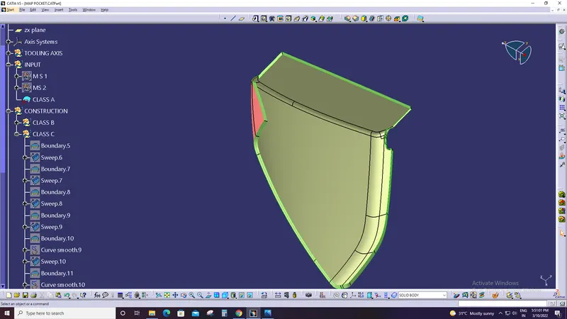
CLASS A,B,&C
The class a and c is joint is together and now we are goint to joint class b surface also and then the full part is complete with plastic component
extrapolate the class b till the surface joint in the class c surface and then trim the surafce. finally the full plastic component
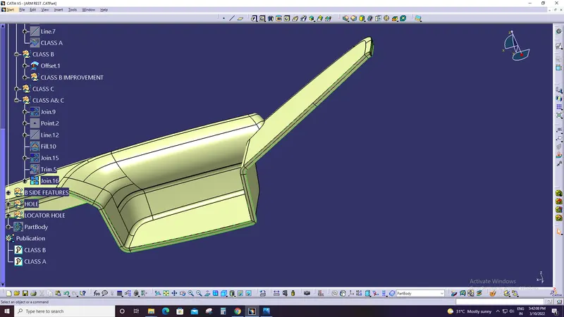
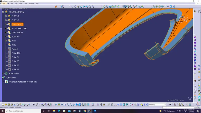
now we are going to convert the plastic componenet into solid component.
insert the body and defined the boady and convert the generative shape design bench into part work bench
After make all component in solid then check the draft ananlysis for the component is show in the figure
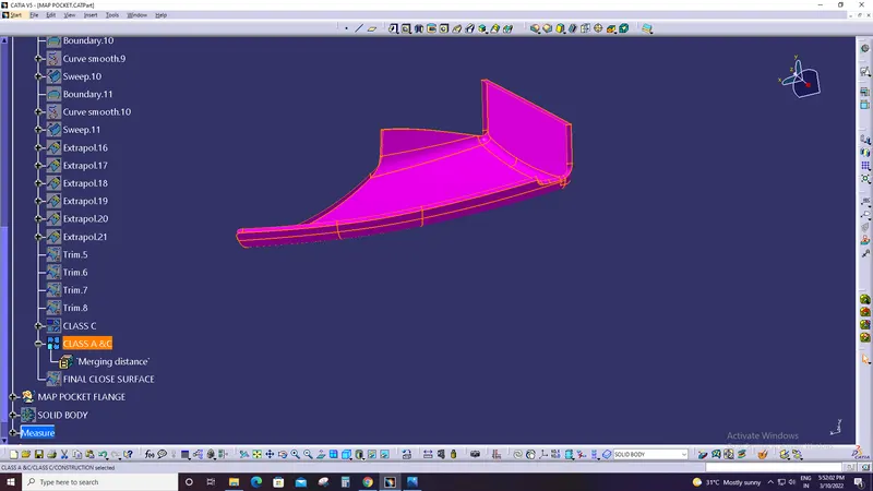
FLANGES
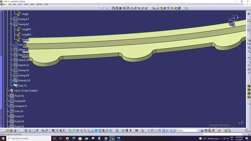
Draw the flange with the referance of master section and make a part of the pad
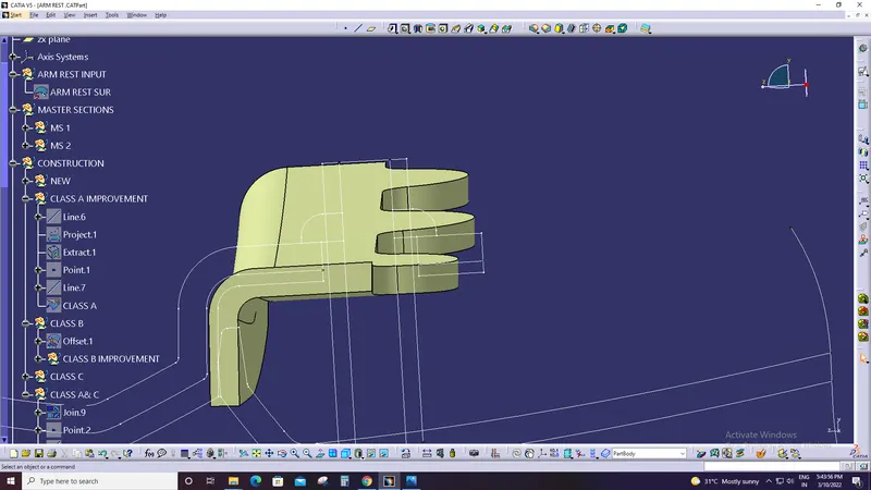
first create the extract the master section of line and extrapolate the line and trim the profile line
and create the guide line with help of boundary and then create guide line
after create the profile and guide line and make the sweep on the profile and take the off set of the sweep the off set is 2.5 mm
and create the sketch for the close surface in the flange and the line is extruded and trim
The flange is complete now we going to convert the plastic component into solid component
with the use of part work bench and close surface tool is use and add the body into part body using boolean operation
Create the two more flange in component as per the same method
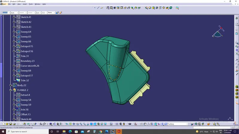
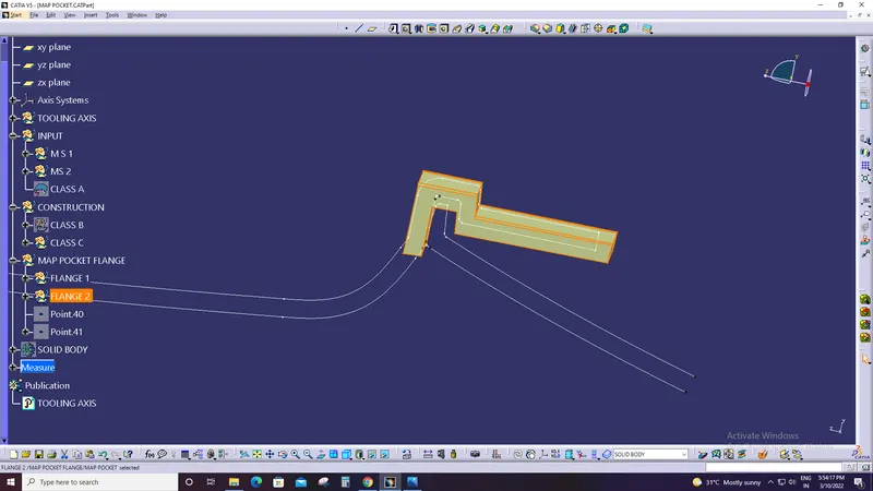
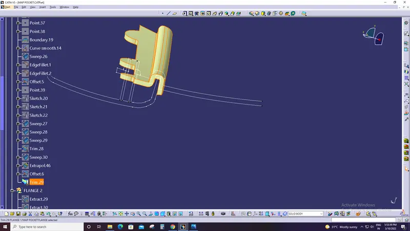
and flanges is over then is covert into close sueface and go to part work bench and use the surface based features and select the closed surafe and also make the body into solid with the help of closed surface tool
After the here also we use the boolean operation final to joint the flange to the main part
HOLE
create the sketch and draw the circle for the clearance hole and and pad the hole after that draft the 0.5 degree draft in the hole and then the remove the hole in part body.
Now we are the going to use the copy the hole and paste on the product and the parasolid ic formed and the translate the hole in required point.
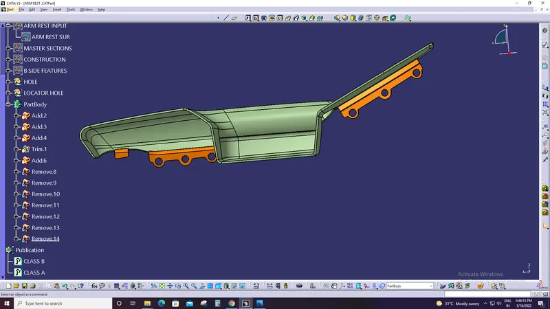
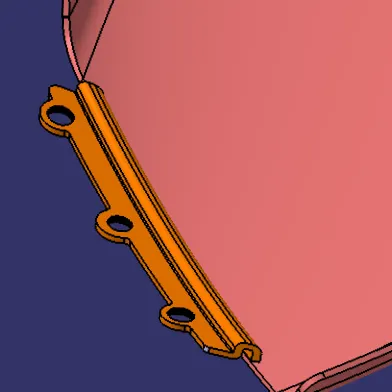
the procedure of the hole is describe in the method of boolena in part work bench. first draw the sketch and pad the sketch in the separate body and the pad the sketch and the is made in the solid .
and the pad is remove in the required palce to remove the from main part body After that defined the main body and use the boolean operation
and remove the hole the and the hole is created on the required palce also the figure is showes in the top
HEAT STAKE
Heat staking also known as thermoplastic staking is the process of joining two dissimilar materials together.
In heat staking we use local heating and cooling to raise the temperature of plastic components and allow plastic reforming to be carried out.
This reforming can be used in a wide variety of applications.
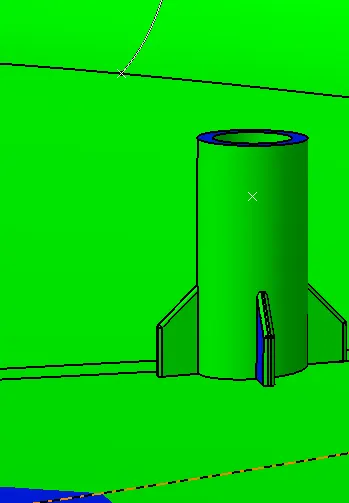
Advantages
- Because the sector being re-formed has reached moulding temperature the completed assembly will be free of stress and strain with no residual memory to promote creep and loosening of parts at a later date.
- Because 80% of the working stake has been reformed and there has been no degrading of material the formed strength will be proportionally equal to that of the base moulding.
- The tools are cool or cold so there is no sticking or material transfer.
- The stakes will shrink as they cool so the final assembly will tighten even further after processing.
- Because the hot air may exceed the melt point of the plastic because of its low thermal capacity and conduction the excess energy will not cause any degradation of the resin; however it may sometimes create slight discoloration of fillers (more visible in light colours).
- It is best to use compatible materials where the melt temperature of the stake is equal to or less than that of the material it passes through. Observe extreme caution where the material from which the stake is moulded is of a much higher melt index than the material being assembled to it or where a thin thermoplastic washer is being fitted
DRAFT ANALYSIS:
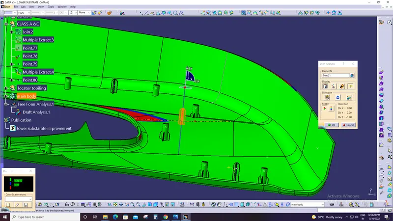
The draft analysis command enables you to detect if the part you drafted will be easily removed. This type of analysis is performed
based on color ranges identifying zones on the analyzed element where the deviation from the draft direction at any point,
corresponds to specified values.
You can modify them by clicking on their corresponding arrow or by entering a value directly in the field.
The mapping texture accuracy depends of the video card used. Therefore, colors displayed on surfaces could be wrong
according to the color scale, when the value displayed on the fly is right because the analysis is recomputed at the cursor
location.
Sometimes, in the case of extremely closed values, it is recommended to switch to the quick mode to improve the color display
accuracy.
The maximal draft analysis accuracy is 0.5 deg.
According to the graphic card performance, this accuracy can be debased.
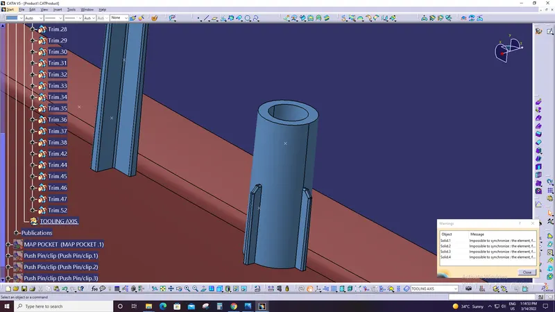
This is the 2d diagram of heat stake in the position sketch and pad the sketch in to the required dimension of the part
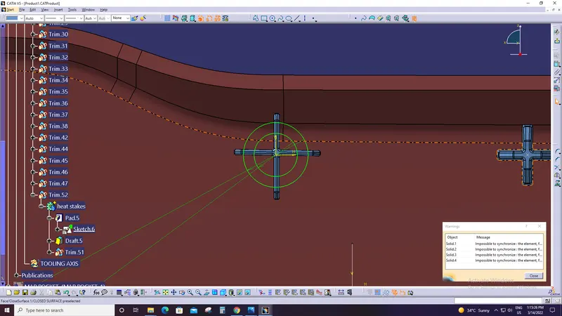
after pad the haet stake then use the draft tool in part word and use the draft ti to draft the heat stake up to 0.5 degree in all side
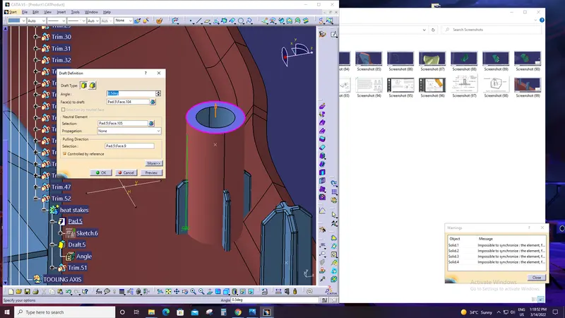
after heat stake is completed.And make the multiple heat stake on the lower substrate with the help of paste special command
and create the cooridnate point where the heat stake is needed and crete multiple point on the lower substrate
after that copy body and paste special on the nain body and then u traslate the para solid and placed on the point
RIBS
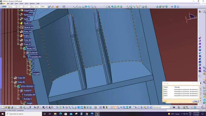
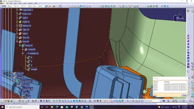
The ribs are supporting structures which gives strength to the thin surface.
It should be connected to other structural features.The
draft angle for the rib is 0.5 deg, fillet radius is 0.25-1 mm.
The design guideline for the rib creation
DOG HOUSE
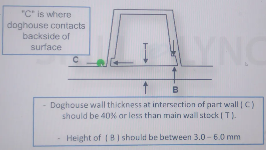
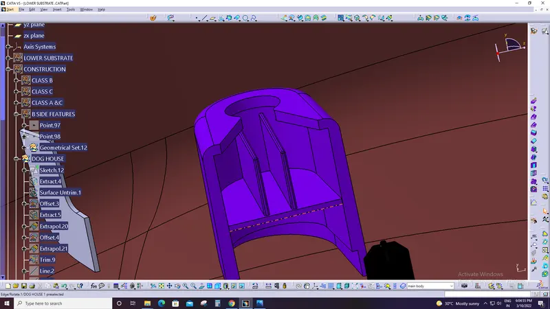
The dog house is the structure to have the screw boss/push clips on it.The dog house is used for the screw boss where we needed
increased height.
Dog house is an engineering feature used in plastic trim design. Dog houses are used as supporting feature.
Sometimes other engineering features like snaps; locators etc. are mounded on them to increase their strength.
The c surface of the dog house should be 40% of wall thickness.
The structure is attached to the component.The dog
house is used to avoid sink marks.
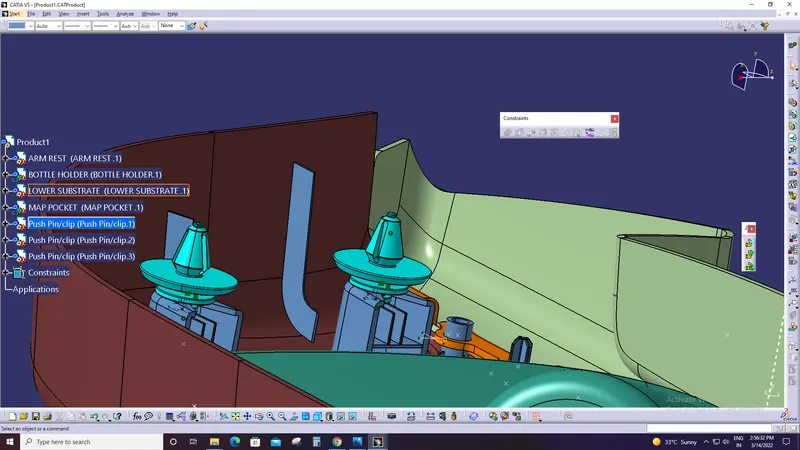
PUSH PIN:
The push pins are used for fastening or joining two objects which is made up of plastic
The below image shows the push pin .The push
pins are created by extracting the given part body and make them a solid body.
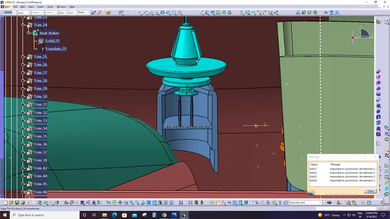
To assemble the push pin in to push pin hole on the top of dog house
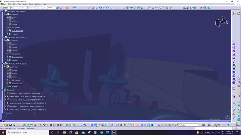
to use the production work bench .The constraint tools bar is used in that afer that the push pin given in line
existing componet option insert the part in door trim and placed the coincidence constraint tools is used and the part of the coincidance with dog house centre axis and the two part is coincidence and also i used contact constraint with the required place the final the push pin insert with the dog house up to rib guide level
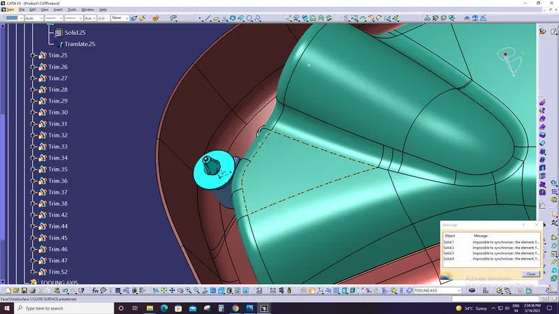
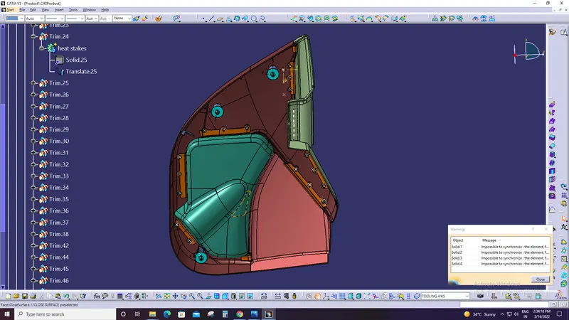
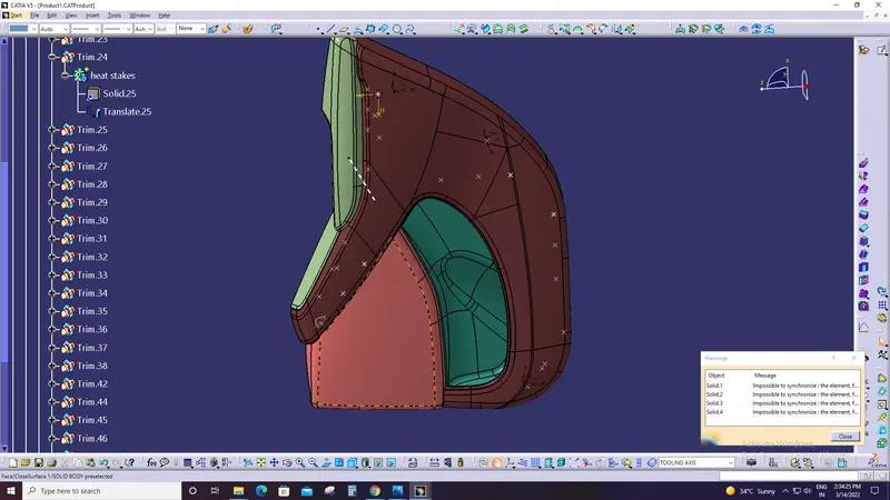
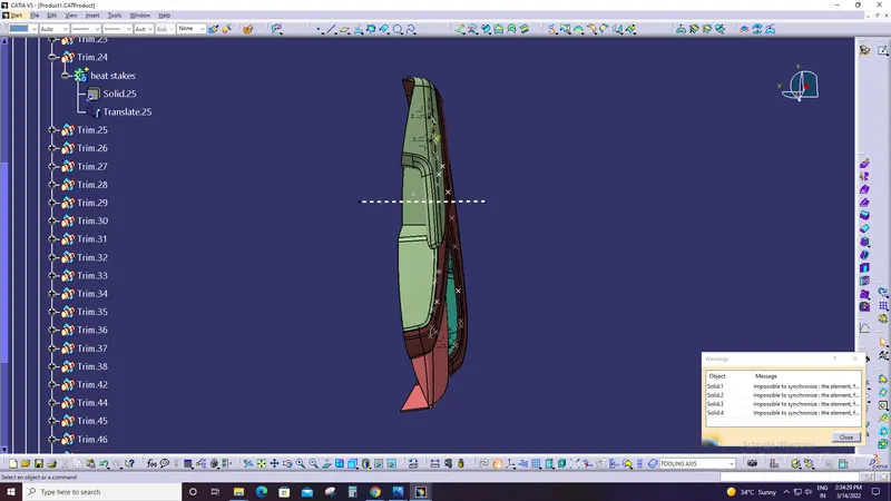
The Interior trim of the Car interior door trim is designed using the given A Class Surface as the Input and B and C Class Surfaces are created with respect to the A Class Surface
By using the given Master section attachment features i.e., Ribs and doghouse, flanges
and push clips created considering all the design rules for creation of Ribs and Doghouse.
Also carried out the draft analysis to checkwhether the Component is easily manufacturable or not with the given draft of 3 degrees for the surfaces and 0.5 degrees.
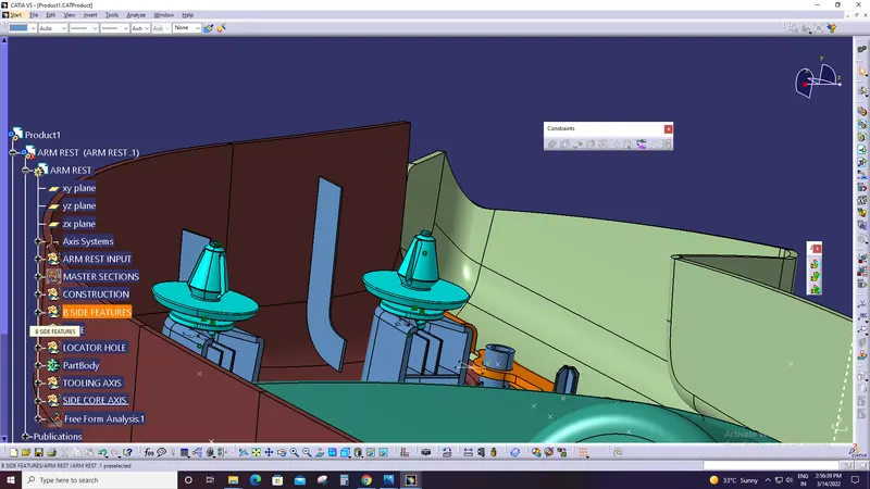
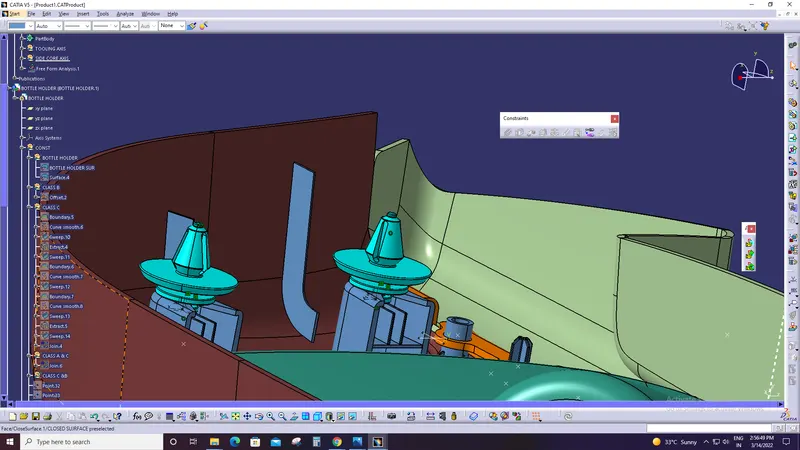
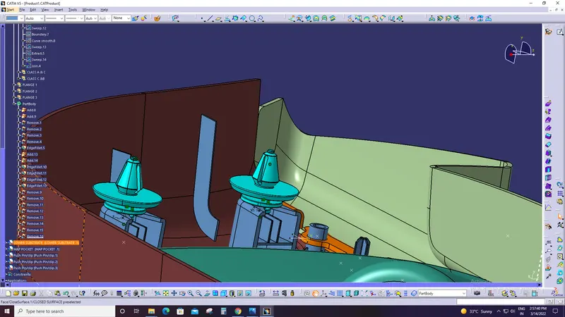
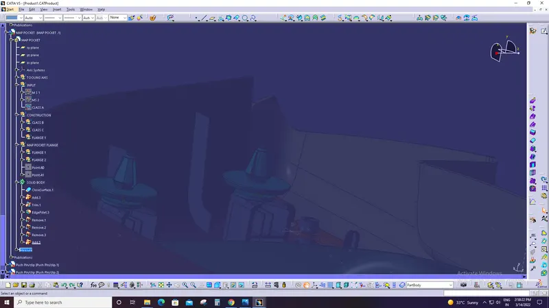
TREE STRUCTURE