Week 11 - Final project
AIM:
To design a CAD model of a door trim panel by creating class A, B and C surfaces, tooling axes and B side features for attachment purposes with the help of given inputs and master sections.
INPUTS:
Class A surfaces, master sections for B side features and flanges, and push pin clip are given as inputs for creating the model.
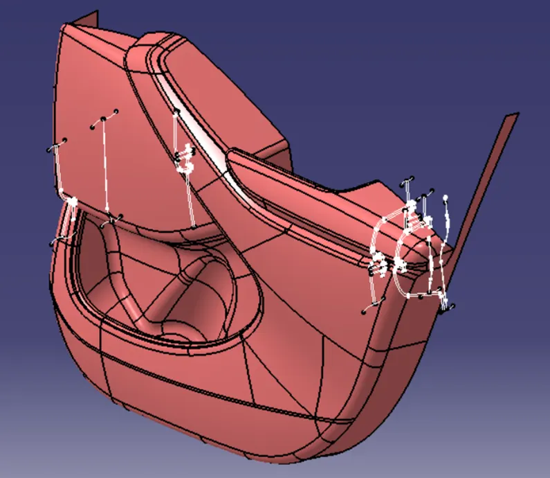
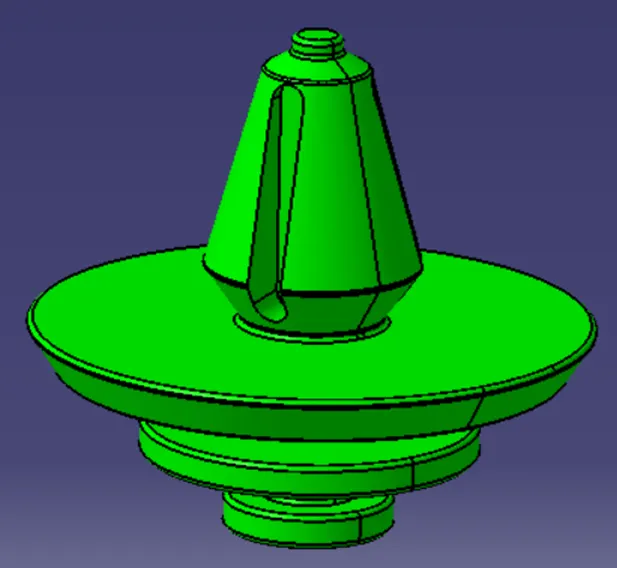
Before creating the tooling axes, we have to make sure that the given class A surface is smooth and does not have any boundary in the middle of the surface.
CREATION OF TOOLING AXES:
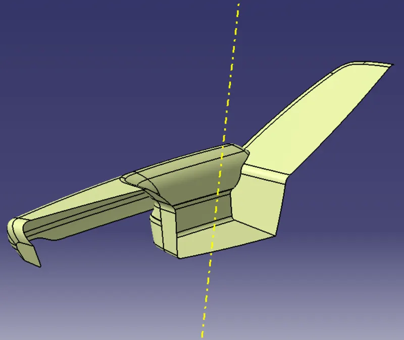
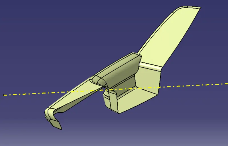
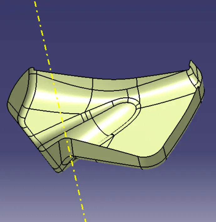
Tooling axes are created by drawing a perpendicular line or by bisecting method depending upon the geometry of the components.
DOOR ARM REST:
MAIN TOOLING AXIS:
SIDE CORE TOOLING AXIS:
MAP POCKET:
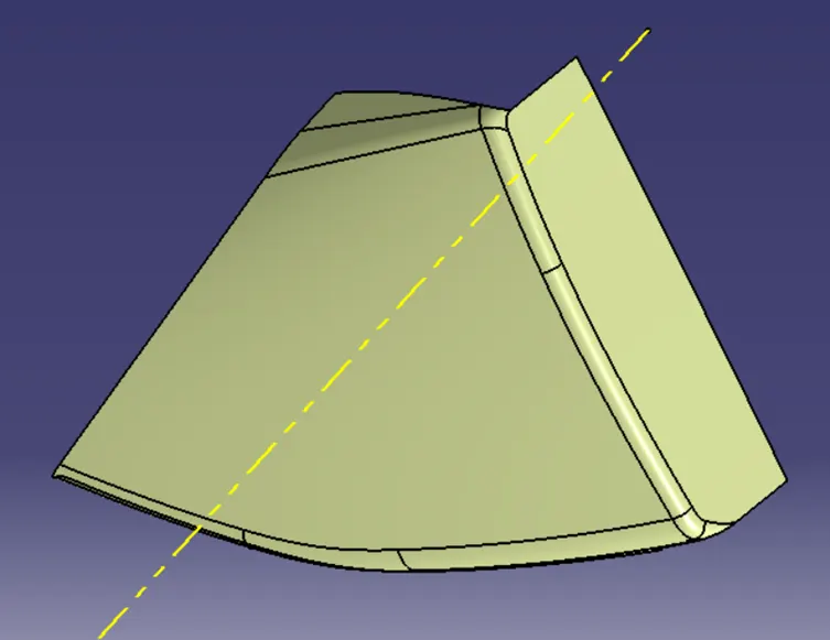
LOWER SUBSTRATE:
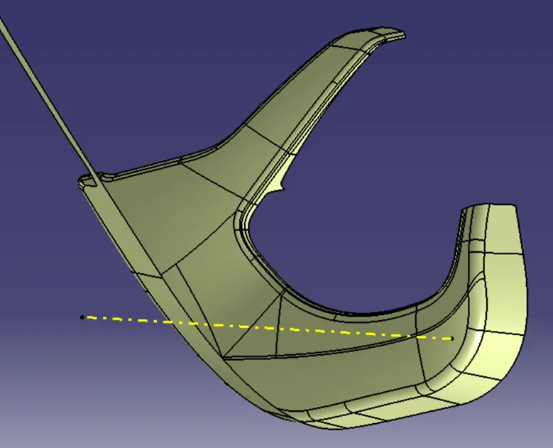
This is the initial tooling axis
BOTTLE HOLDER:
DRAFT ANALYSIS ON CLASS A SURFACE:
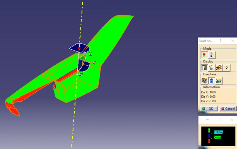
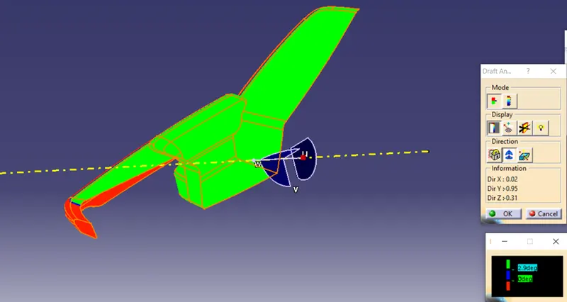
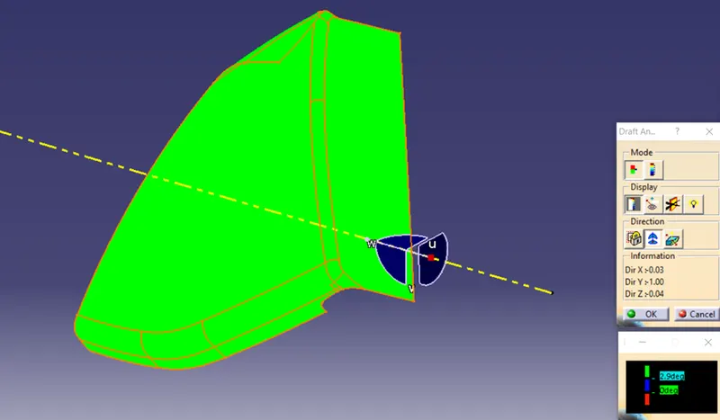
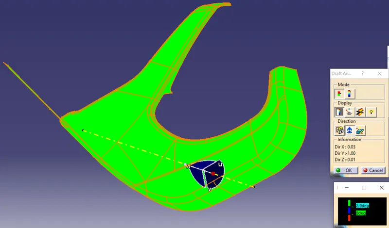
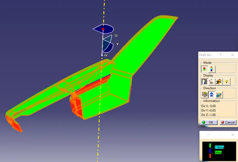
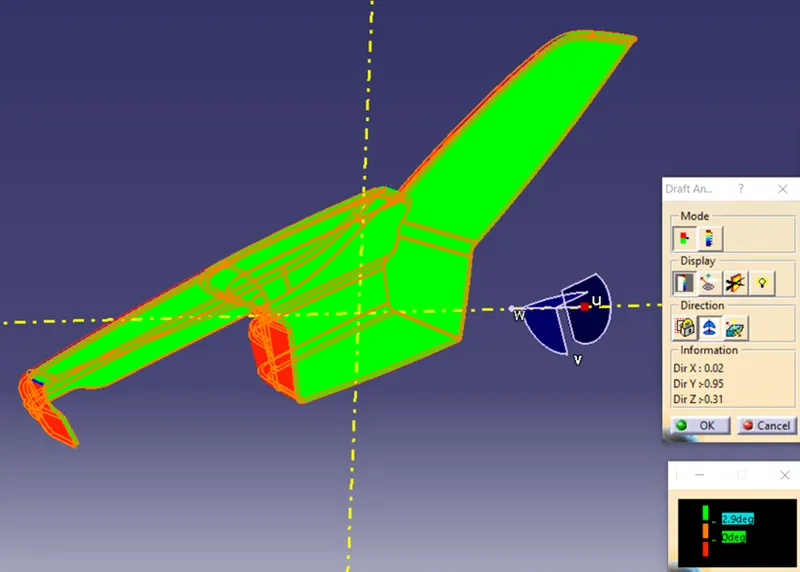
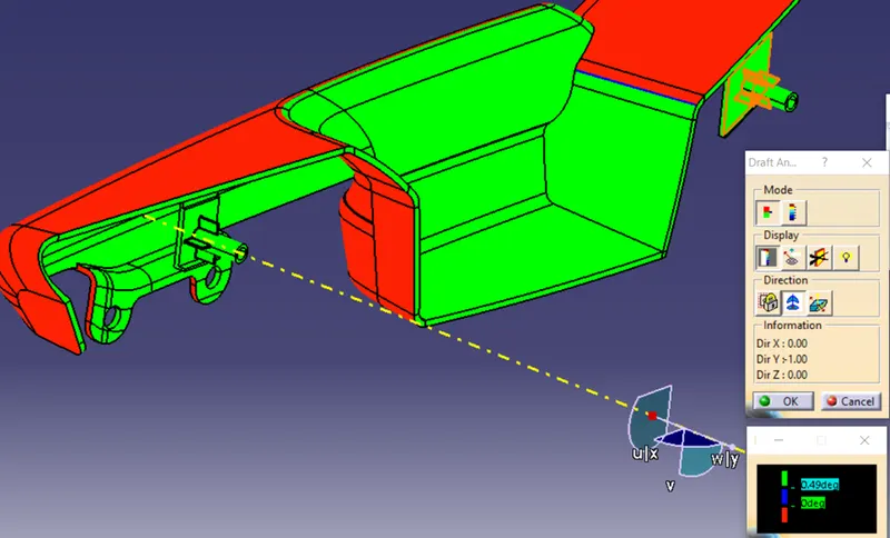
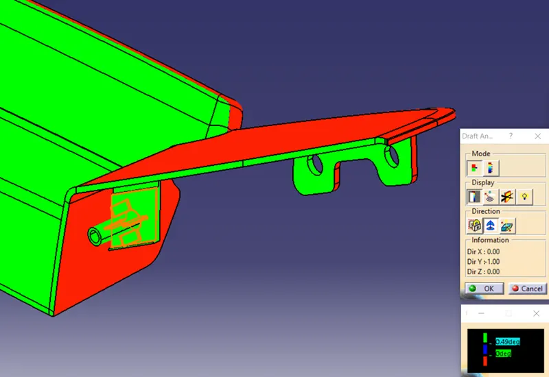
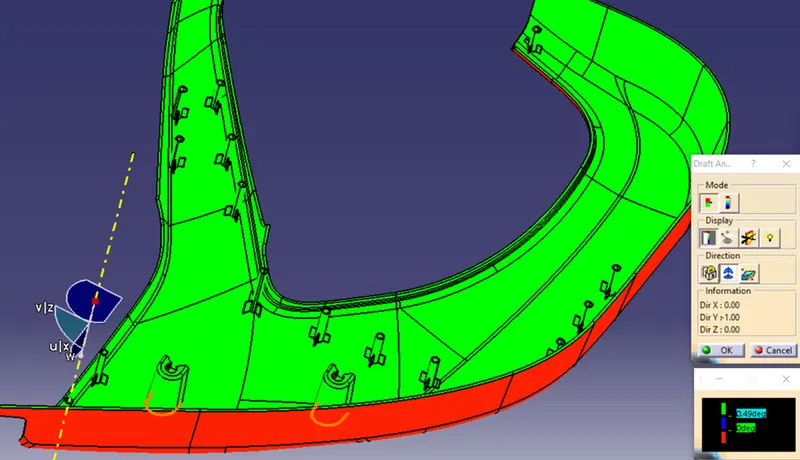
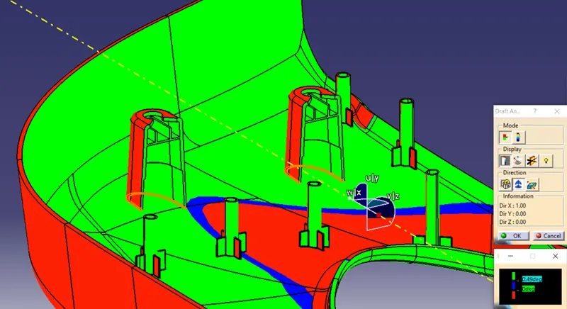
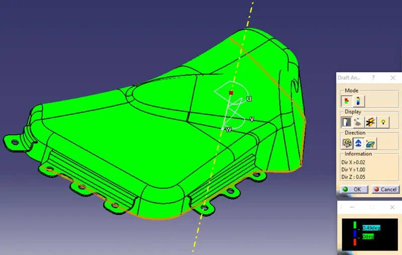
Draft analysis is done on the class A surfaces along the tooling direction at angle of 3 degrees. Blue and green colors indicate the positive draft while the red color indicate the negative draft.
DOOR ARM REST:
MAP POCKET:
LOWER SUBSTRATE:
BOTTLE HOLDER:
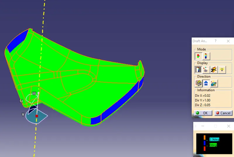
The blue area indicates that the draft is positive and less than 3 degrees. So class A should be modified.
CLASS B SURFACE:
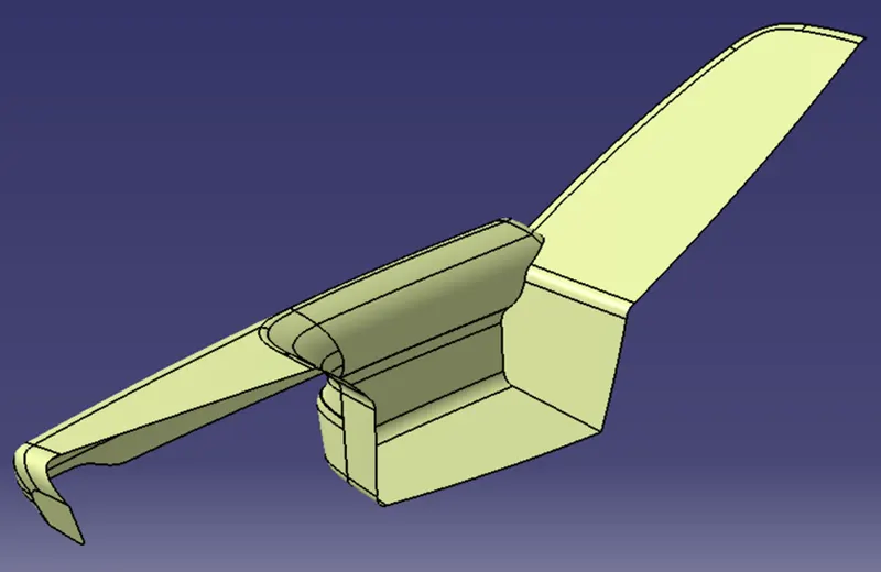
Class B surfaces are created by offsetting the class A surfaces to a distance of 2.5mm inwards. If there is any patch while offsetting, we have to solve it by using options like multi-section surface, blend or fill and finally join with the main surface.
DOOR ARM REST:
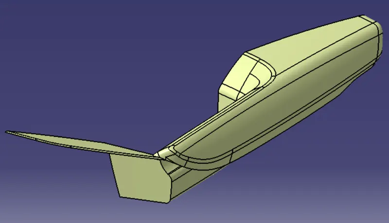
MAP POCKET:
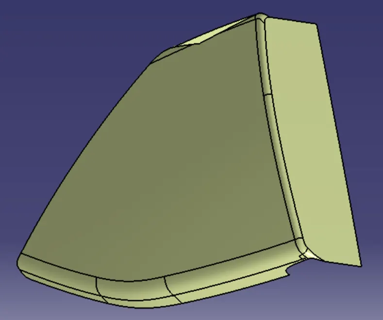
LOWER SUBSTRATE:
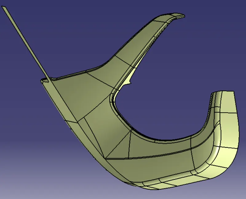
BOTTLE HOLDER:
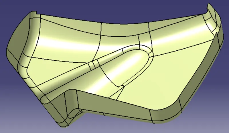
CLASS C SURFACE:
Class C surface is created by sweeping the boundary of class A surface along the tooling direction at angle of 3 degrees or normal to the surface depending upon the geometry of the components.
DOOR ARM REST:
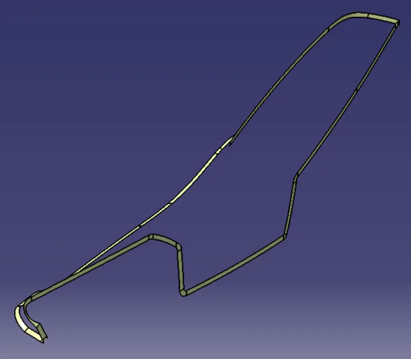
MAP POCKET:
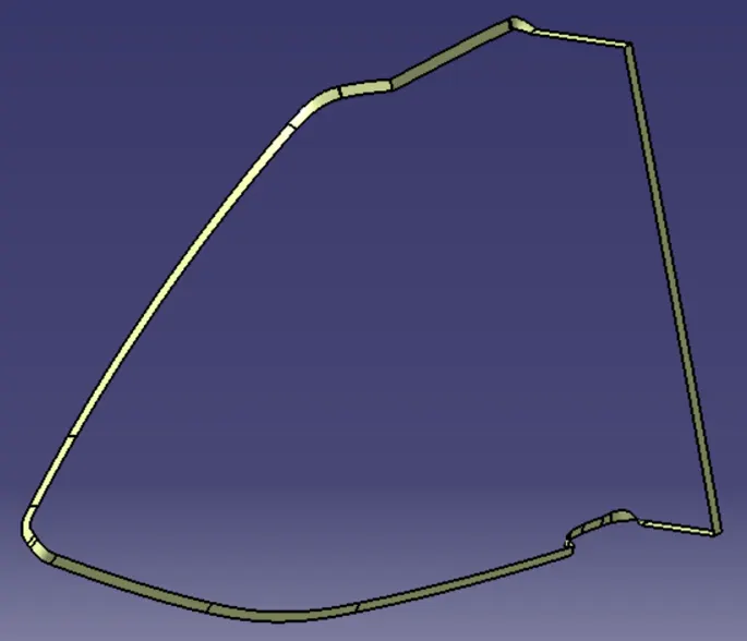
LOWER SUBSTRATE:
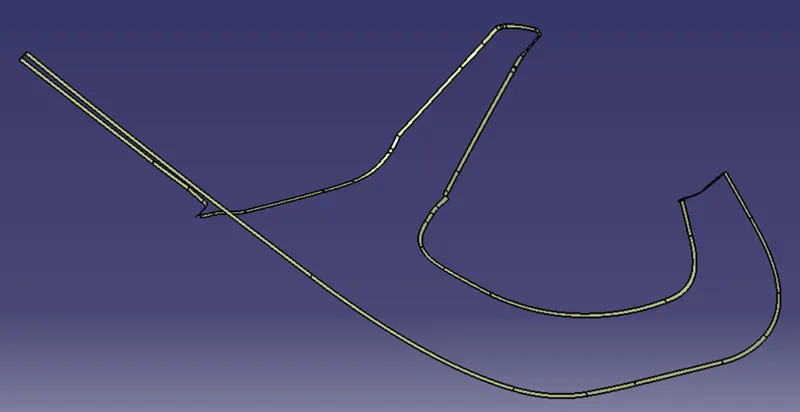
BOTTLE HOLDER:
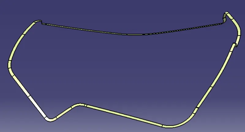
FINAL TRIMS:
Finally, the class A, B and C surfaces are trimmed or joined together. If there is any error, we have to extrapolate the edges and trim them together and make sure that there is no boundary.
DOOR ARM REST:
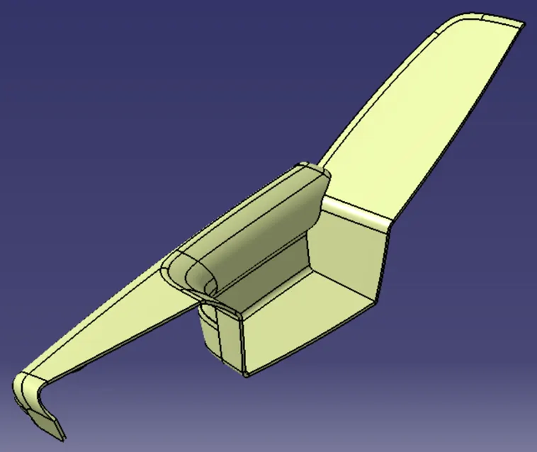
MAP POCKET:
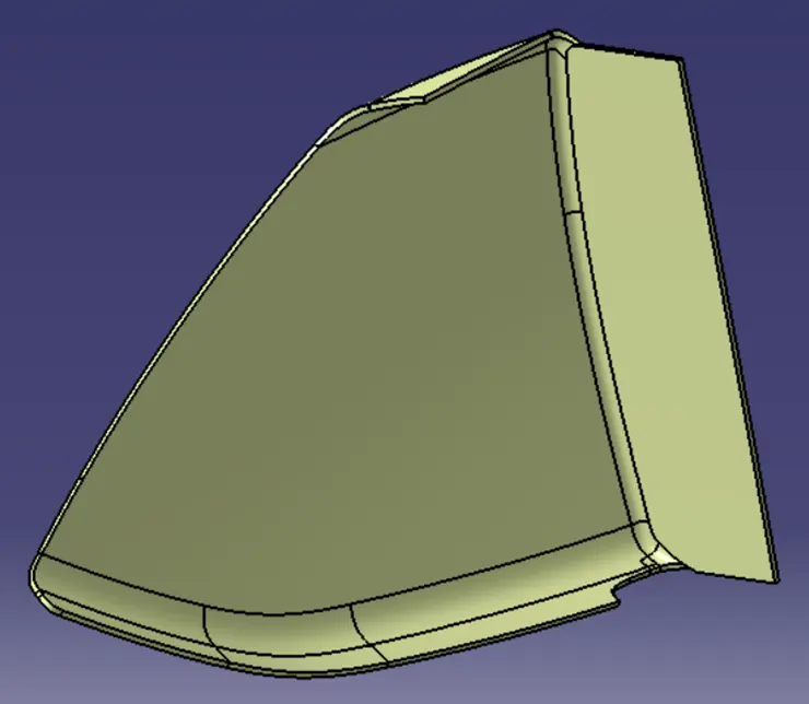
LOWER SUBSTRATE:
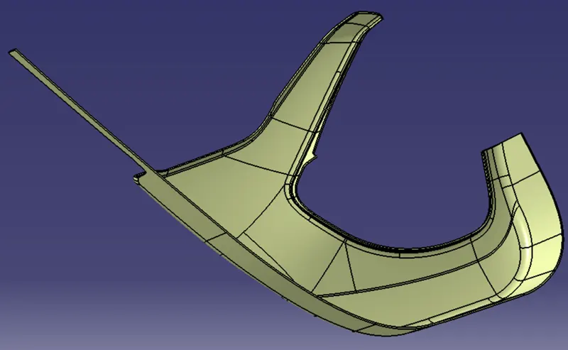
BOTTLE HOLDER:
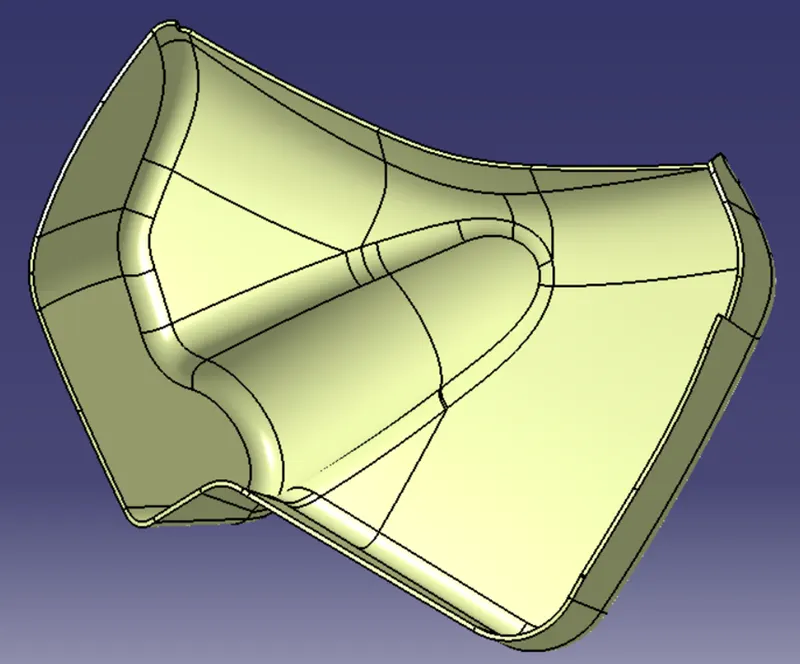
PART BODY:
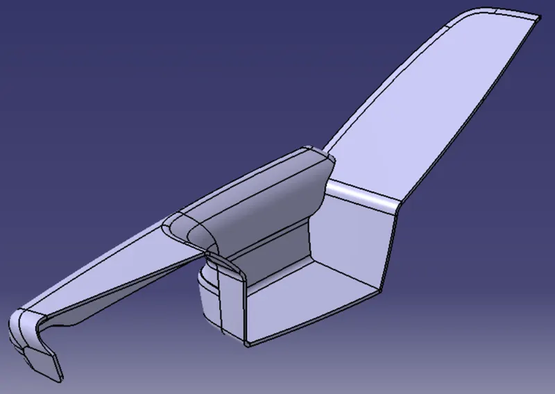
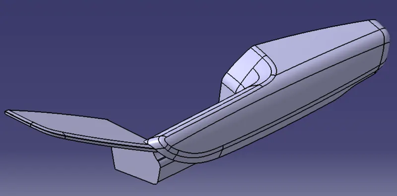
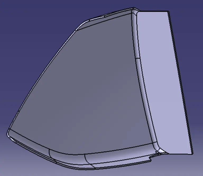
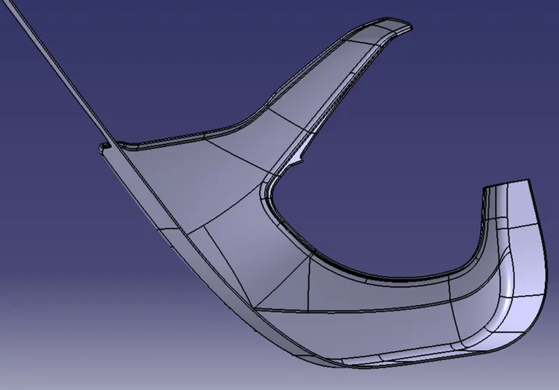
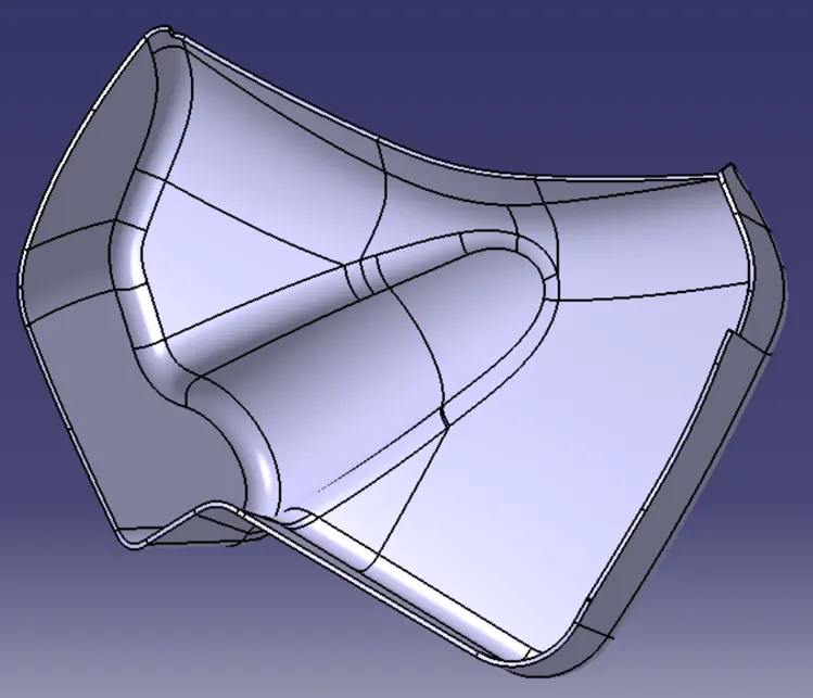
The final trims are made to solid bodies by using the close surface command.
DOOR ARM REST:
MAP POCKET:
LOWER SUBSTRATE:
BOTTLE HOLDER:
DRAFT ANALYSIS ON PART BODY:
DOOR ARM REST:
MAP POCKET:
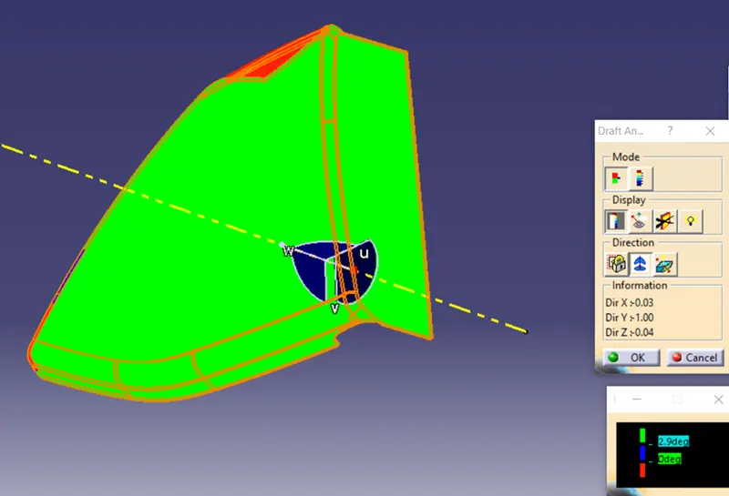
Here some part of the class C surface has negative draft. So, either class C or class A surface should be modified.
LOWER SUBSTRATE:
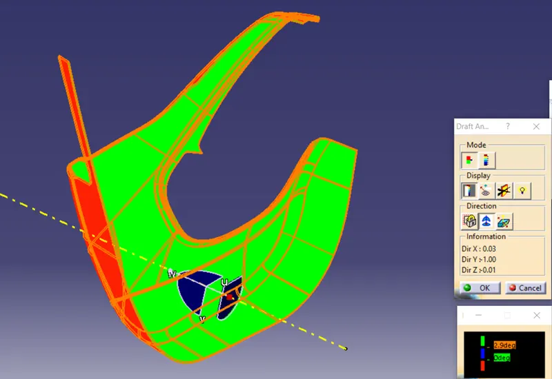
BOTTLE HOLDER:
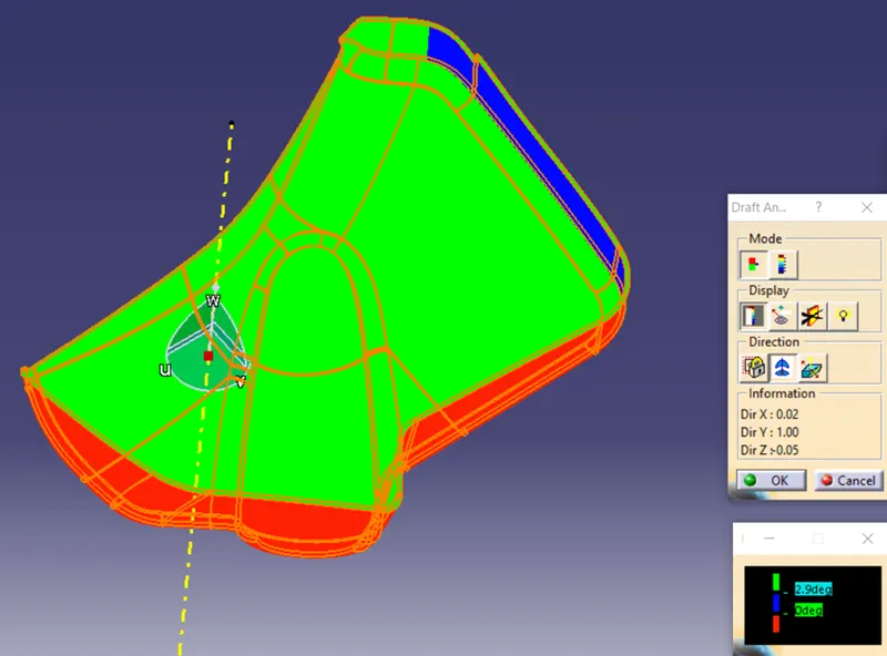
As mentioned earlier, some part of the class A surface has a draft angle less than 3 degrees. So, it should be modified.
B SIDE FEATURES:
HEAT STAKES:
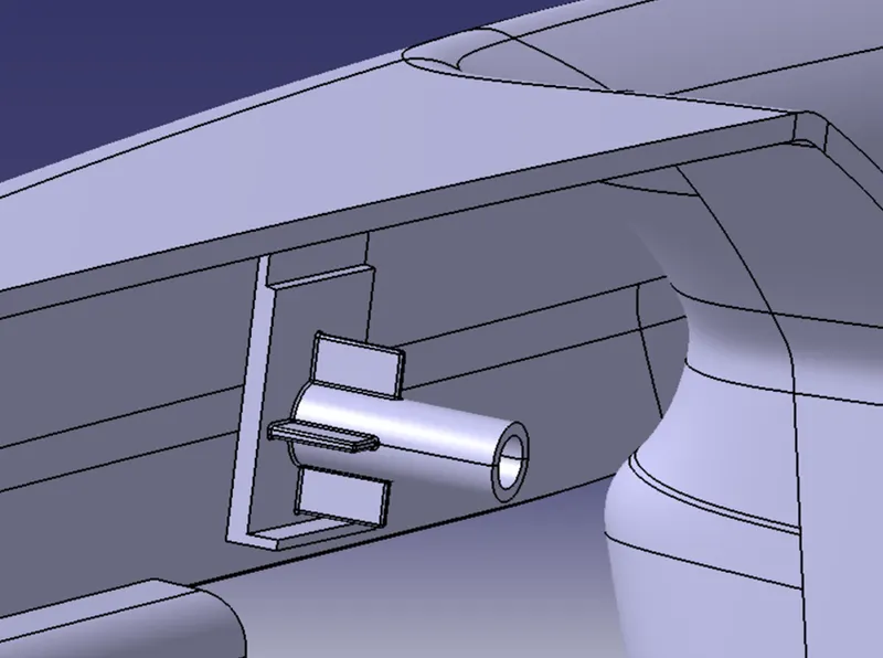
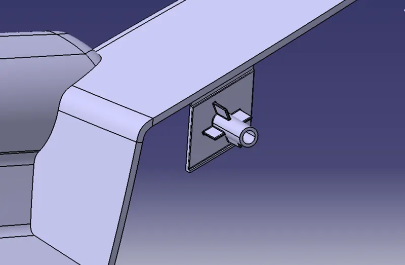
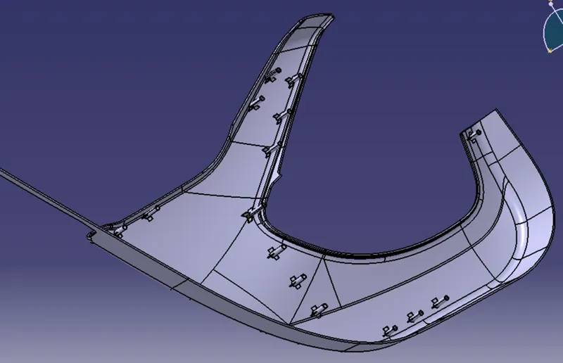
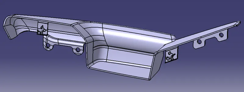
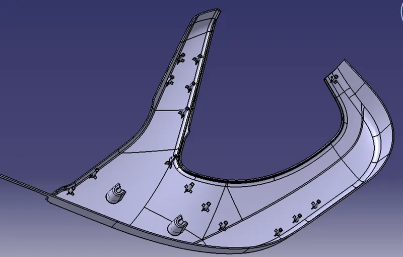
Heat stakes are used to join two similar or dissimilar parts together. These are created by using the master sections as references for dimensions and create wherever required. The minimum gap between two heat stakes should be 50mm. First we have to create a sketch on a plane, extrude it and use thick or close surface. Then fillets and drafts are applied to the heat stakes along the tooling direction. Ribs are provided at the bottom of the heat stakes for support.
DOOR ARM REST:
LOWER SUBSTRATE:
FLANGES:
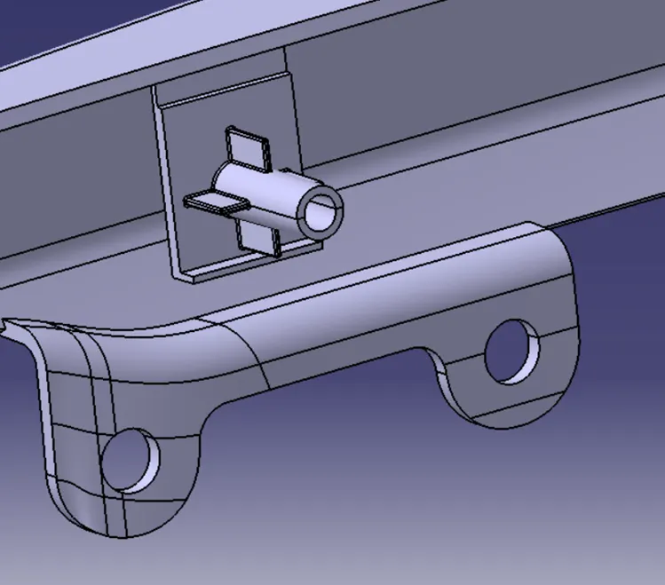
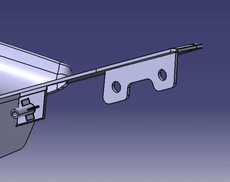
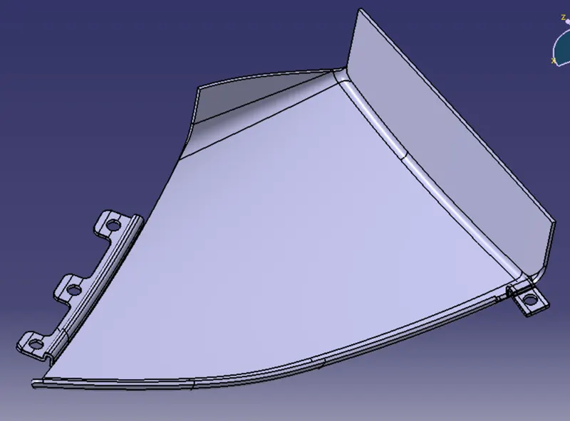
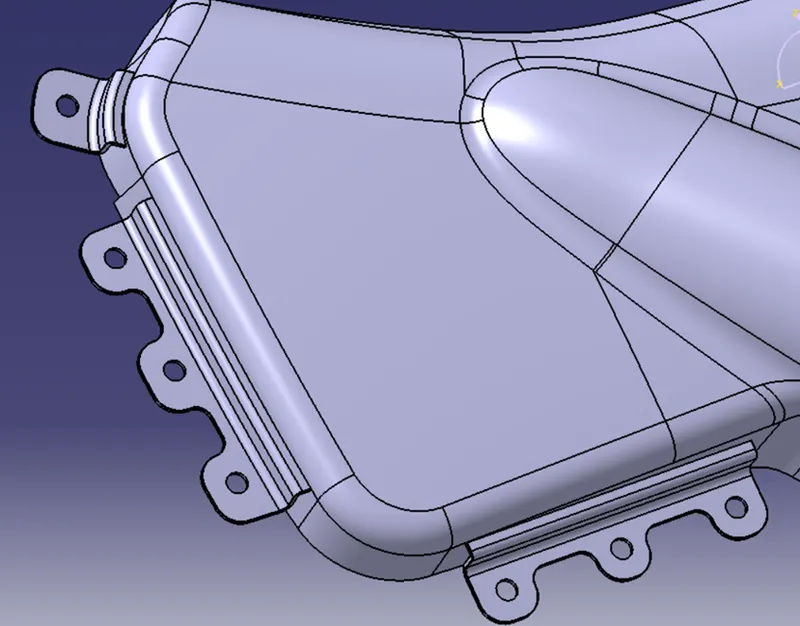
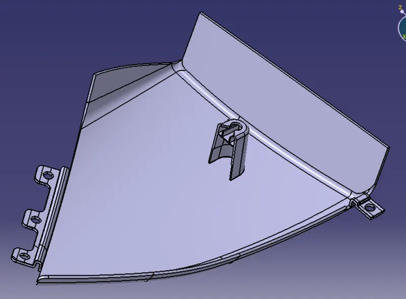
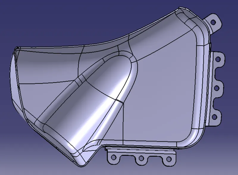
Flanges are created for holding the heat stakes by providing slots for the heat stakes and thereby connecting two parts together. Some flanges are created by extracting the lines from master sections and sweeping it. Some flanges are created by using sketch and sweeping it along the part. Slots are created for the heat stakes and unwanted parts are removed. Finally fillets and drafts are provided along the tooling direction.
DOOR ARM REST:
MAP POCKET:
BOTTLE HOLDER:
DOG HOUSE:
DOOR ARM REST:
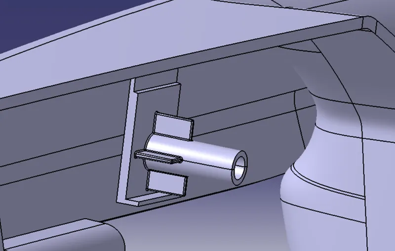
Here dog house is created to change the orientation of the heat stake and provide support to it.
MAP POCKET & LOWER SUBSTRATE:
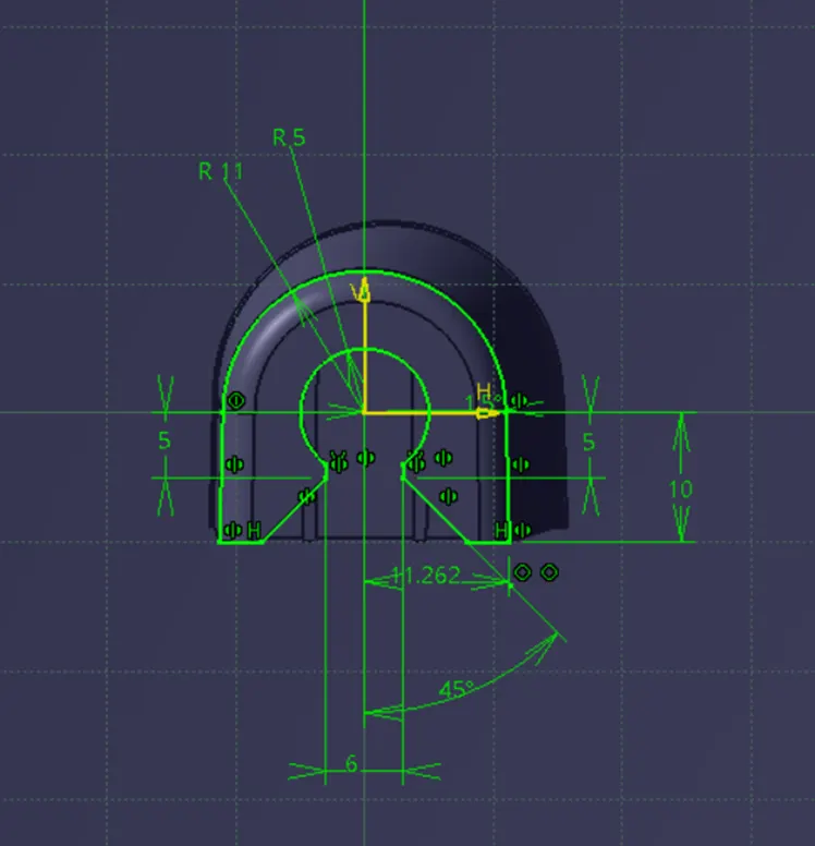
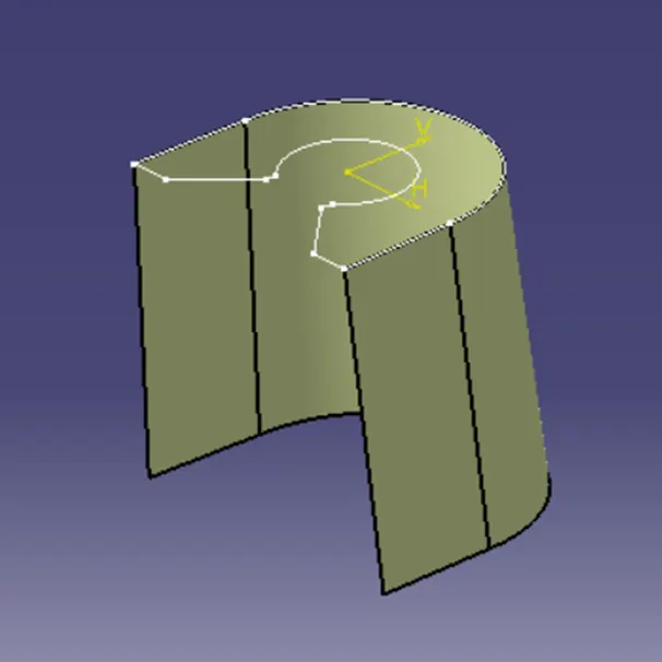
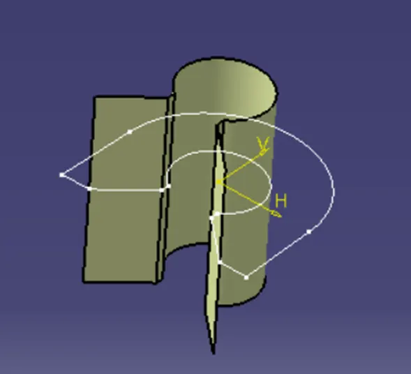
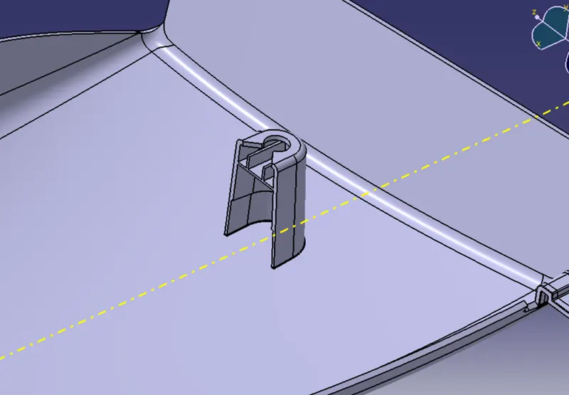
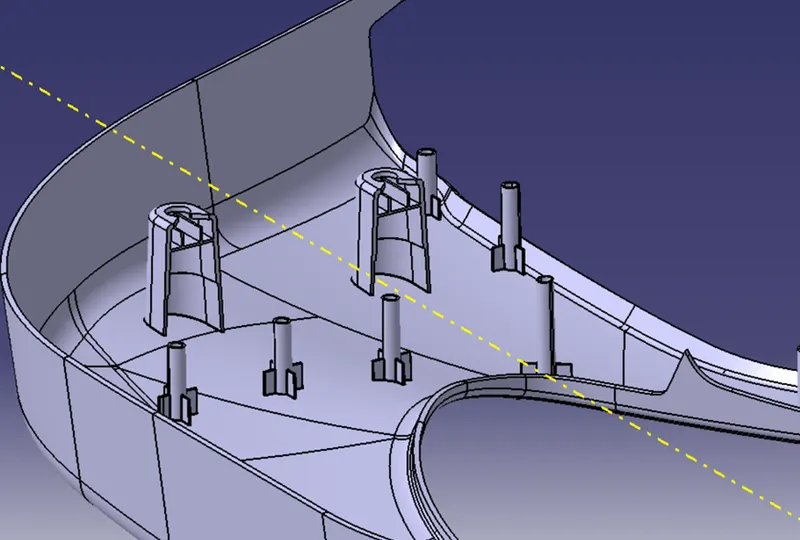
Here dog house is created to hold the push pin clip at an increased height in order to fix the part with door panel. Dog house is created as per the dimensions given in the blueprint. The bottom portion should have a thickness of 40% less than the main wall thickness. Lifter axis is created for the interior of the dog house. Then fillets and drafts are provided along the main tooling axis and lifter axis.
USES OF PUSH PINS:
- Easy to assemble the parts
- Reduce the assembly time
- No special tools are required to install
PART BODY WITH B SIDE FEATURES:
DOOR ARM REST:
MAP POCKET:
LOWER SUBSTRATE:
BOTTLE HOLDER:
DRAFT ANALYSIS ON PART BODY WITH B SIDE FEATURES:
DOOR ARM REST:
MAP POCKET:
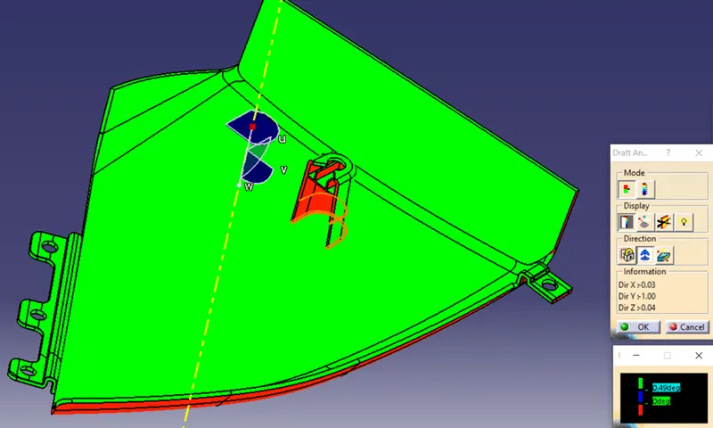
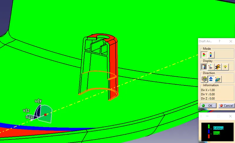
LOWER SUBSTRATE:
BOTTLE HOLDER:
FINAL ASSEMBLY:
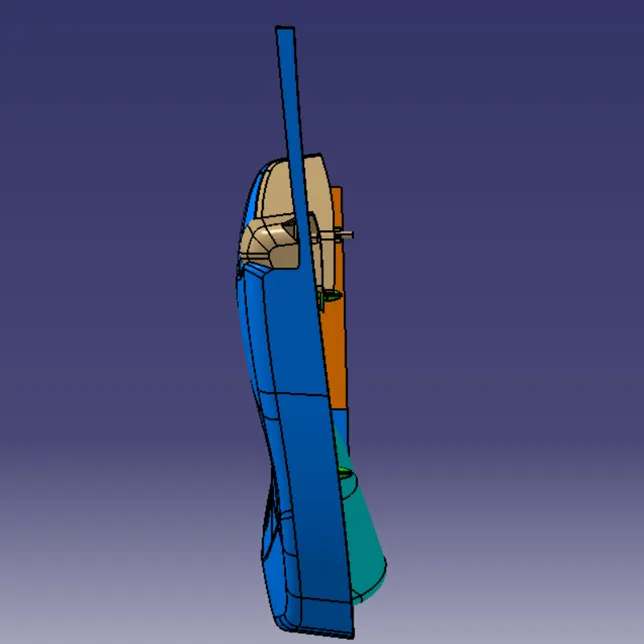
Then all the parts are assembled and push pin clips are inserted and assembled on the top of the dog house created by using assembly constraints.
FRONT VIEW:
TOP VIEW:
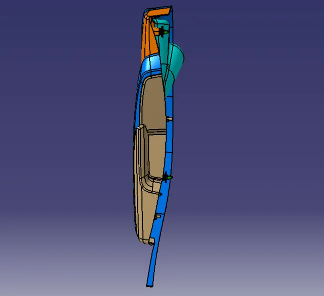
RIGHT VIEW:
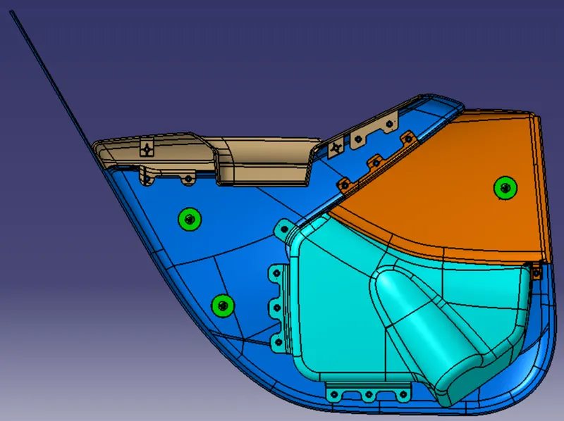
LEFT VIEW:
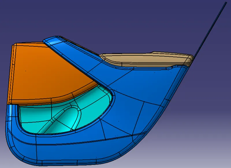
ISOMETRIC VIEW:
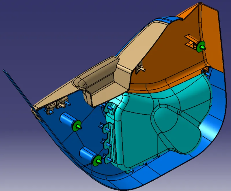
CONCLUSION:
Thus the door trim panel is designed with class A, B and C surfaces and B side features by using the given inputs as like in OEM and tier 1 companies and also draft analysis is performed on it.