Week 11 - Final project
Modelling of Automotive Interior Door Trims, and Designing the B
Side Features
Introduction -
Trims are basically Plastics which are designed by an Automotive Plastics Engineer who
is having knowledge of Plastics, how can it be manufactured, how can it be fixed with other
components (BIW mainly, BIW - Body in White is a sheet metal part where plastics are fixed
on), and this is the primary reason why designing plastics is more challenging than making the
Class A surfaces, which are the Aesthetic Surfaces.
These TRIMS (Plastics) carry engineering features viz, Flanges, Heat Stakes, Dog
Houses, Bushes, Push Clips, Push Pins etc. which required deep study and long time to create
and after that that, there are Design Considerations which are important and must be taken
care of in order to make the part feasible and manufacturable.
These all design these considerations are used in this project and the same has been
explained.
Master Section -
In the industry, when there is Designing of a new part for the car or Re- Designing the
same, there are so many considerations which are taken care of with the help of Master
Sections. This consists very important information. On the basis of Master section, the whole
design is caried out.
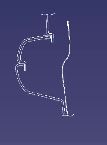
Master Sections are 2-D sketches (lines and curves) which are made by an Expert, and
requires very high skill level to create it. This consists all the data like, Fixation, Packaging,
Clearance (all the important placement distances), and Feasibility. We have also provided
master sections for the B - Side features which we will be using for various purpose.
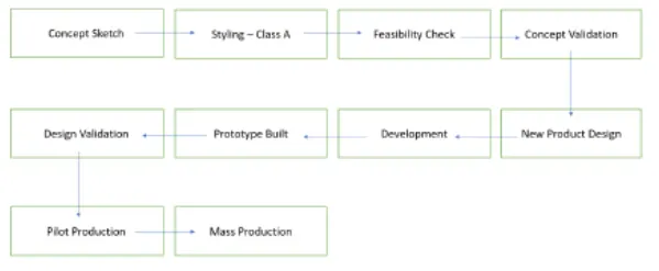
in OMEs there are various stages when there when a new IDEA is carried out to reality,
consider the images shown below
Methodology-
To start with, we are having parts for the Door which we have to make it and after
that it will get assembled together individually with eath other, and after that as a whole
componenet (Door) to the BIW.
As discussed above, master section takes care of all most every things and parameters,
for this project we are having data of Fixation, we have given Class A surfaces of various parts,
as well as a Master Sections with which we well be making a Close body as well as design the
respective B Side features according to master sections. Wetalso need to create tooling
direction for the same, which is again, a very important factor in Plastics Design.
Tooling Direction
Tooling Direction/Tooling Axis is a Direction which defines how the Plastic will be
made. It defines some of the most important parameters viz. what will be the orientation of
the part, and How will it form. Once this is done, a mould designer will be making Core and
Cavity for the same part with respect to the main tooling direction.
Generally, it is practiced to make the tooling direction Vertical/Normal (90 degrees)
to the surface/face. Which is ideal condition. But in some cases due to undercuts or -ve drafts,
tooling direction MIGHT change and form some parts, it might as well require Side Core/Lifter
axis.
B.-Side Features :
These are the feautres which we will have to make for the sake of connecting the part
with the rest of the components, weather it be another part or fixation plane or BIW (as
explained earlier). There are various features on this surface viz, Ribs, Screw Bosses, Dog
houses, etc. And information of these all are given in MASTER SECTIONS. If not then the
plastics engineer has the knowledge of BiW and can contact with the BIW team to get the
idea, and this is how it is done in OEMs.
To start the modelling we will have to take a look master sections since we are having
them. So we have to take some important parameters before actually making the part, this
contains Inspection, Measurements and Features defined in it.
For us the master section we got has below listed details
1. Thickness of the part
2.Heat Stakes.
3.Fixing Stratergy.
4.Radius
5.Drafts.
6.Flange.
Inputs :
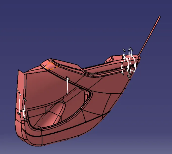
This input has four differnt parts where to be get united together
1. door arm rest
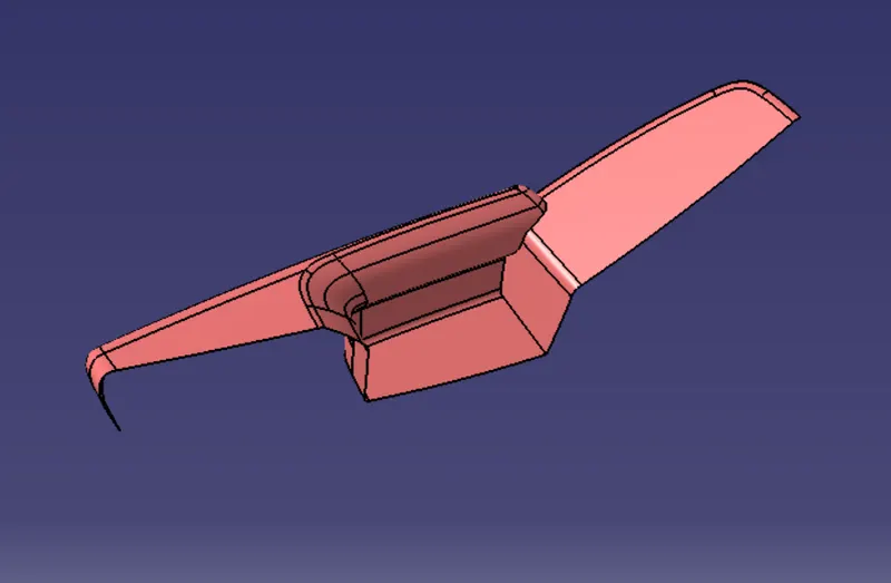
2. lower substrate
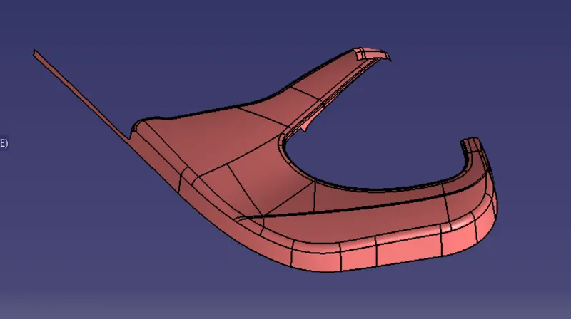
3. map pocket
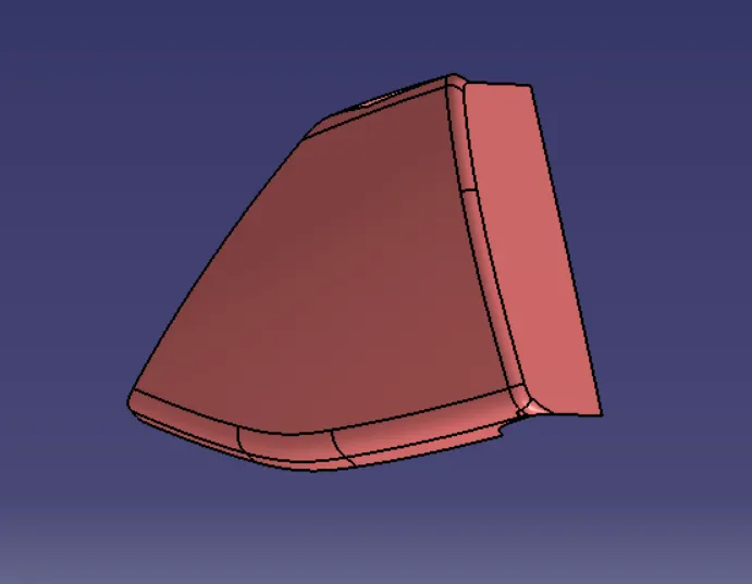
4. bottle holder
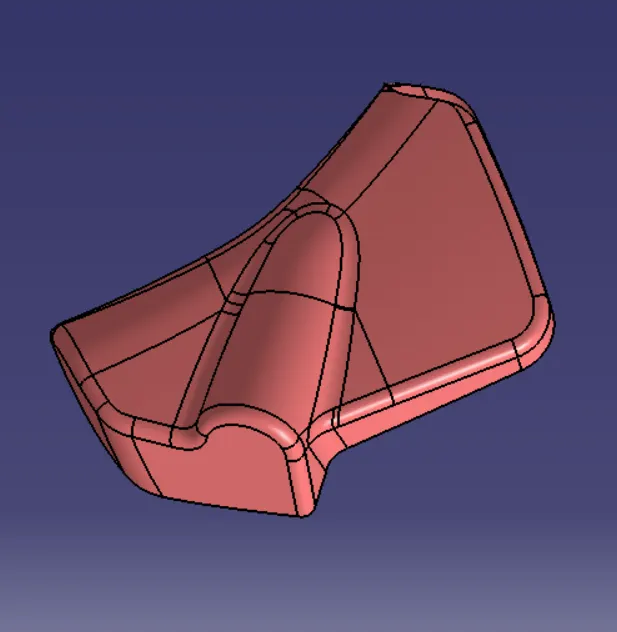
- tooling axis creation
1. door arm rest
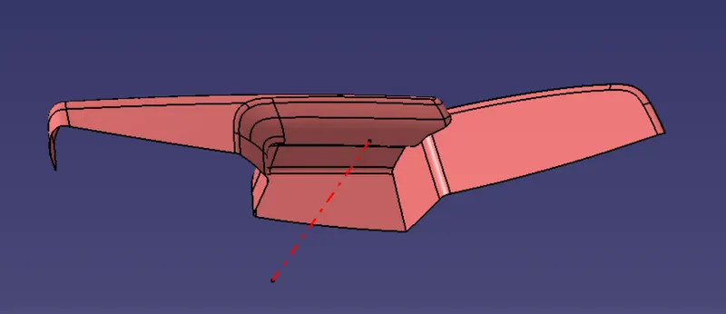
2. lower substrate
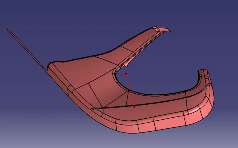
3. bottle holder
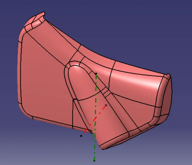
4. map pocket
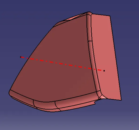
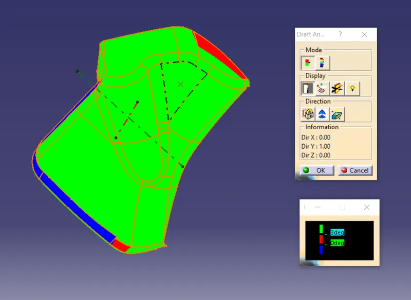
- draft analysis of class A surface
1. map pocket
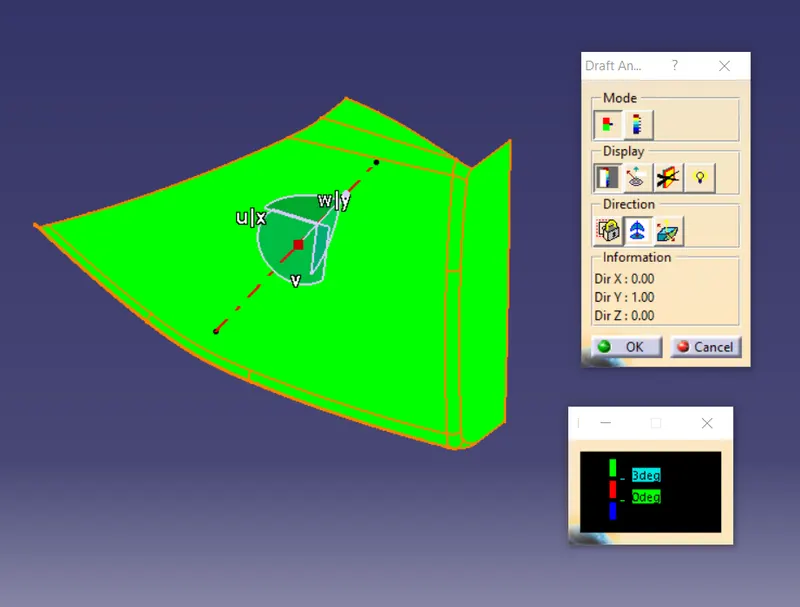
2. door arm rest
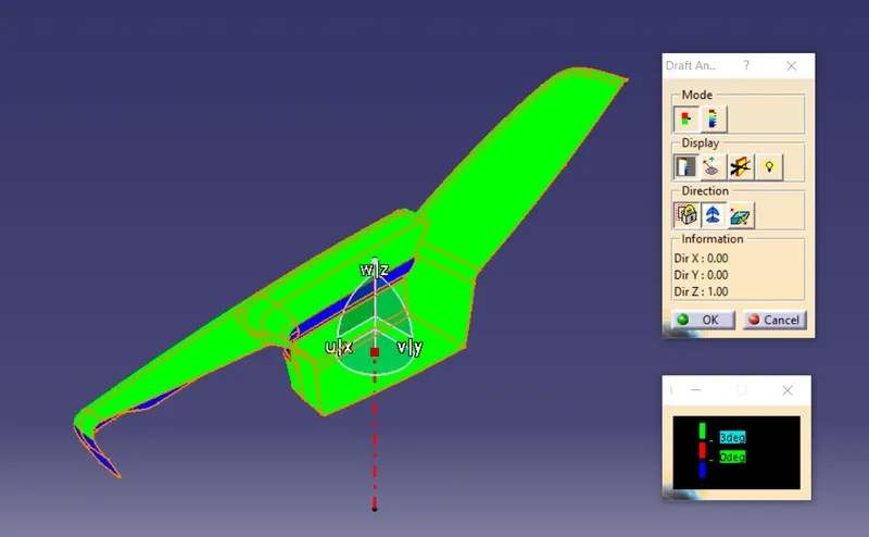
3. lower substate
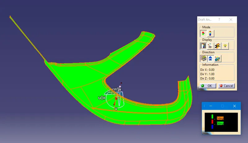
4. bottle holder
- class b surface
- extrapolate the all the edges using sweep,multisection,fill,join command to from the class A surface
1. bottle holder
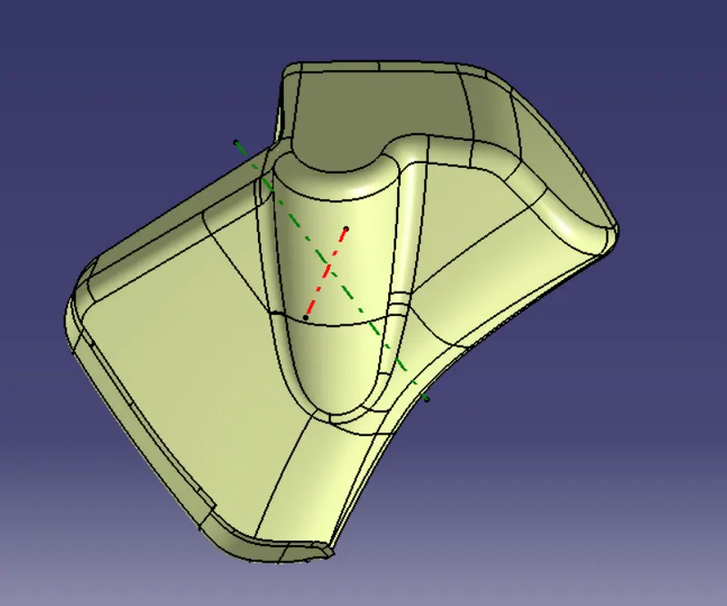
2. door arm rest
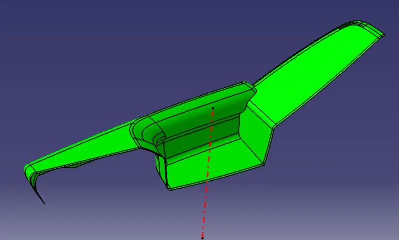
3. lower substate
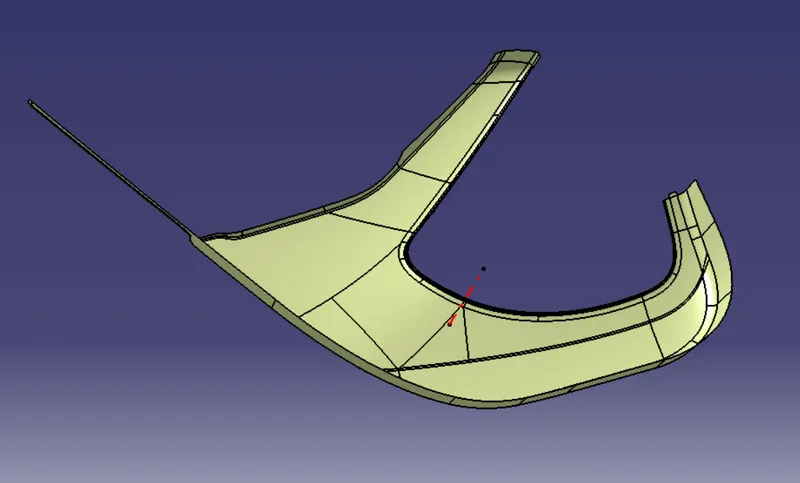
4. map pocket
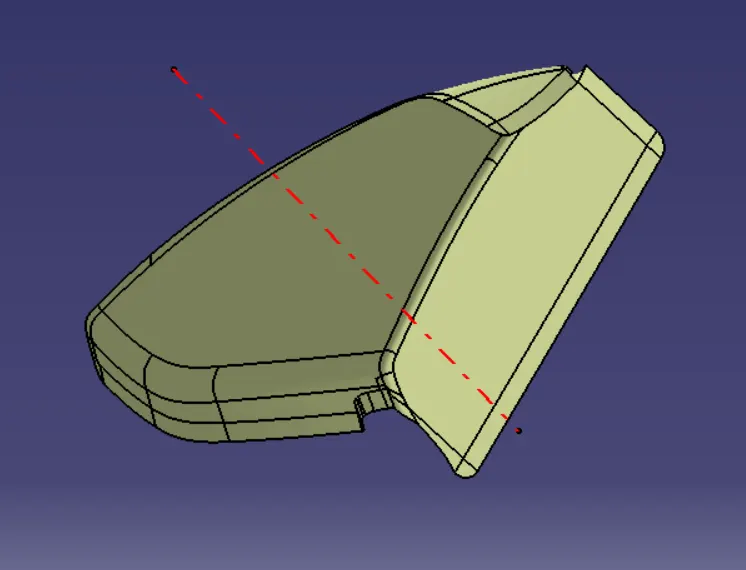
- class c surface
- make 90deg sweep surface to create the class C surface using sweep,multisection commands
1. map pocket
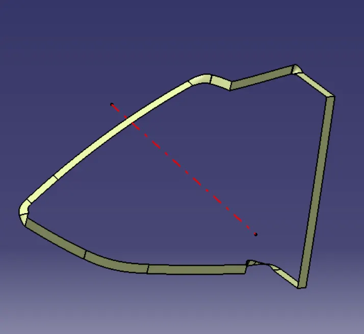
2. bottle holder
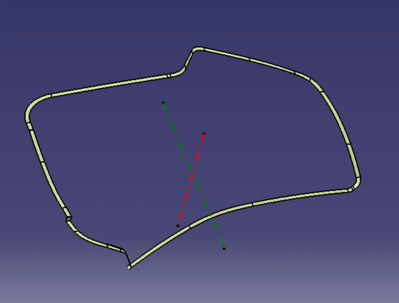
3. lower substate
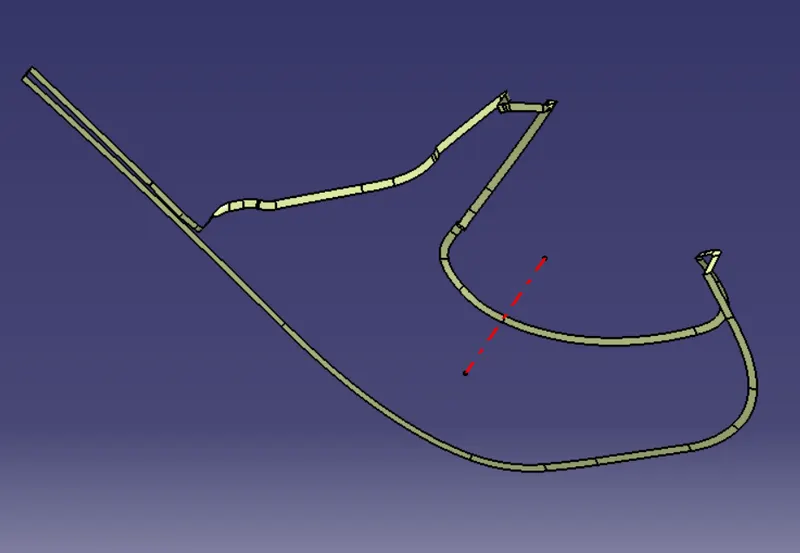
4. door arm rest
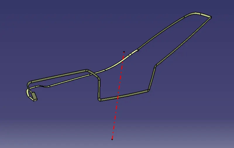
- joing class A and class C surface
1. door arm rest
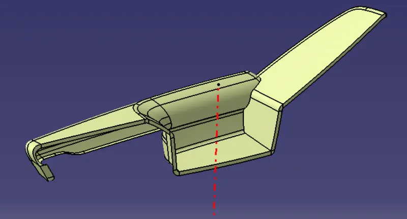
2. lower substate
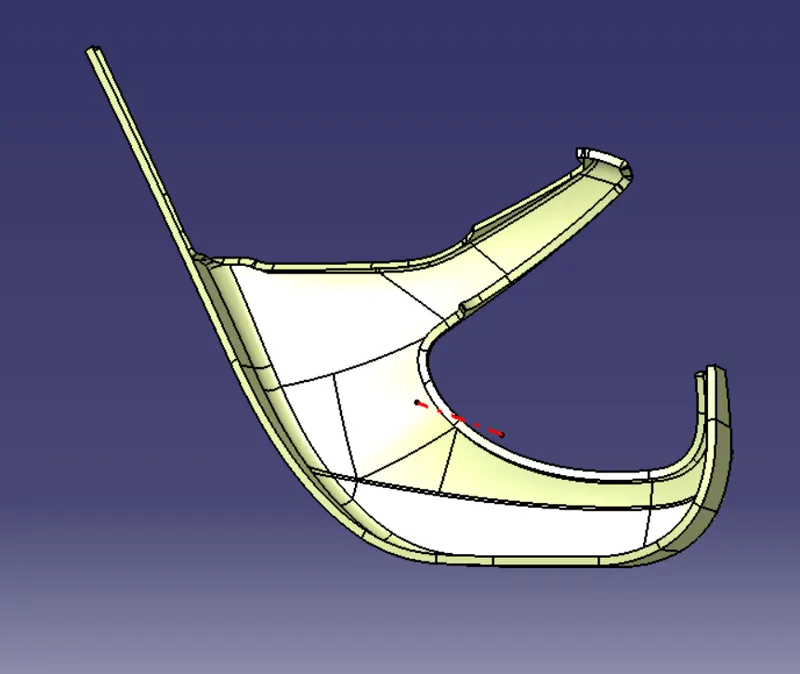
3. bottle holder
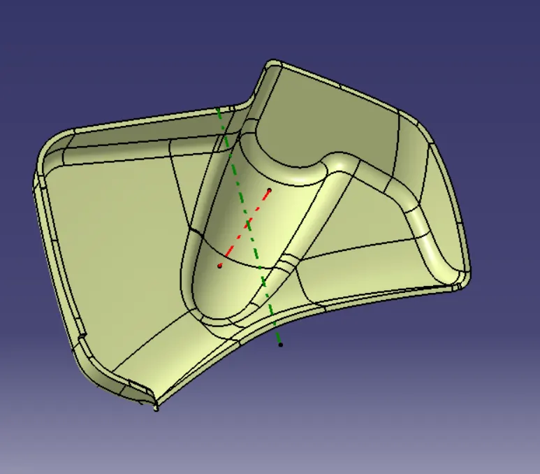
4. map pocket
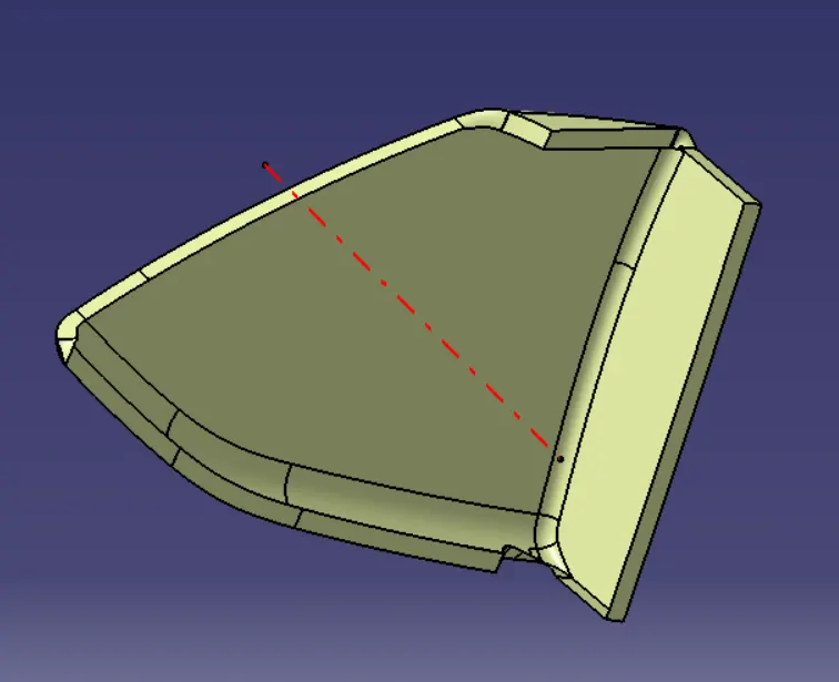
- triming class A and class C with class B
1. map pocket
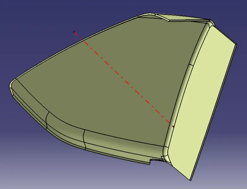
2. bottle holder
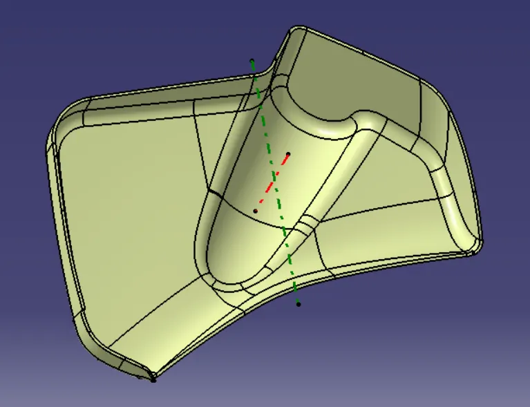
3. lower substate
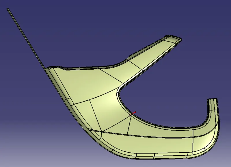
4. door arm rest
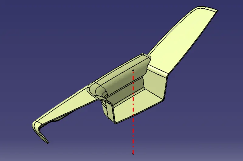
- closed part conversion
1. door arm rest
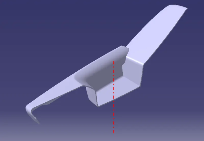
2. lower substate
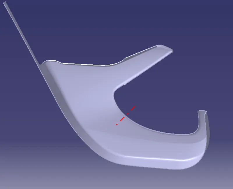
3.bottle holder
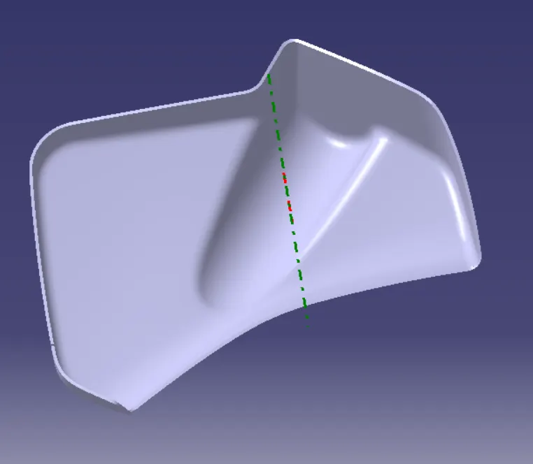
4. map pocket
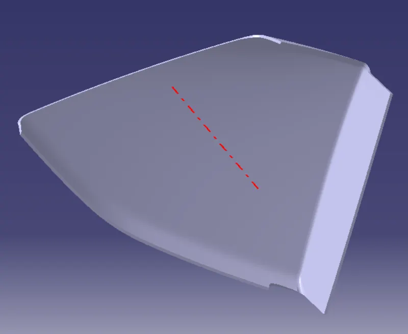
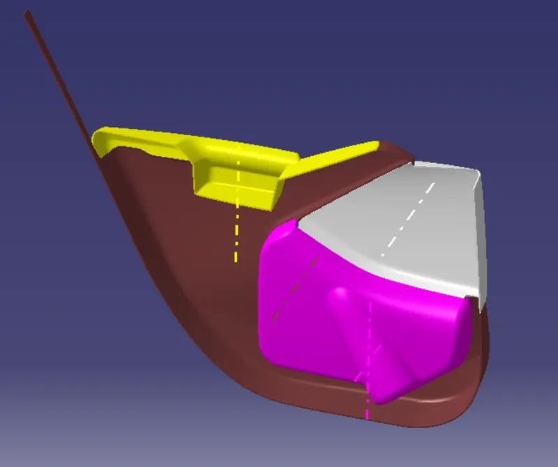
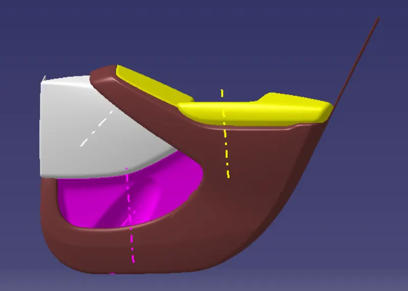
assemble parts
- master section profile creation
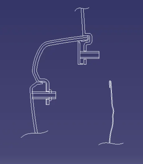
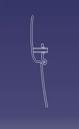
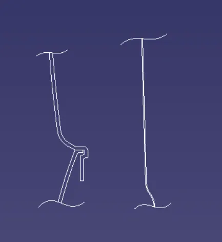
1. bottle holder
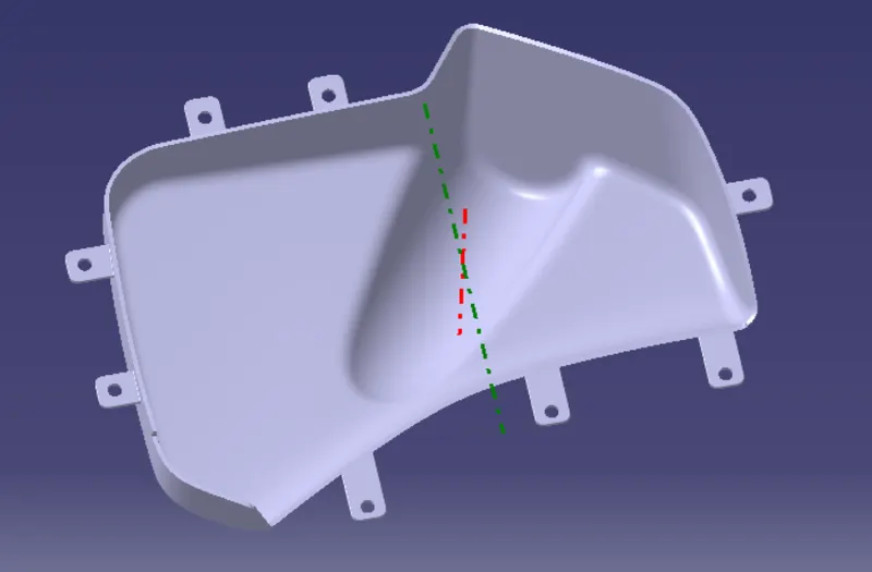
B- Side Features, as explianed above these will be made according to the Master Sections,
so we have simple flanges as well as the holes in it for the heat stakes, that we need to make,
there are two ways with which we can make the flanges,
1.Within Class A
2. Make those with Boolean operations.
Here we have opted for Boolean Operations, since we already made the Closed Body surfaces,
we can start by extracting the edges and then Extruding it then we can use the Thickned
Feature from Part workbench, and then with the help of boolean operations we can add it to
the part.
Once the flanges are done we can again perform the boolean operatiols to make the Holes,
here accoring to master sections, the heat stakes are way bigger and larger than it should be,
so we have made it according to ourselves. Consider the image,
2. map pocket
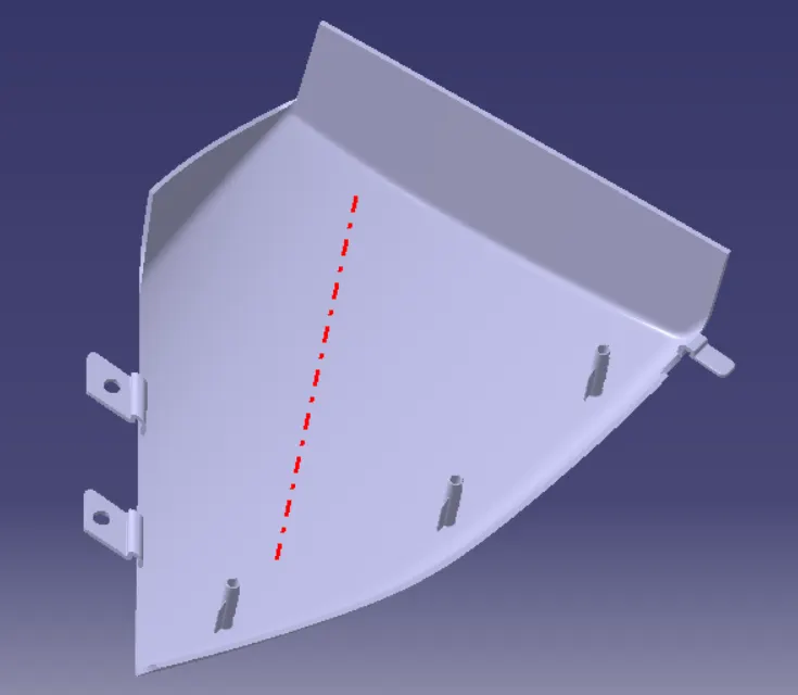
Next we make the Flanges with the same Boolean Operations, now, since this will be the
primay part which will join the LMP it needs to be HEAT STAKED so we have the heat stakes
on this part. Alos we will need this for fixation, so for that we have made the Dog House,
Screw Boss are used to connect the part via screwing medium, eg. tow components will be
screwed together but for that we will require some area for the screw to be locked on, and
this area is the Screw Boss.
Once this is done both components can be screwed. However screw bosses are generally
cylindrical, it doesn't need to be tapped. Since the screw itself can create an impression on
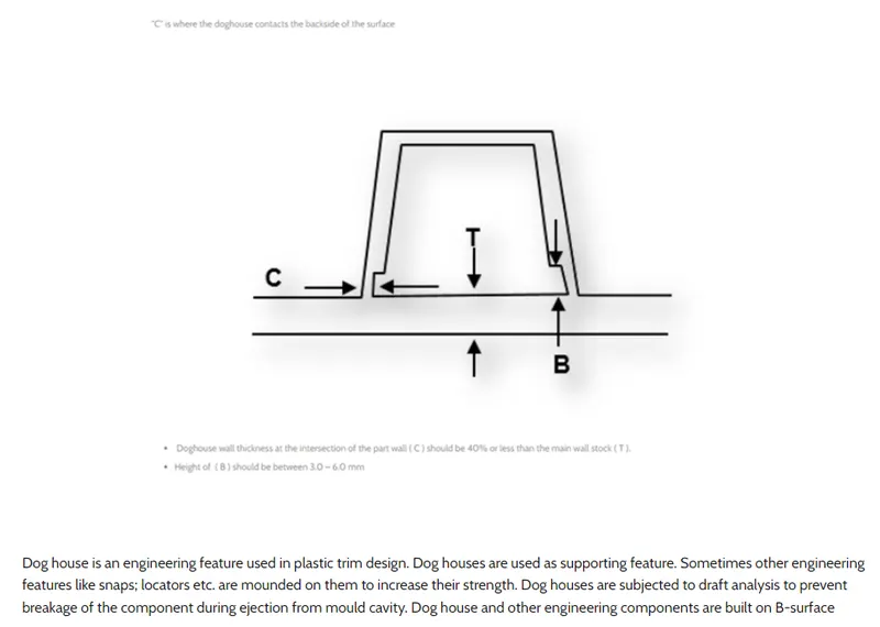
the plastic Boss. The basis function of the Dog House is to avoid SINK marks. This is needed
when the Boss we are designing is thick enough to create a Sink difect. And to avoid this
possibility we create a think feature/ decrease the thickness where the base is connected, as
shown in the figure.
Another thing is that we we have a large distance from the base (B Surface) we cannot simply
design the Boss all the way through, instead we give a Dog House to lift it, and Place the Boss
on top of the Dog House. Here as a secondary fixation we have designed Push Pins.
The final feature of creating a dog is when we require opposite or Perpendicular Boss with
respect to the tooling Direction. Then we can Create a dog house respectively and place the
Boss on top of it.
3. lower substate
Here as a secondary fixation we have designed Push Pins.
The final feature of creating a dog is when we require opposite or Perpendicular Boss with
respect to the tooling Direction. Then we can Create a dog house respectively and place the
Boss on top of it. Alos we will need this for fixation, so for that we have made the Dog House,
Screw Boss are used to connect the part via screwing medium, eg. tow components will be
screwed together but for that we will require some area for the screw to be locked on, and
this area is the Screw Boss. Once this is done both components can be screwed. However screw bosses are generally
cylindrical, it doesn't need to be tapped. Since the screw itself can create an impression on
the plastic Boss. The basis function of the Dog House is to avoid SINK marks. This is needed
when the Boss we are designing is thick enough to create a Sink difect. And to avoid this
possibility we create a think feature/ decrease the thickness where the base is connected, as
shown in the figure. Another thing is that we we have a large distance from the base (B Surface) we cannot simply
design the Boss all the way through, instead we give a Dog House to lift it, and Place the Boss
on top of the Dog House. Here as a secondary fixation we have designed Push Pins.
The final feature of creating a dog is when we require opposite or Perpendicular Boss with
respect to the tooling Direction. Then we can Create a dog house respectively and place the
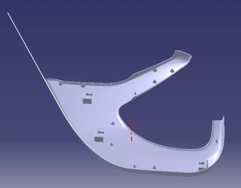
Boss on top of it. Next we have Lower Substrate, this is the Main part and every parts will be fixed on this part
so this wil not have any flanges but the Heat Stakes and the Dog Houses with the screw boss
on top of it. Next we make the Flanges with the same Boolean Operations, now, since this will be the
primay part which will join the LMP it needs to be HEAT STAKED so we have the heat stakes
on this part.
dog house
4. door arm rest
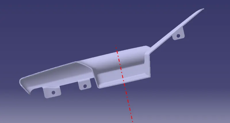
For the begnning, we have made the Arm Rest as a sing part, but after performing the draft
analysisi, we realized that it is not possible to make the part in one go, or it is, then will be
Costly. So we divided it into two parts as shwon in all the above images.
The final result with flanges,
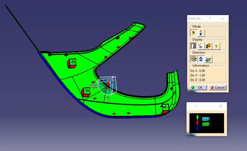
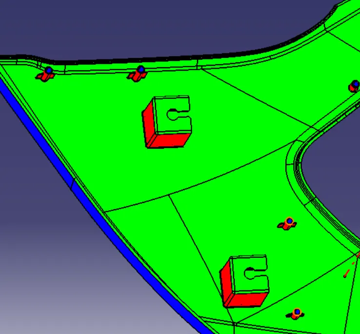
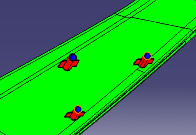
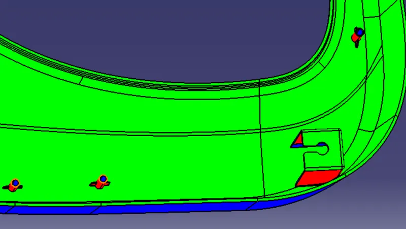
- draft analysis check
1. lower substate
2. bottle holder
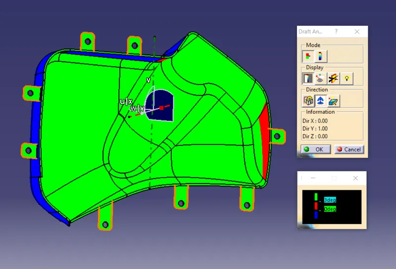
3. map pocket
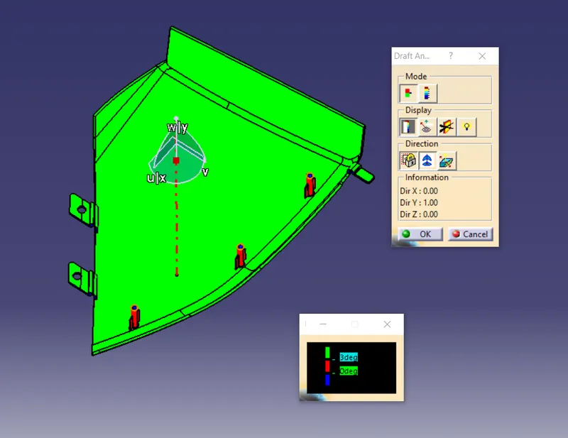
4. door arm rest
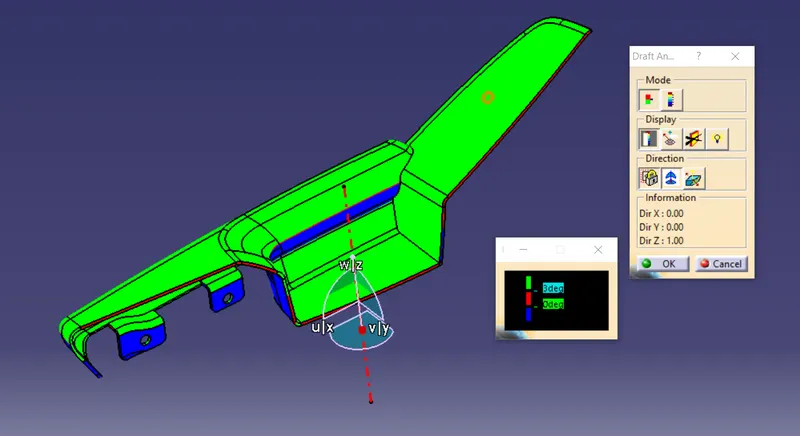
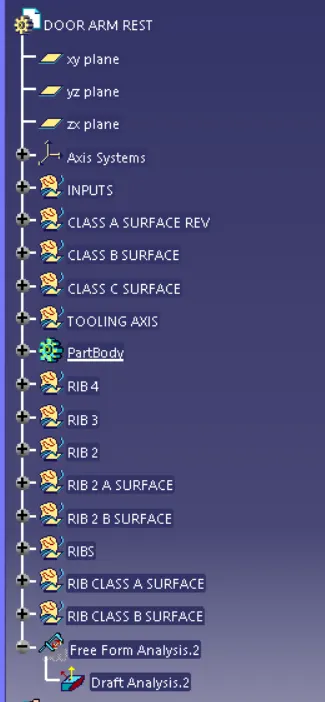
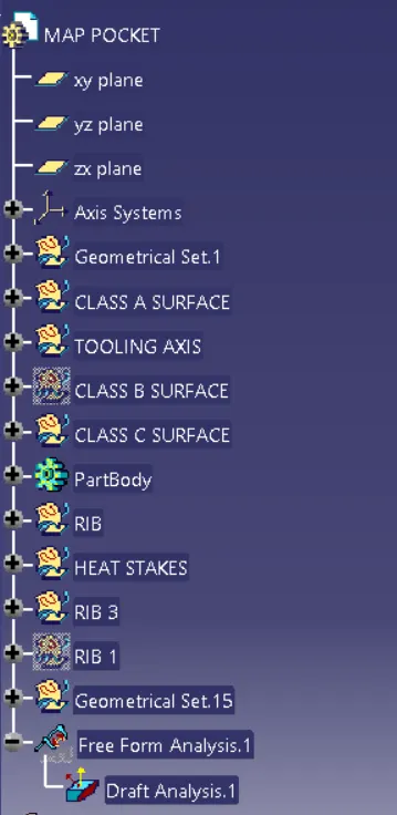
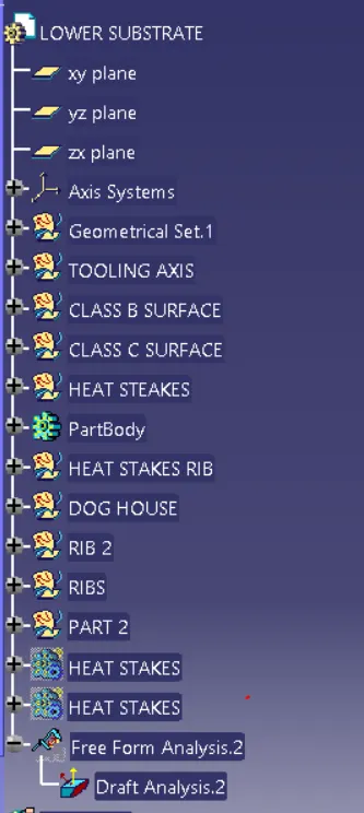
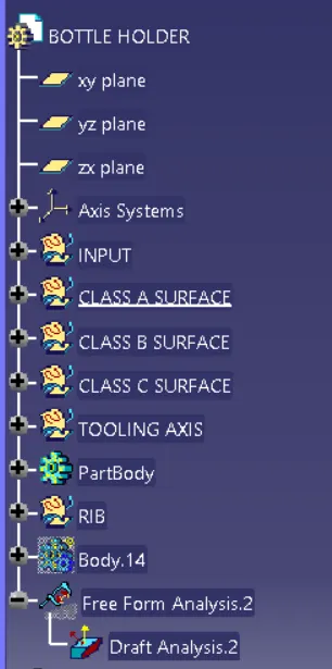
- deign tree
1. door arm rest
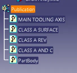
2. map pocket
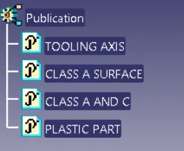
3. lower substate
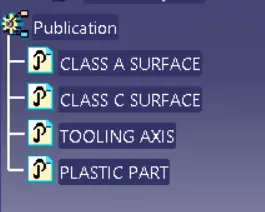
4. bottle holder
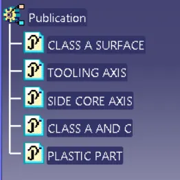
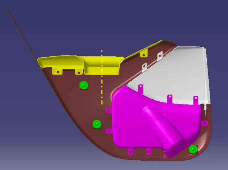
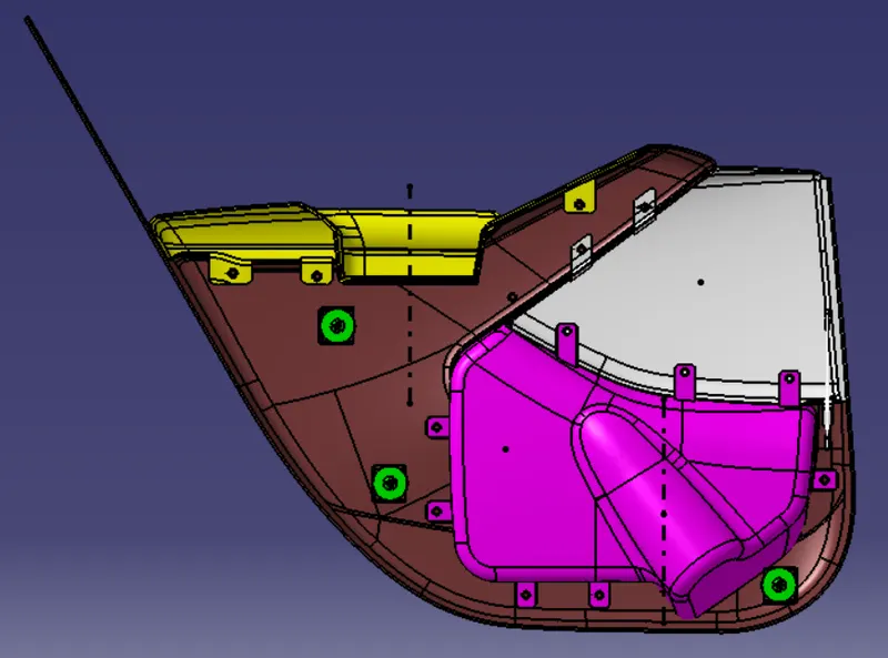
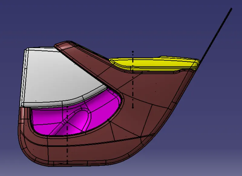
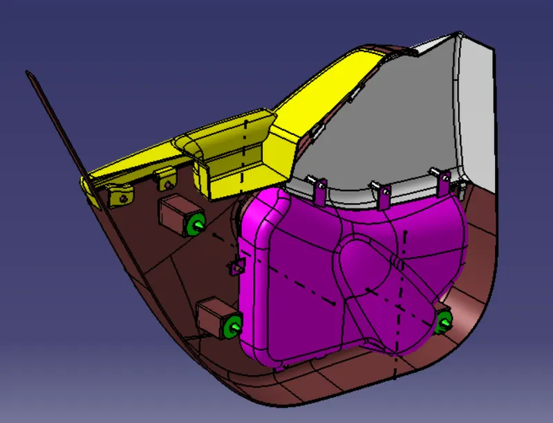
FINAL ASSEMBLY OF DOOR TRIMM PANEL
- assembly design tree