Week 11 - Final project
Development of a Door Trim panel
AIM :
To Create of CAD model considering following inputs as like in OEM and tier1 companies
- a) Class A surface
- b) Nominal thickness : Refer master sections
- c) Attachment strategy :
Find a attachment strategy for the door panel complete work.
Use Push pin with Dog house for Lower substrate – Door panel attachment
Use heat stakes for part to part attachment
PROCESS :
Master sections and class A were first provided from which we need to further work.
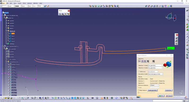
Thickness of the component was 2.5mm which was obtained from measuring master section.
The places where attachment features have to be created was studied next.
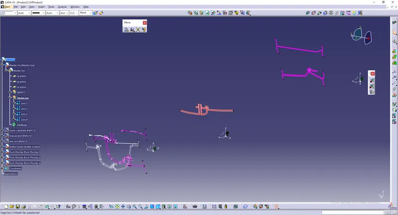
As we could see, the thickness is 2.5mm.
The class A surfaces of
1.arm rest
2.bottle holder
3.map pocket.
4.lower substrate.
Since the components are separate ones, we need to work on assemble work bench and fix them together at the last.
By clicking on part , we could work on part workbench or generative shape design.
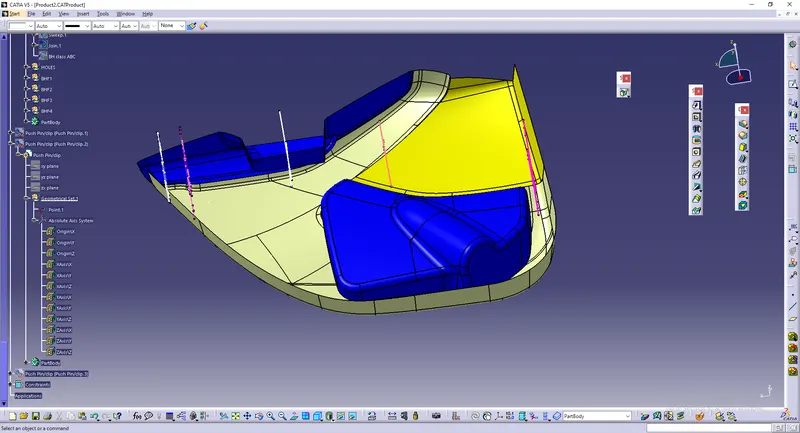
The given class A were indiviually studied whether all surfaces are joined together or not and also overlapping surfaces were checked.
As we could see in the image below , there is an overlapping surface in class A of arm rest.
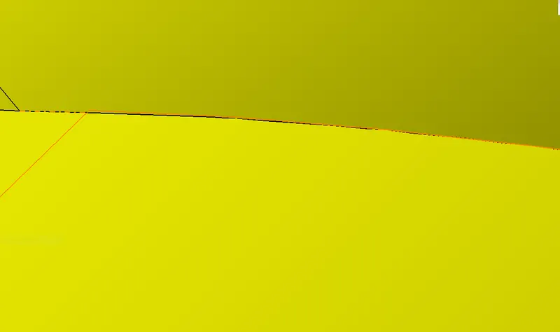
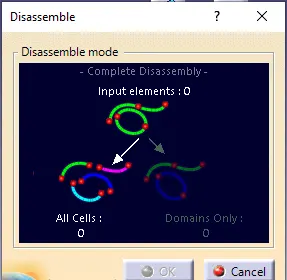
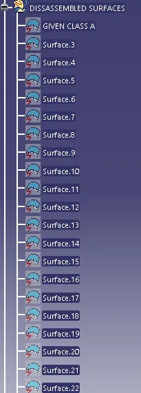
To rectify that we need to disassemble the elements.
Next we could use split option to remove the overlapping surface and the elements are again joined together using join option.
Creation of class B&C
Here lower substrate is considered first.
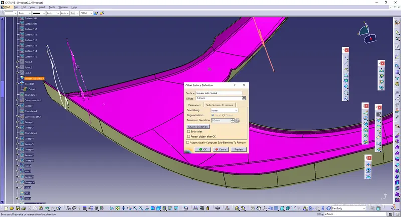
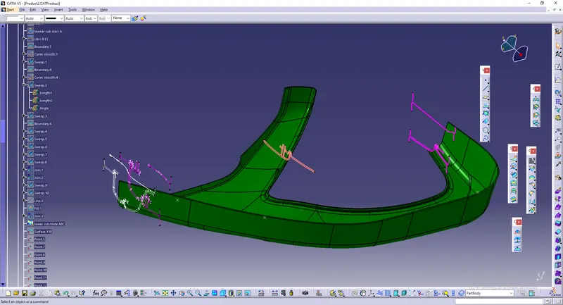
class B is created by taking offset from class A of about 2.5mm
Next for class C , we need to take out boundary or edges from class A.
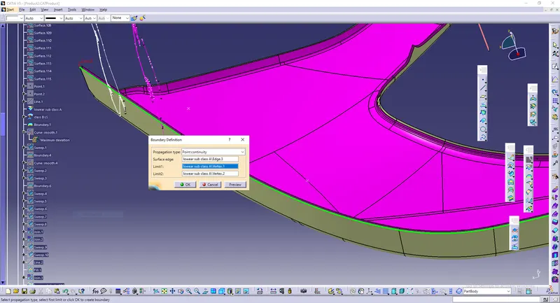
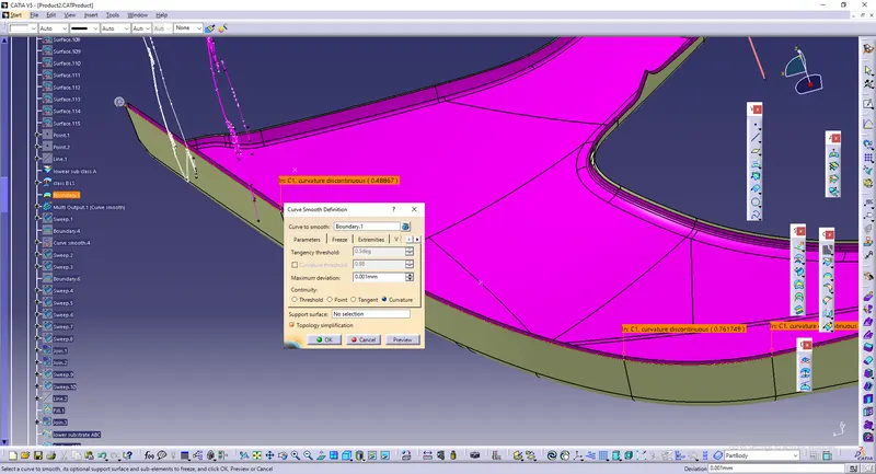
Smooth curve is given next.
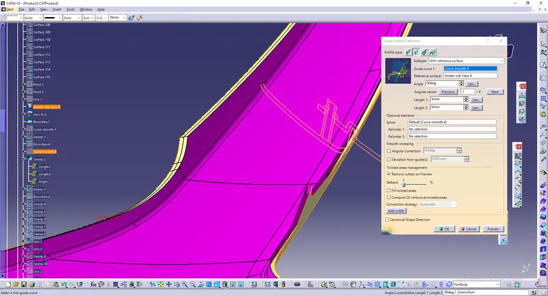
Sweep command is used to create class C.
Using with reference surface class C is made. The boundary shown in the above images acts as guide and reference surface is class A.
Make sure all three surfaces are intersection.
Join class A with C and trim it with class B like below.
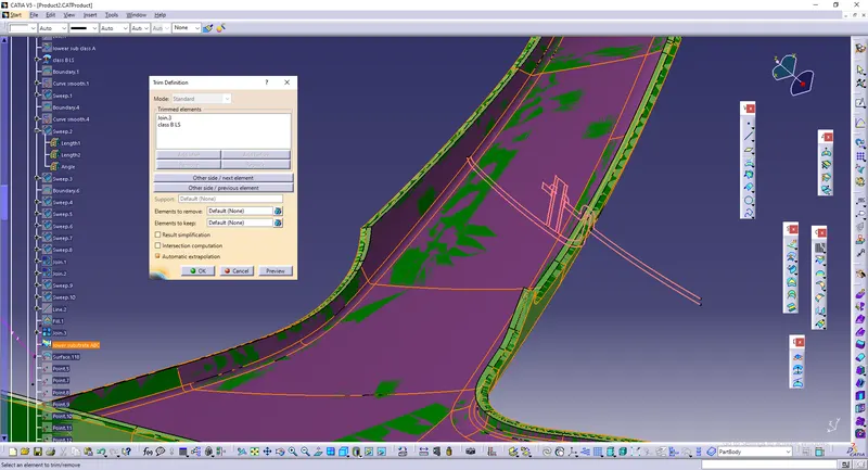
Overall class ABC for lower substrate.
Convert it into a solid by going to part workbench using option called closed body.
ATTACHMENT FEATURES IN LOWER SUBSTRATE.
DOG HOUSE :
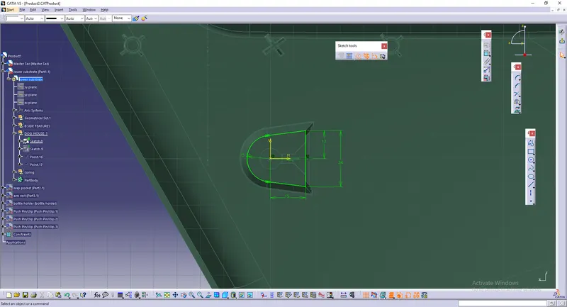
To create dog house, insert a point of height 30-35mm from bottom of lower substrate.
Next use that point as reference and draw profile for dog house in positioned sketch.
By going to part bench, convert it into 3D by pad option.
Make a profile like a key and cut that with the above solid.
Make a draft of 0.5 degrees.
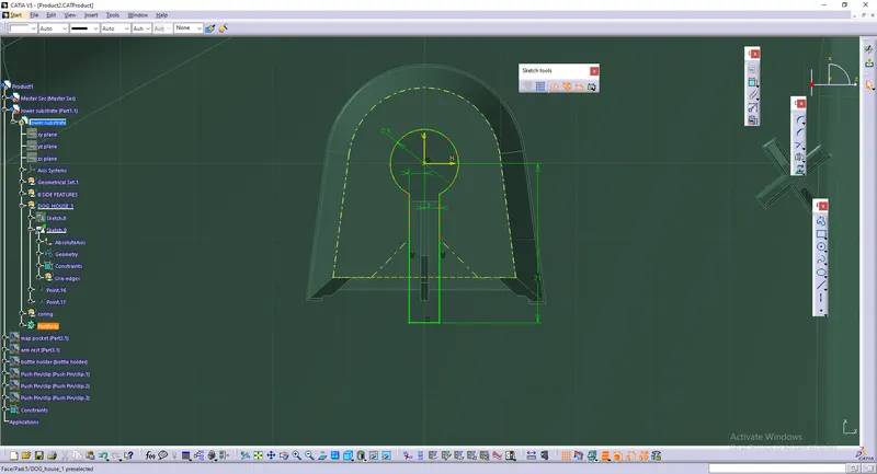
Next to make ribs, repeat the same. Ensure that the tip of the rib is of 2.5mm distance from top portion of dog house.

To provide coring , go to generative shape design .
Extract side and upper surface of dog house.
Make an offset of 1-1.5mm for side surfaces and top surface to a distance of 3-6mm from bottom portion of lower substrate.
Trim them together and use it as cutting elemnt.
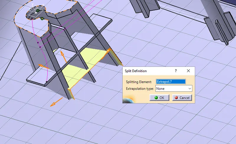
Again go to part bench and split it with dog house as shown below.
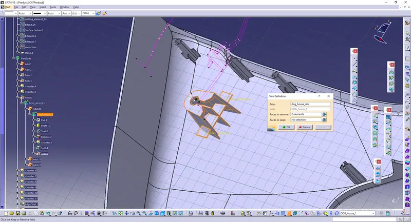
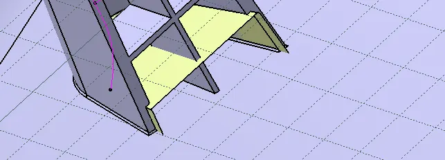
Splitting process :
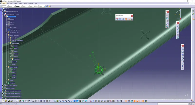
Heat stakes :
To create heat stakes, go to sketcher workbench and make two circles.
Pad the profile.
Next create ribs using same commands.
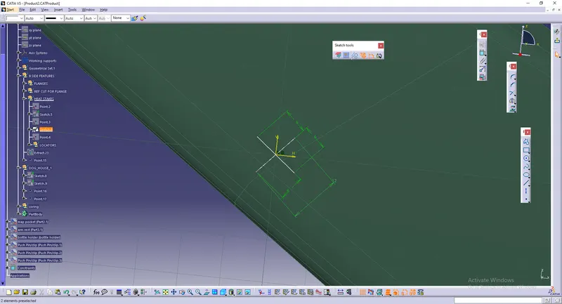
Locators :
Repeat the same for locators.
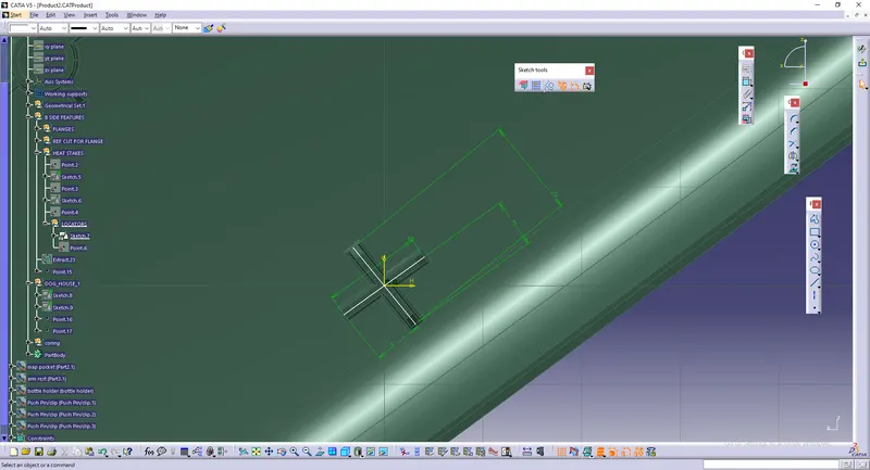
Make sure these features lie above flanges which we'll be creating next.
Flange Creation :
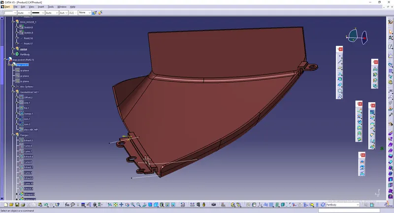
The image given below is a finished flange.
To create that we need to extrace the lines shown below from master section.
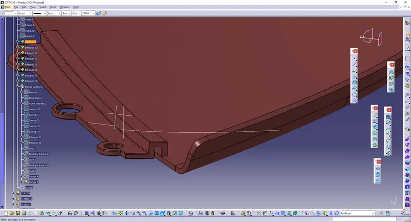
The extracted profile is swept to generate surfaces which is shown below.
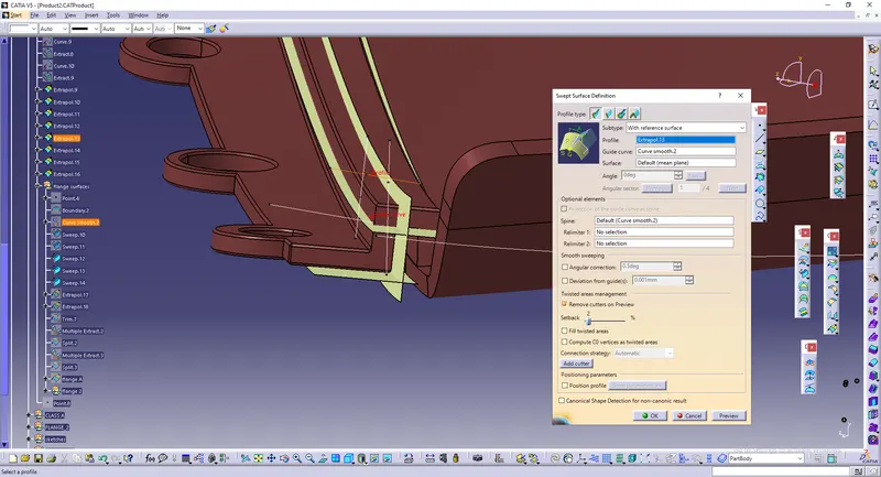
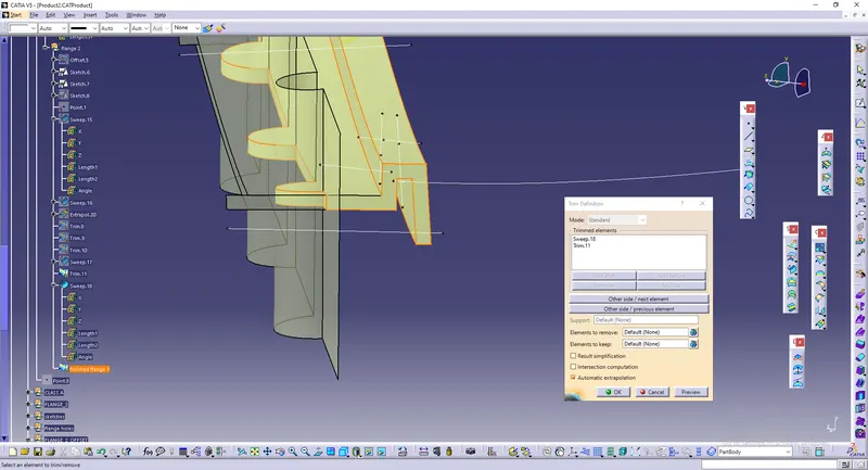
Trim them together to get class A of flange like shown below.
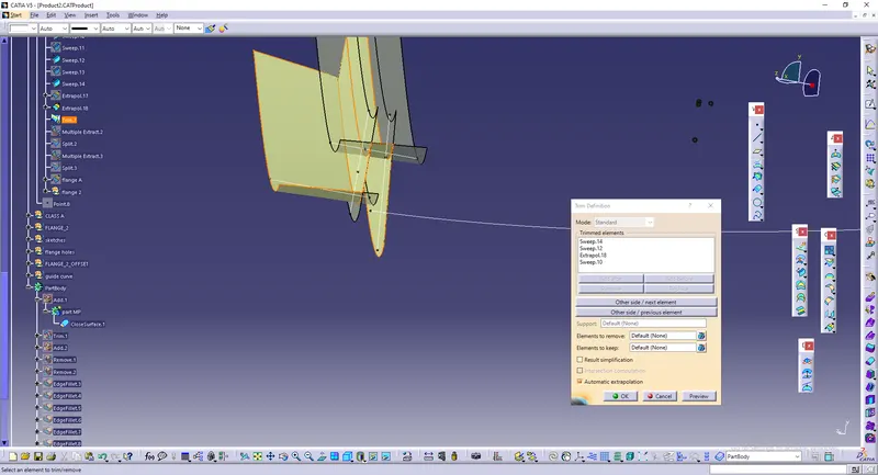
Offset the class A to 2.5mm to create class B for flange.
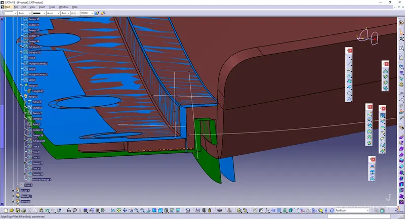
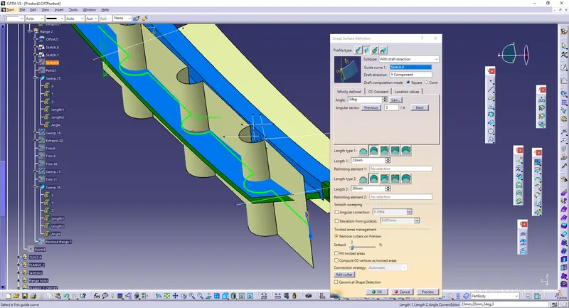
The front portion of flange is made like given below.
It is done in sketcher workbench.

Exit sketch workbench and go back to surface.
Sweep it with proper draft which will be class C
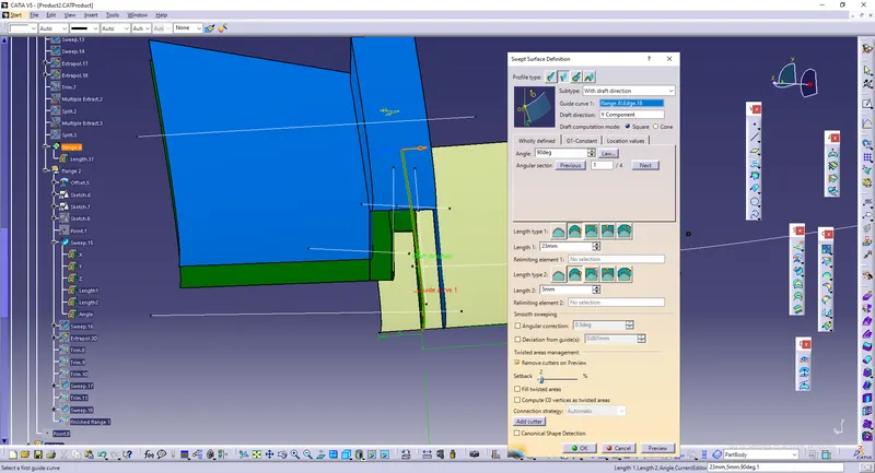
Trim them together to get a flange for map pocket.
CLASS ABC with FLANGES :
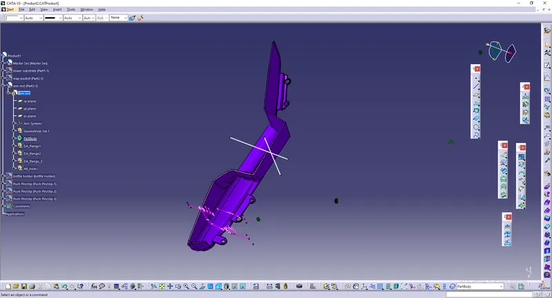
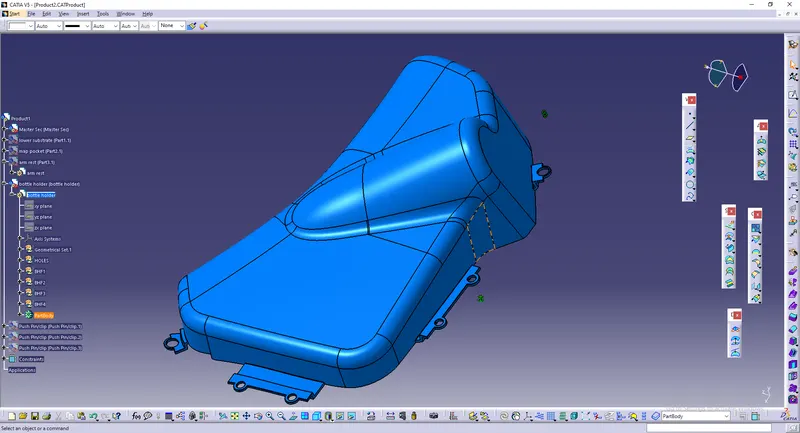
Repeat the same process for other components also for creating class ABC and flanges.
ASSEMBLY :
Next click on existing component and insert pushpin which has to be assembled with dog house.
Import the pushpin component.

Use manipulation to move the component near dog house.
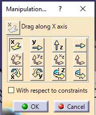
Next select bottom portion of push pin and top portion of dog house to coincide.
Also select the points of both components to coincide.
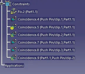
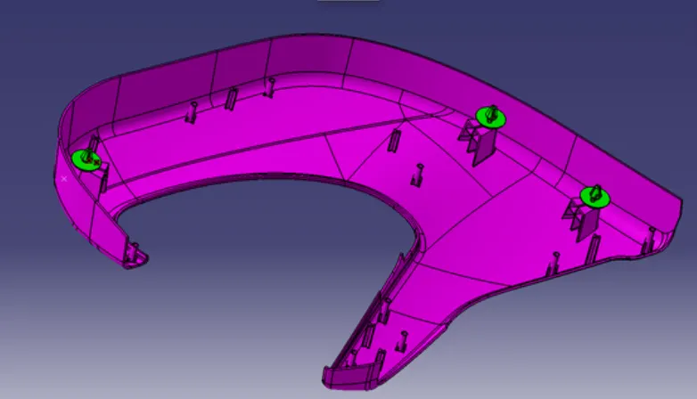
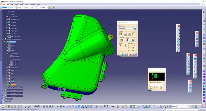
DRAFT ANALYSIS :
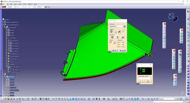
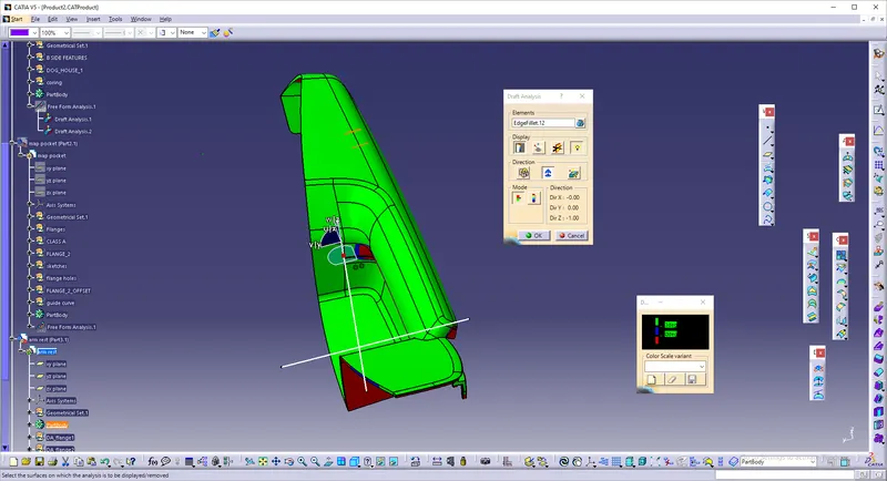
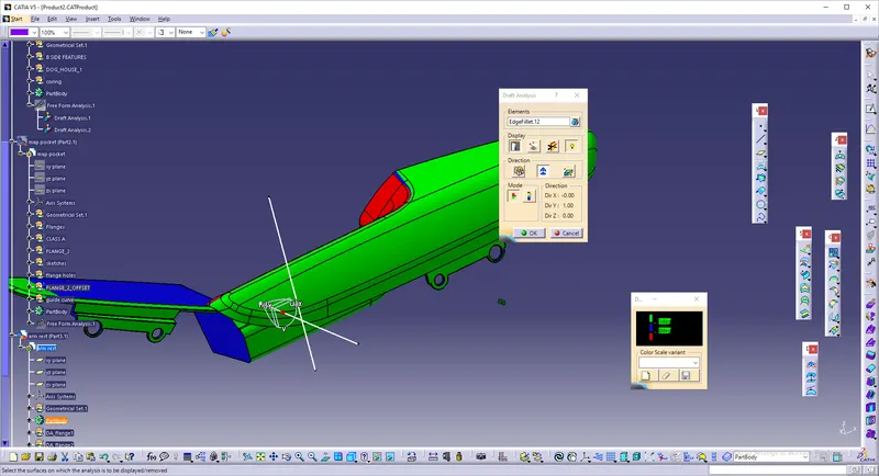
Next draft analysis has to be done.
Draft is nothing but the angle or taper available in surfaces of a part.
As we did earlier ,especially while creating class C surfaces or giving draft to features in part workbench, now we need to check whether those angles given fall under criteria or not.
Draft for main component is 3 degrees and for atachment features is 0.5 degrees.
Draft analysis is attached below for separate components and attachment features.
Consider proper tooling axis before executing draft analysis.
Lower substrate :
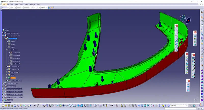
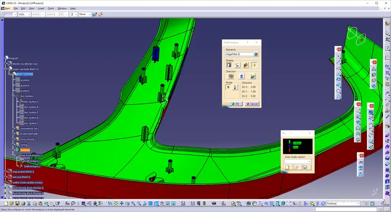
Map pocket :
Arm rest :
Bottle holder :