Week 11 - Final project
Aim : To create CAD model considering following inputs as like in OEM and tier1 companies
- Class A surface
- Nominal thickness : Refer master sections
- Attachment strategy :
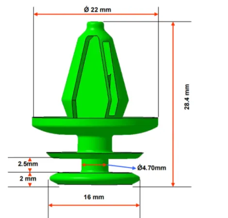
Use Push pin with Dog house for Lower substrate – Door panel attachment
Use heat stakes for part to part attachment
Abstract : The project deals with explanation of steps and procedures followed while developing the door trim panel of a car using catia v5 using the class a surface. I was able to create the tooling axis, class B surface, class C surface and after forming the solid body form that I was able to create the flanges and the b-side features such as Dog House, push pins, heat stakes, etc and finally the draught analysis is also done on the components to check the manufacturability of the component.
Door Panel : Automotive door panel is a vital component in a vehicle as it allows entry/exit access to the vehicle. Apart from this primary function, door panels are also responsible for the protection of the driver as well as the passengers present inside the vehicle. Moreover, door panels also give a stylish look to the vehicle, as they have the ability to integrate various interior parts, which are mounted on door trim. Such door panels differ from one manufacturer to another and from car model to model. Further, door panels are considered as one of the crucial components in vehicles as they provide reliable side protection, ergonomic comfort, and convenience coupled with attractive and soft-touch surfaces. They are usually made up of steel, aluminum, or mixed material.

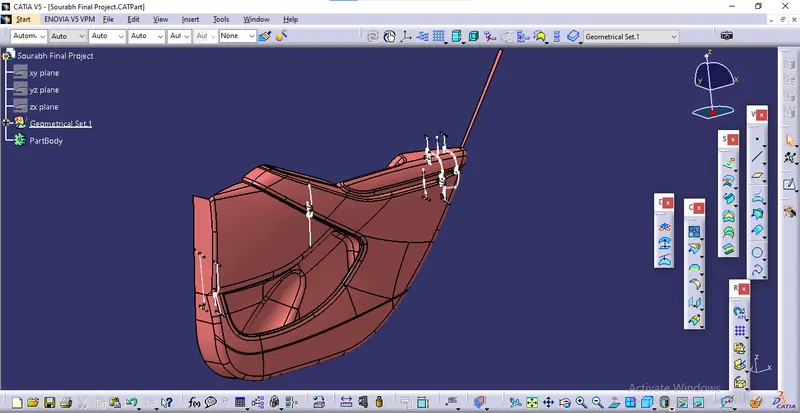
Given Master Section Development file
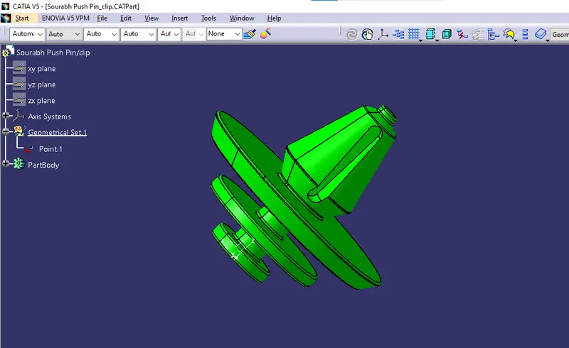
Push Pin
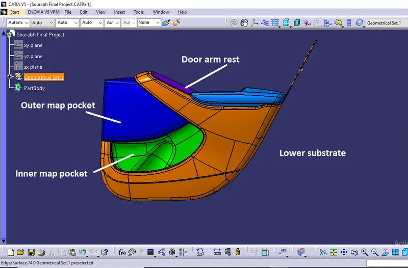
Now we will divide the given surfaces into four parts to prepare each part individually for manufacturing and then for assembly
1. Lower Substrate
Class A Surface : In automotive design, a class A surface is any of a set of freeform surfaces of high efficiency and quality. Although, strictly, it is nothing more than saying the surfaces have curvature and tangency alignment – to ideal aesthetical reflection quality, many people interpret class A surfaces to have G2 (or even G3) curvature continuity to one another.
Steps
- Create a point on the class A surface to move the main tool for component creation.
- Make an axis over the point created with the same direction as the main axis.
- Using intersect command select the y z plane as first element and the class a surface as second element and tooling axis is created.
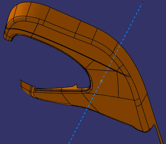
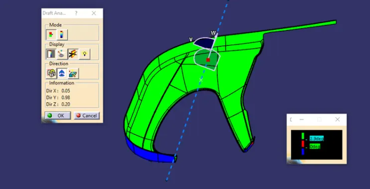
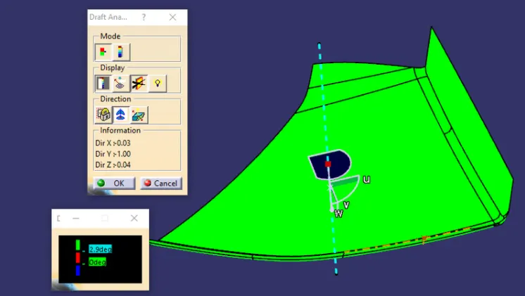
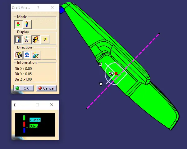
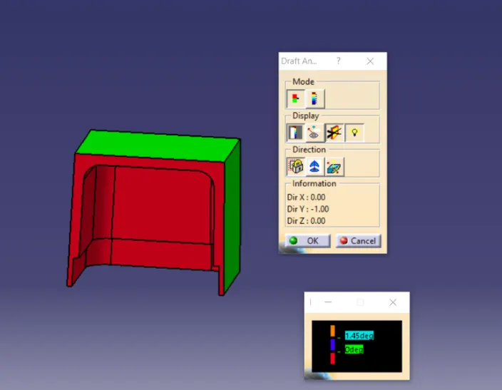
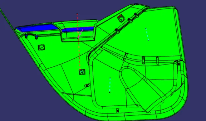
Draft Analysis : The Draft Analysis command enables you to detect if the part you drafted will be easily removed. This type of analysis is performed based on color ranges identifying zones on the analyzed element where the deviation from the draft direction at any point, corresponds to specified values.
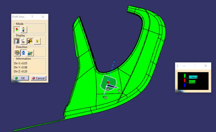
Class B Surface
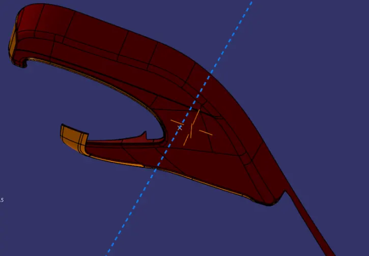
Class C Surface
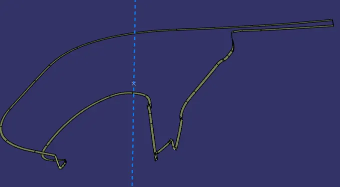
Final Trim
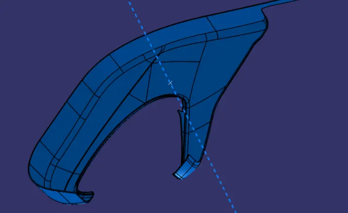
Draft Analysis after the final trim
2. Outer Map Pocket
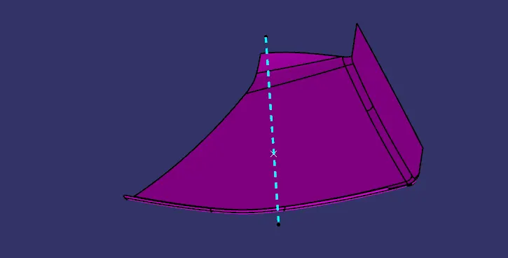
Class A Surface
Draft Analysis of Class A
Class B Surface
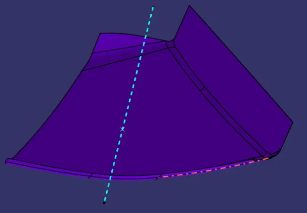
Class C Surface
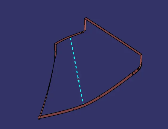
Final Trim
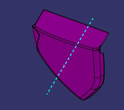
Draft Analysis :
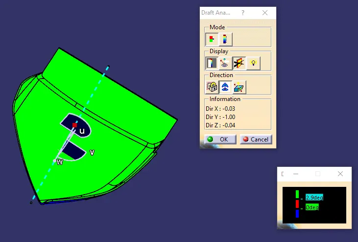
3. Door Armrest :
Class A Surface
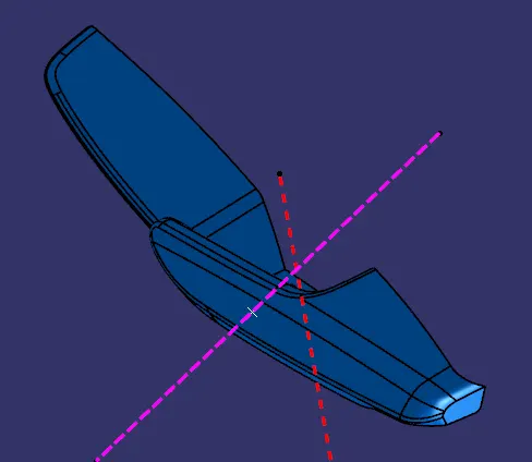
Draft Analysis
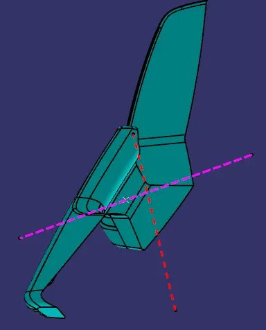
Class B Surface
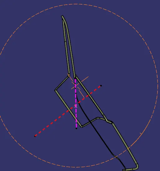
Class C Surface
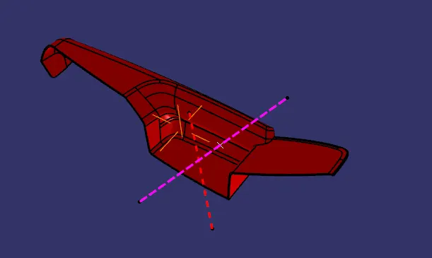
Final Trim
Draft Analysis
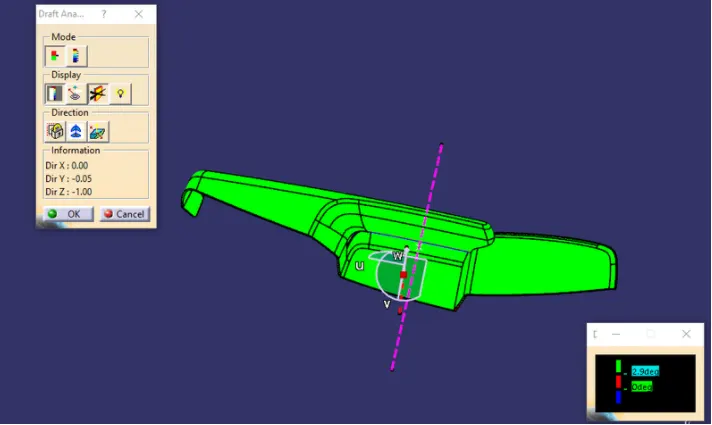
4. Inner Map Pocket :
Class A Surface
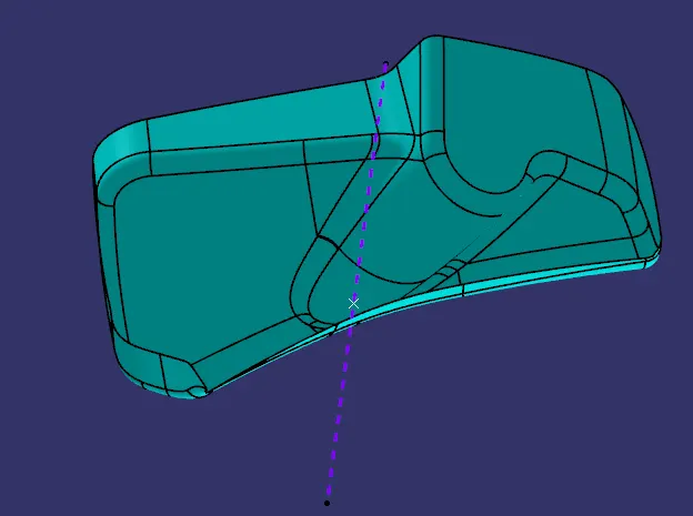
Draft Analysis
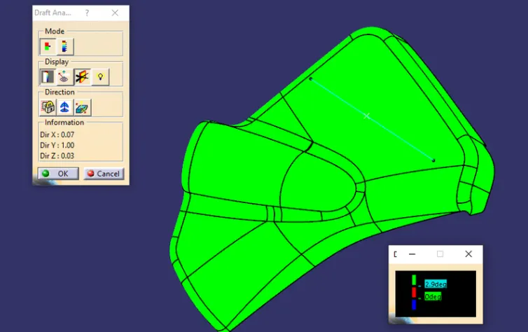
Class B Surface
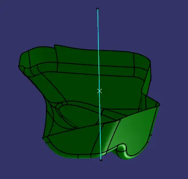
Class C Surface
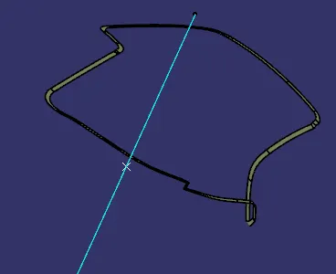
Final Trim
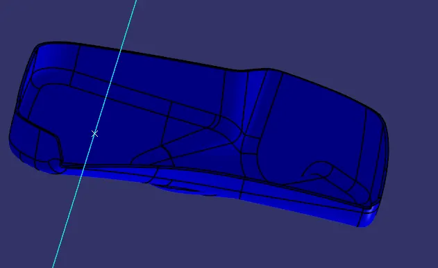
Draft Analysis
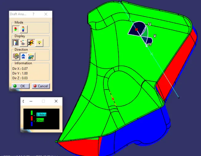
Flanges :
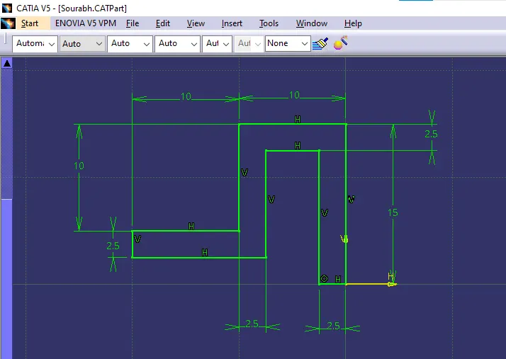
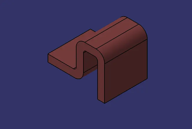
A flange is a protruded ridge, lip or rim, either external or internal, that serves to increase strength; for easy attachment/transfer of contact force with another object or for stabilizing and guiding the movements of a machine or its parts. The term "flange" is also used for a kind of tool used to form flanges.
Sketch :
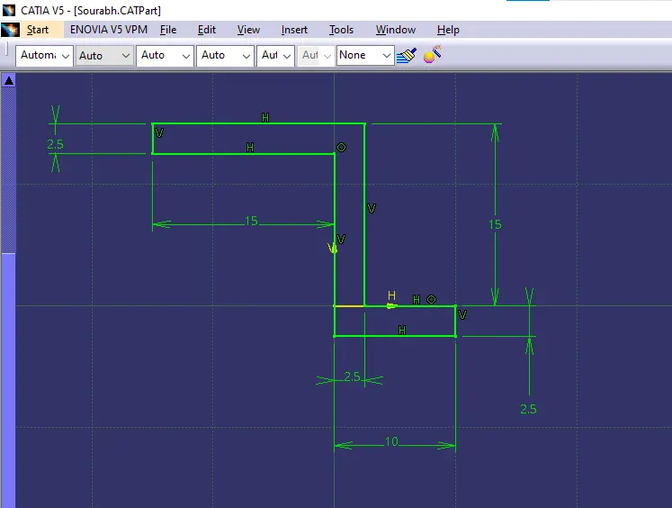
Part Body :
Dog House :
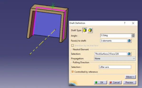
Dog house is an engineering feature used in plastic trim design. Dog houses are used as supporting feature. Sometimes other engineering features like snaps; locators etc. are mounded on them to increase their strength. Dog houses are subjected to draft analysis to prevent breakage of the component during ejection from mould cavity. Dog house and other engineering components are built on B-surface.
Push Pin :
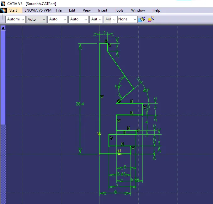
Sketch
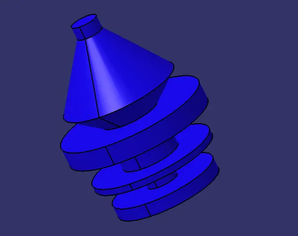
Part Body :
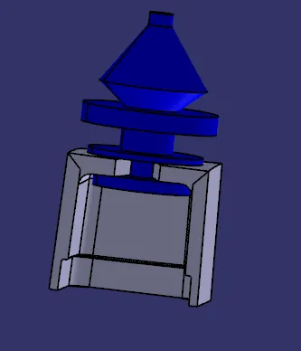
Push pin along with dog house :
Now by using Pad definition I extracted the circles upto 7mm above flange and rest below upto main body.
HeatStakes :
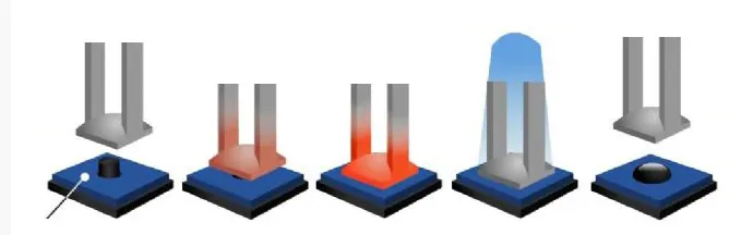
Heat Staking is a pulsed-heat process to join two or more parts out of which one at least is made of plastic. The process is to deform the plastic material using heat and force at a set process time. The bond is made by partially de-forming the plastic part in order to fix the other.
- The 3-2-1 principle states that the six locators are sufficient to restrict the required degree of freedom of any workpiece. In this, motion is restricted using clamps and locators. A three-pin base can restrict five motions and six pins restrict nine motions.
Lower Substrate :
[1] The workpiece is resting on three pins A, B, and C which are inserted in the base of the fixed body.
[2] The workpiece cannot rotate about the axes XX and YY and also cannot move downward.
[3] In this way, the five degrees of freedom 1,2,3,4 and 5 have been arrested.
[4] Two pins D and E are inserted in the fixed body, in a plane perpendicular to the plane containing pins A, B & C.
[5] Now the workpiece cannot rotate about the Z-axis and also it cannot move towards the left.
[6] Hence the addition of pins D and E restrict three more degrees of freedom, namely 6, 7, and 8.
[7] Another pin F in the second vertical face of the fixed body, arrests degree of freedom 9.
The above method of locating a workpiece in a fixture is called the 3-2-1 Principle.
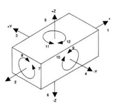
A workpiece will be completely confined when blanked against:
- 3 points in one plane: The “3” in 3-2-1 refers to 3 locators (passive fixture elements) on the primary locating/datum surface.
- 2 points in another plane: The “2” in 3-2-1 refers to 2 locators on the secondary locating/datum surface.
- 1 point in a third plane: The “1” in 3-2-1 refers to 1 locator on the tertiary locating/datum surface.
Final Body :
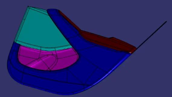
Smooth edged body
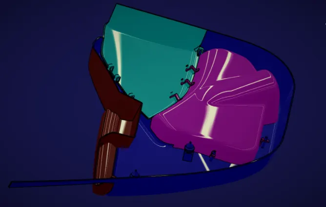
Draft Analysis of the body
Conclusion :
This concludes the creation of the door trim panel along with engineering features using the given Class A mastersection.