Photo Realistic Rendering
Title : Modelling and Assembly of an American Chopper
Objectives :
The main objectives of this project are
- To design the parts of the Chopper.
- To create an assembly of a Chopper.
- To know the application of the decals and photoview 360.
Introduction :
Solidworks is ‘the software to master’ which helps us to design and make simulation of the mechanical products which convert the 2D sketch in a Three Dimensional model which helps to understand the visual realisation of the part to be converted in real time and it has many add in features like photo view 360 which helps in rendering of the final model to make it picture realistic.
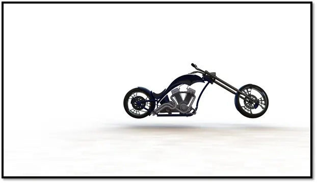
This report gives the detailed modelling and assembly of an American Chopper.
Methodology :
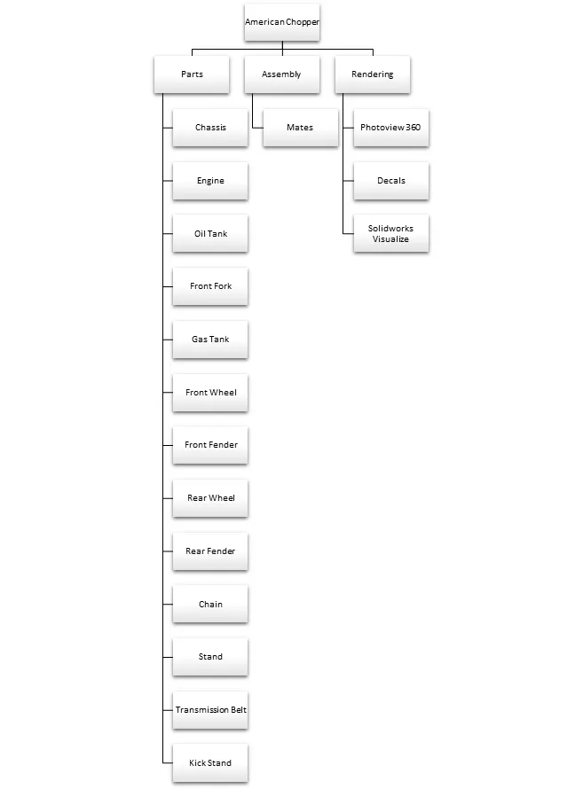
American Chopper Parts :
1) Chassis :
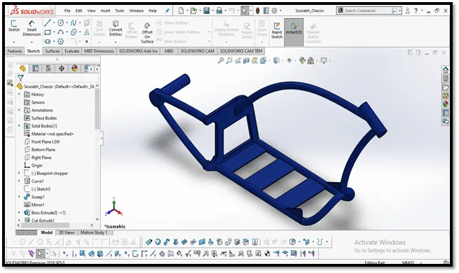
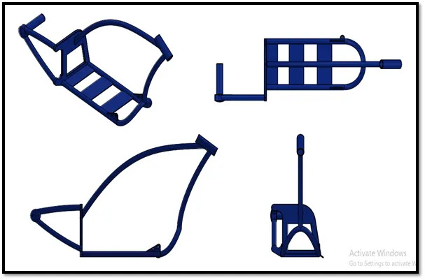
The chassis is considered to be one of the significant structures of an automobile. It is the frame which holds both the car body and the power train. Various mechanical parts like the engine and the drive train, the axle assemblies including the wheels, the suspension parts, the brakes, the steering components are bolted onto the chassis. The chassis provides the strength needed for supporting the different vehicular components as well as the payload and helps to keep the automobile rigid and stiff.
Description :
- Make a new part and name it as Chassis.
- Make a sketch on the top plane and form a projected curve.
- Create a surface sweep and mirror the sweep.
- Make a sketch on the side plane and extrude it.
- Perform extrude curve on the surface.
- Apply fillet and chamfer.
- Make both the sweeps at the rear of the chassis.
- Make two sweeps on the front plane.
- Use Combine feature.
- Extrude and merge the base plates to hold the engine.
2) Engine :
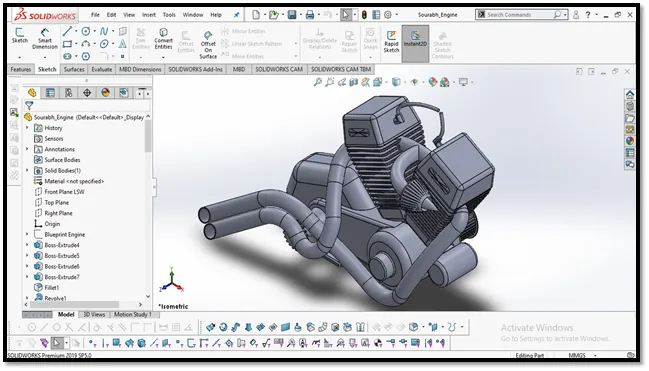
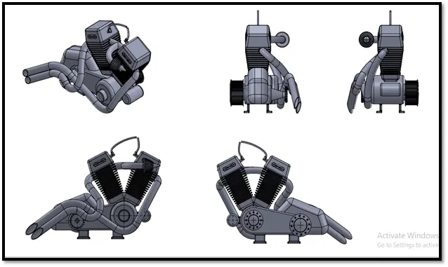
An engine is a machine that converts energy from a fuel to some mechanical energy, creating motion in the process. Engines - such as the ones used to run vehicles - can run on a variety of different fuels, most notably gasoline and diesel in the case of cars. However, there do exist some alternative fuel types such as biofuels and natural gas. In thermodynamic terms, engines are generally referred to as heat engines, which produce macroscopic motion from heat. The heat in this case comes from the combustion of fuel in the engine, which moves pistons.
Here we are using a Two Cylinder Four Stroke Engine.
Description :
- Make a new part and name it as Engine.
- Open the blueprint of the engine.
- Make a sketch on the front plane.
- Extrude the sketches and apply fillet.
- Make a sketch on the extruded surface and then revolve it, that will be the transmission belt pulley.
- Make a dome at the end.
- Cut extrude the holes on the dome using circular pattern making 12 instances of it on both the sides.
- Make the sketch on the top plane and extrude it to form the piston-cylinder housing
- Mirror the housing.
- Sketch the stands on the bottom surface and extrude them.
- Project the two curves from the sketch and sweep them.
- Use split feature at the end of the sweep.
3) Transmission Belt :
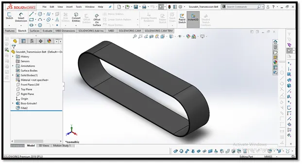
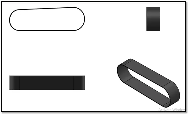
The main purpose of transmission belt is to transmit power which is developed inside the engine to gear box with maximum efficiency.
Description :
- Make a new part and name it as Transmission Belt.
- Sketch the belt on the front plane and extrude it.
- Apply fillet.
4) Chain :
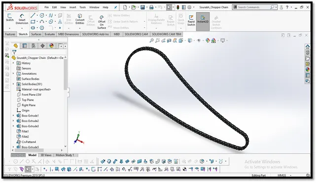
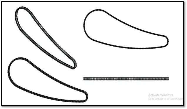
The chain connects the output shaft of the transmission to the rear wheel. It makes the rear wheel turn, which moves the motorcycle.
Description :
- Make a new part and name it as Chain.
- Make a sketch on the front plane and extrude it.
- Apply fillet.
- Use curve driven pattern.
- Mirror the chain plates.
5) Gas Tank :
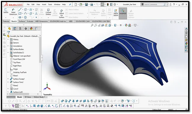
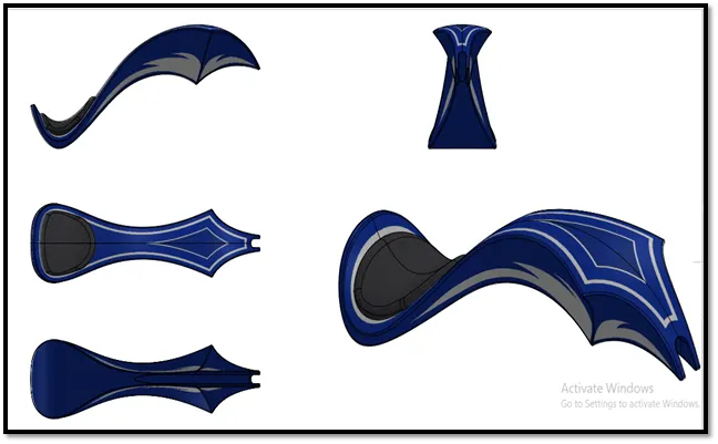
A Gas tank is a safe container for flammable fluids. Though any storage tank for fuel may be so called, the term is typically applied to part of an engine system in which the fuel is stored and propelled (fuel pump) or released (pressurized gas) into an engine.
Description :
- Make a new part and name it as Gas tank.
- Create a sketch on mid plane using spline and line entities.
- Make a surface sweep and trim the excess surface.
- Make a projected curve using the sketches.
- Make another surface sweep and the second curve.
- Use the boundary surface option and mirror the tank.
- Knit the surfaces and merge them.
- Perform a cut sweep.
- Fillet the edges.
6) Front Fork :
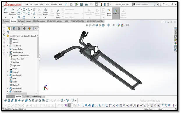
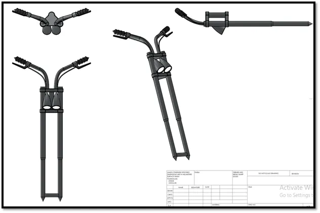
A motorcycle fork connects a motorcycle’s front wheel and axle to its frame, typically via a yoke, also known as a triple clamp, which consists of an upper yoke joined to a lower yoke via a steering stem, a shaft that runs through the steering head, creating the steering axis.
Description :
- Make a sketch on the front plane and revolve it around the axis.
- Extrude a solid body at the end of the rod and use linear pattern for making 2 instances of the solid body.
- Make the headlight.
- Use sweep to make the handle bars.
- Make a projected curve for the wires.
- Mirror the part and then combine the front fork.
7) Kick Stand :
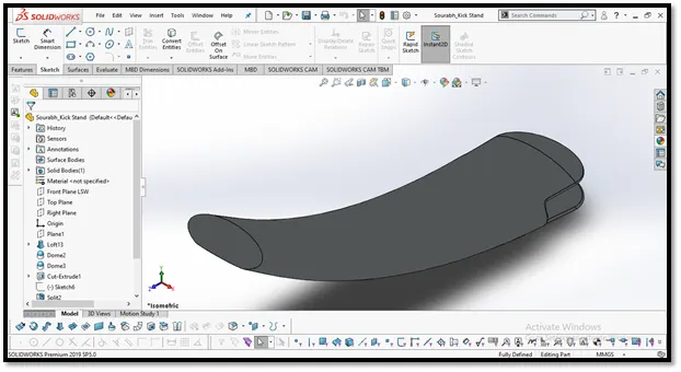
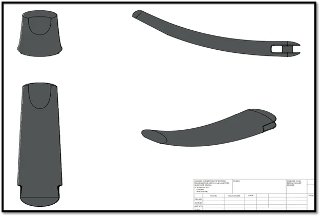
A kickstand is usually a piece of metal that flips down from the frame and makes contact with the ground. It is generally located in the middle of the bike or towards the rear. Some touring bicycles have two: one at the rear, and a second in the front.
Demonstrate :
- Make a new part and name it as Kick Stand.
- Create a loft using an ellipse and a spline.
- Make dome at both the ends.
- Extrude cut the bottom edge of the stand.
8) Front Wheel :
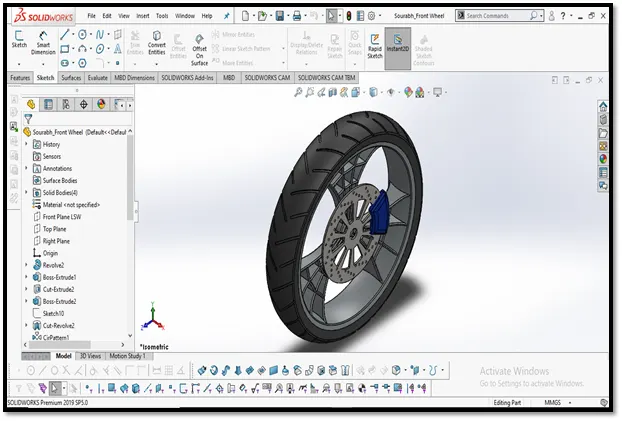
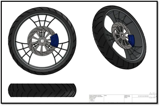
A solid disk or a rigid circular ring connected by spokes to a hub, designed to turn around an axlepassed through the centre. In its primitive form, a wheel is a circular block of a hard and durable material at whose centre has been bored a hole through which is placed an axle bearing about which the wheel rotates when torque is applied to the wheel about its axis.
Description :
- Make a sketch on the front plane and revolve it around the axis.
- Make a sketch using spline and extrude the spoke.
- Apply circular pattern and make 3 instances of the spokes.
- Apply combine feature.
- Apply fillet.
- Make rotor and calliper and chamfer them.
- Make a sketch on the front plane and then use revolve to make a tyre.
- Use circular pattern to make the sipes on the tyre.
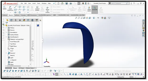
9) Front Fender :

10) Rear Wheel :
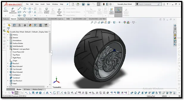
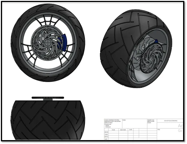
A solid disk or a rigid circular ring connected by spokes to a hub, designed to turn around an axlepassed through the centre. In its primitive form, a wheel is a circular block of a hard and durable material at whose centre has been bored a hole through which is placed an axle bearing about which the wheel rotates when torque is applied to the wheel about its axis.
Description :
- Make a sketch on the front plane and revolve it around the axis.
- Make a sketch using spline and extrude the spoke.
- Apply circular pattern and make 3 instances of the spokes.
- Apply combine feature.
- Apply fillet.
- Make rotor and calliper and chamfer them.
- Make a sketch on the front plane and then use revolve to make a tyre.
- Use circular pattern to make the sipes on the tyre.
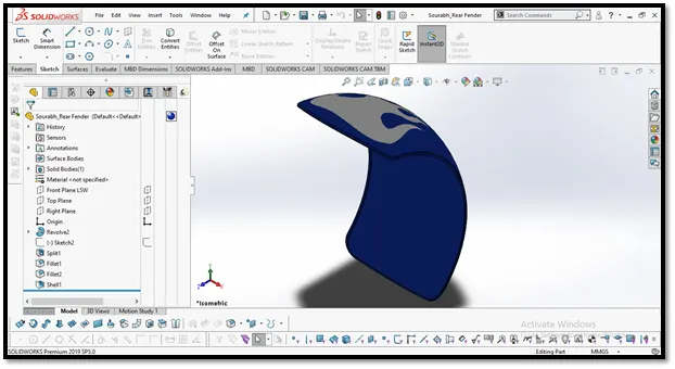
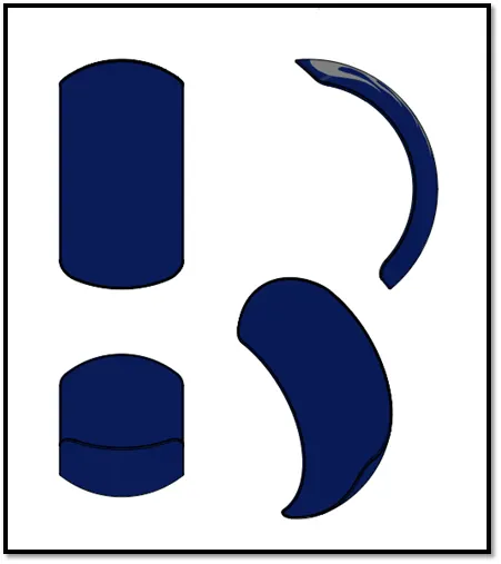
11) Rear Fender :
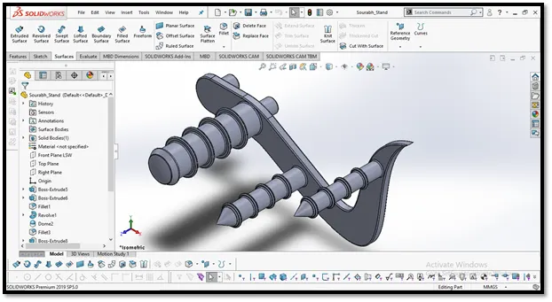
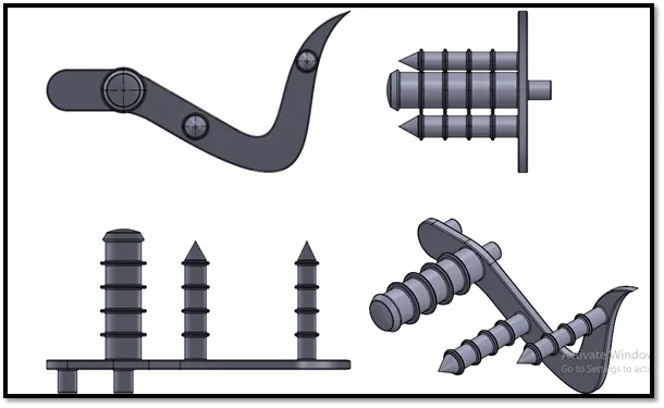
12) Stand :
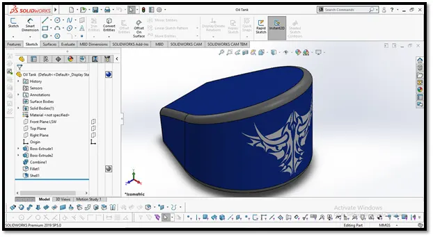
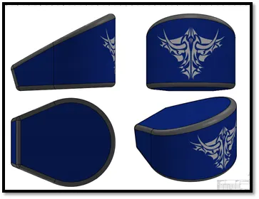
13) Oil Tank :
14) Assembly :
Description :
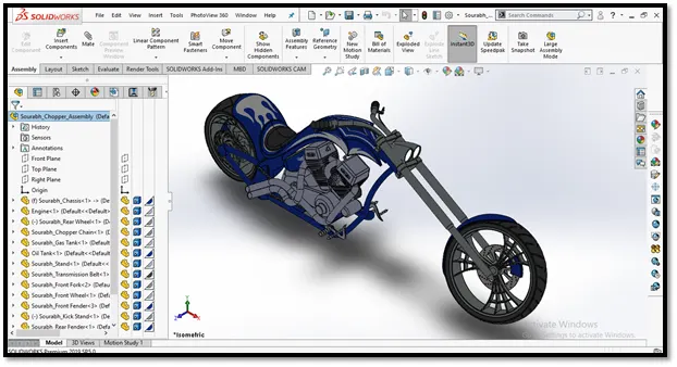
- Create an assembly file.
- Insert all the components in the workspace.
- Mate all the components properly.
- The final assembly is ready.
Rendering :
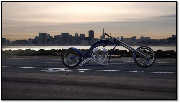
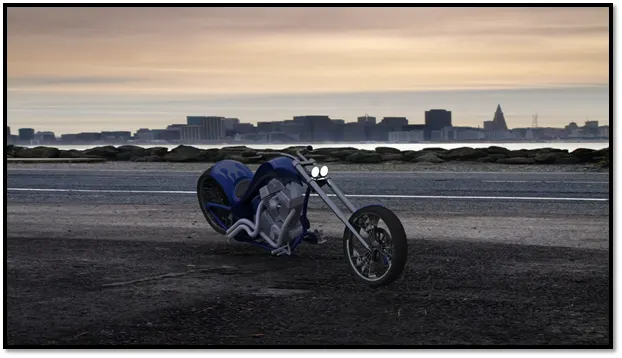
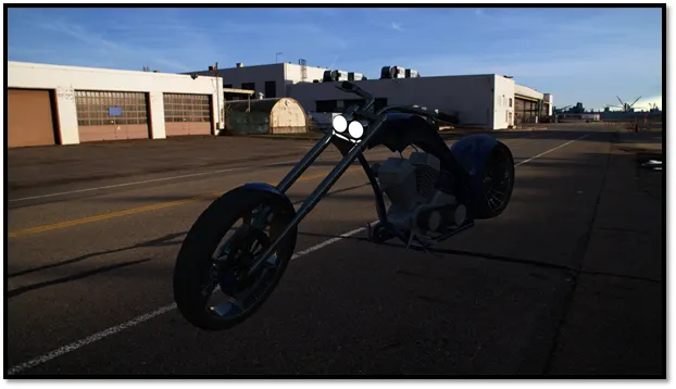
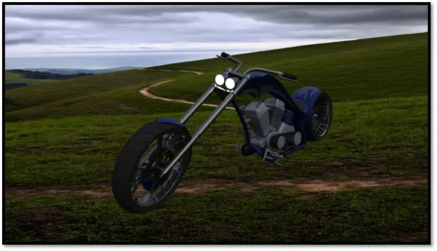
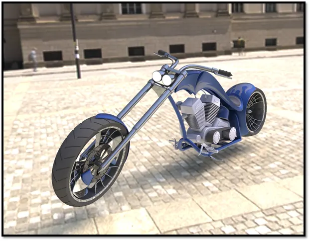
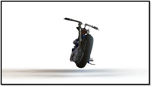
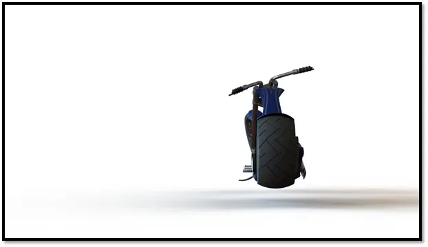
PhotoView 360 is a SOLIDWORKS add-in that produces photo-realistic renderings of SOLIDWORKS models. The rendered image incorporates the appearances, lighting, scene, and decals included with the mode.
Photoview 360 :
Photo View 360 is a visualization and rendering solution included with solidworks professional and solidwork premium. Providing a highly interactive environment for viewing designs as well as for creating photo-realistic renderings that can be used to show your designs.
Conclusion :
- Solidworksassists BluEntCAD professionals to generate the most intelligent solutions when it comes to designs.
- It is the handiest software to design the product.
- Solidworks help understand the design process easily because of its graphics which is a helpful tool.