Week 8 - Challenge 2 - Base Bracket Design
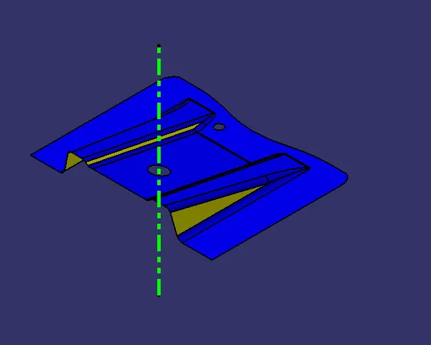
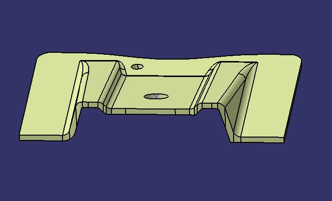
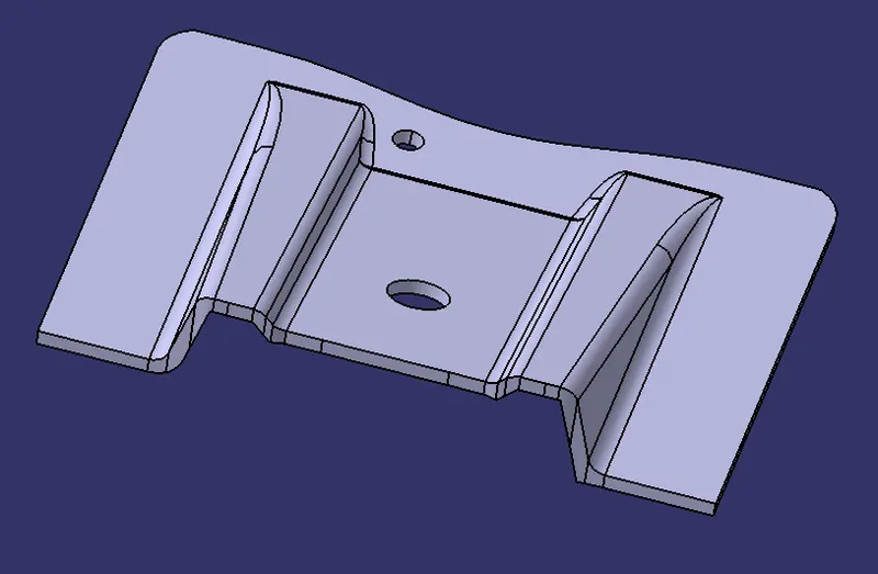
Aim : To create the Base Bracket Plastic component through the given Class-A surface.
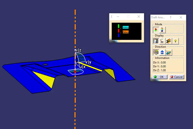
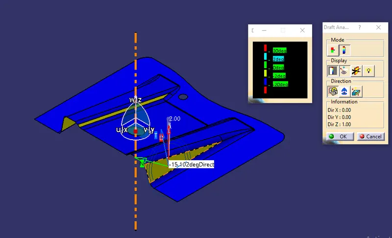
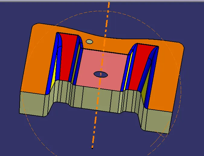
Draft Analysis : It helps you to detect if the part you drafted will be easily removed. This type of analysis is performed based on color ranges identifying zones on the analyzed element where the deviation from the draft direction at any point, corresponds to specified values.
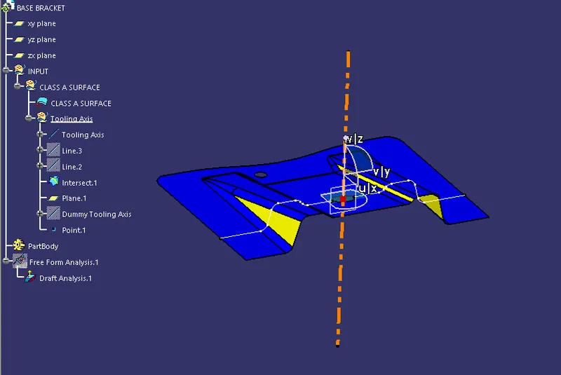
Tool axis : It is used to Select and define the tool orientation. The default value is Vertical, which is used for standard 3-axis machining. However, it can also be a fixed angle or a continuously changing orientation.
Procedure :
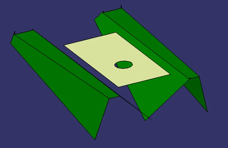
Step 1 : Import the given file in Catia Software.
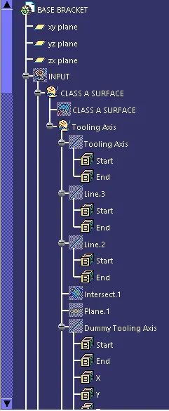
Step 2 : Add a dummy tooling Axis
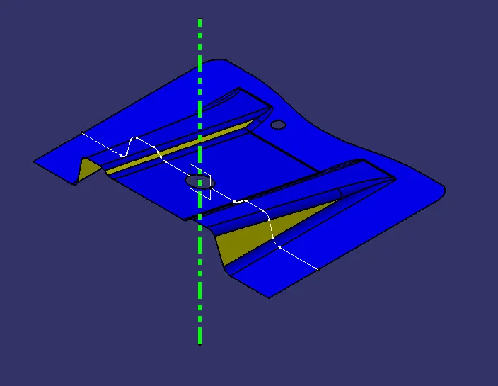
Step 3 : Add a reference yz plane.
Step 4 : Use intersect feature at reference plane yz
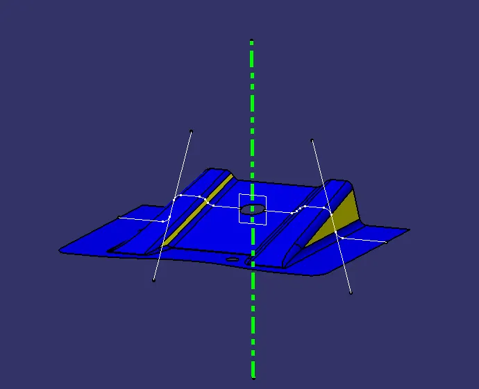
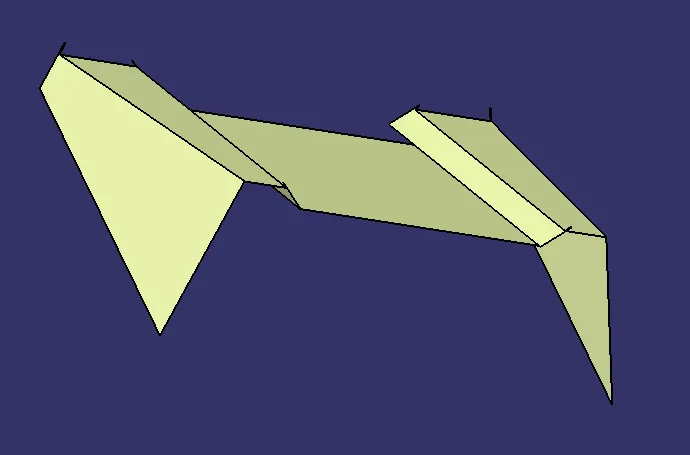
Step 5 : Add lines on both the sides using point to point direction
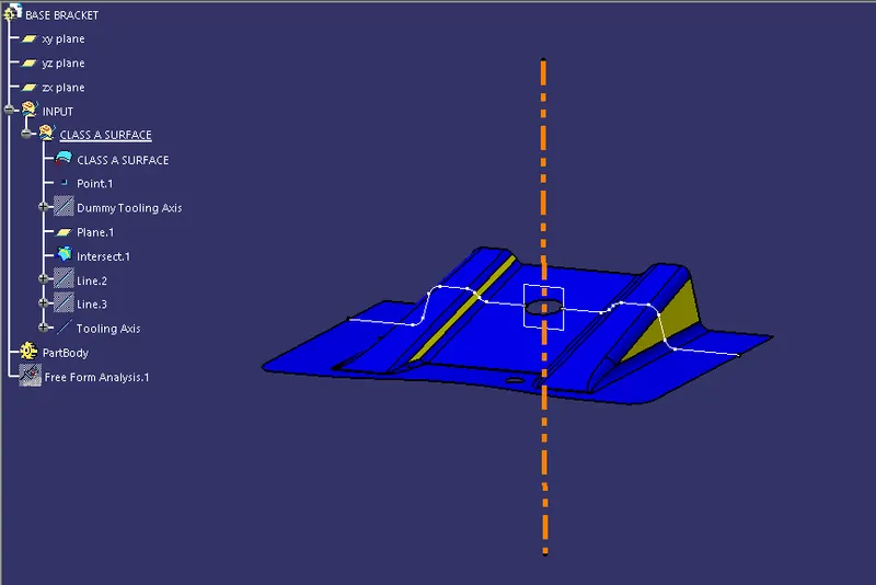
Step 6 : Using bisecting option create the tooling axis
Step 7 : Create a tooling axis folder
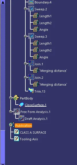
Step 8 : Perform draft analysis
Step 9 : Drag the compass on the tooling axis
Step 10 : Check the required data
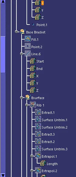
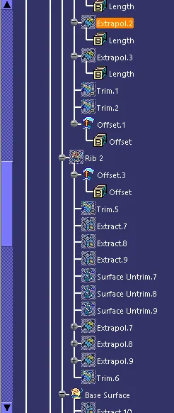
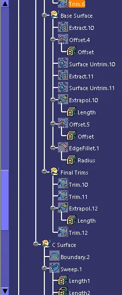
Step 11 : Extract the surface, untrim it and make an offset.
Step 12 : apply boundary feature to the surface
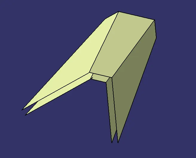
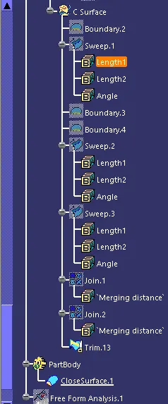
Step 13 : Use sweep feature to perform cut
Step 14 : Trim the surfaces
Step 15 : Use Close Surface Feature