Week 11 - Final project
DESIGN DEVELOPMENT OF DOOR TRIM
INTRODUCTION
The primary or major material used in automotive is metals. But all parts of a fully functioning automotive doesn’t require metals only to finish its job. The family of material we are going to use primarily depends on its function and manufacturing feasibility. Metals are obvious choice while considering the structure of a car. While designing the interior of a car it is much like building a home. The interior is where the customer is going to occupy and enjoy the journey. It has to give some good looking pleasant experience. The interior is not going to experience any kind of external force, it is going to be a cosmetic for the cabin. Therefore the point of using metals seems feeble. Hence we can choose plastics for satisfying these functions and also seems cost effective. The interior trim parts are all completely made up of plastics and its blends. The trim parts are available all over the car.
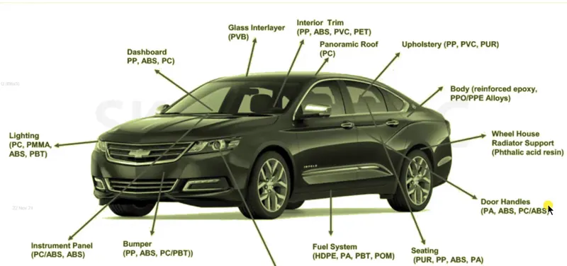
In which the door trim components are also an important design.
The major door trim components are arm rest, inner map pocket, outer map pocket and lower substrate. Every individual trim parts are having a specific purpose to fulfil the customer need. For example, there will be the instrumentation dash board which contains speedometer, fuel level, some smart apps, charging port for mobile, etc. These kind of basic customer needs can be satisfied by these trim parts all over the interior of car.
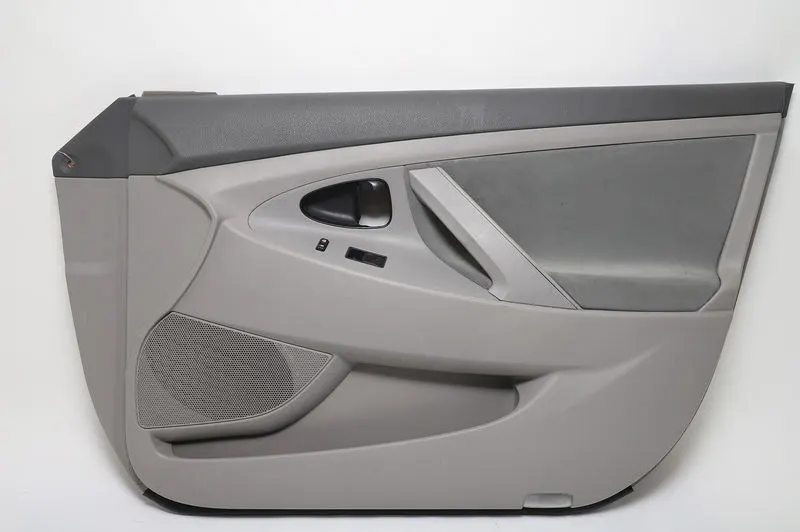
INPUTS
- Class A
- Master sections
COMPONENTS
- Arm rest
- Inner map pocket
- Outer map pocket
- Lower substrate
ARM REST
SURFACE TO SOLID BODY GENERATION
1. GIVEN CLASS A
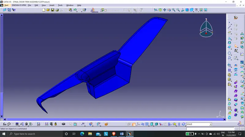
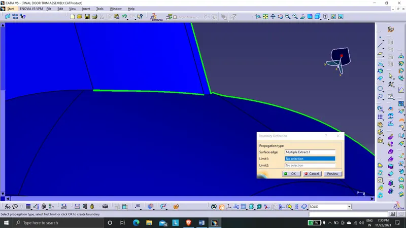
BOUNDRY CHECK :
Boundary check is performed for ensuring whether the given class A surface have any inner loops or discontinuities.
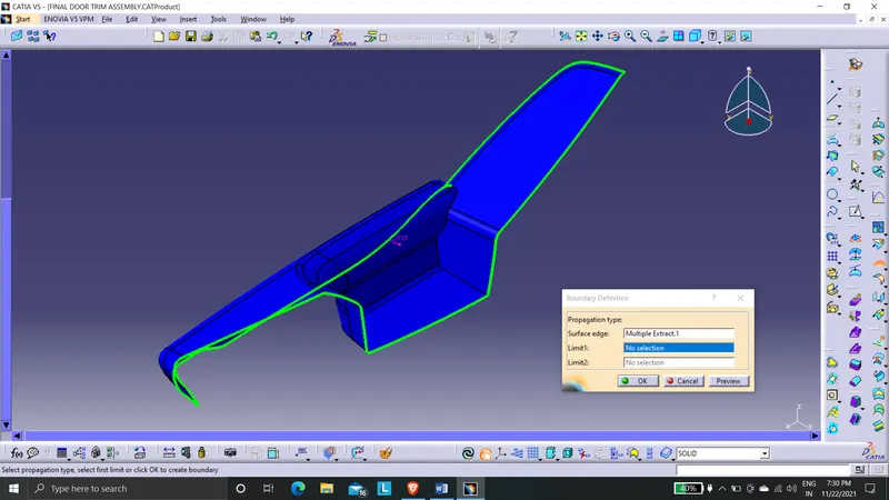
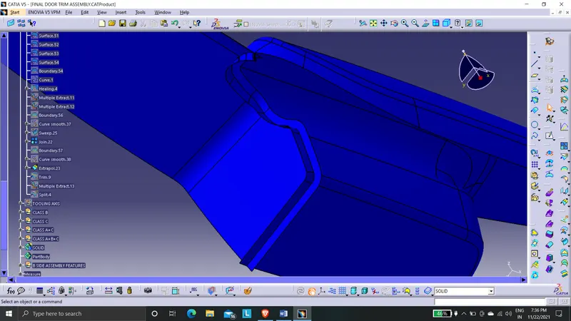
SURFACE PATCH UP :
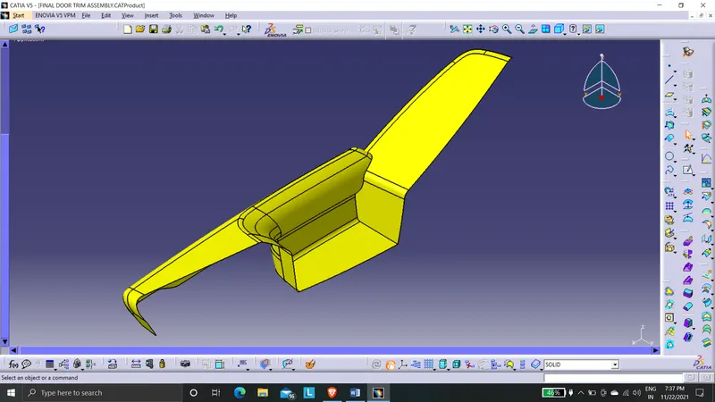
BOUNDARY CHECK :
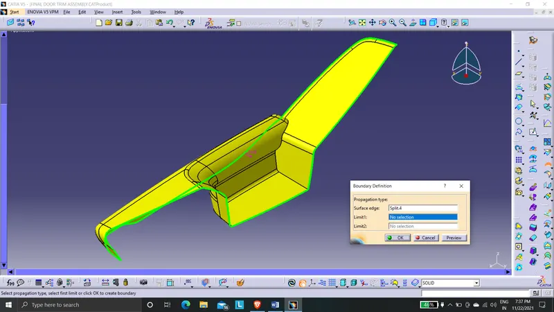
Now it seems there is’nt any discontinuities.
2. TOOLING AXIS
MAIN TOOLING AXIS :
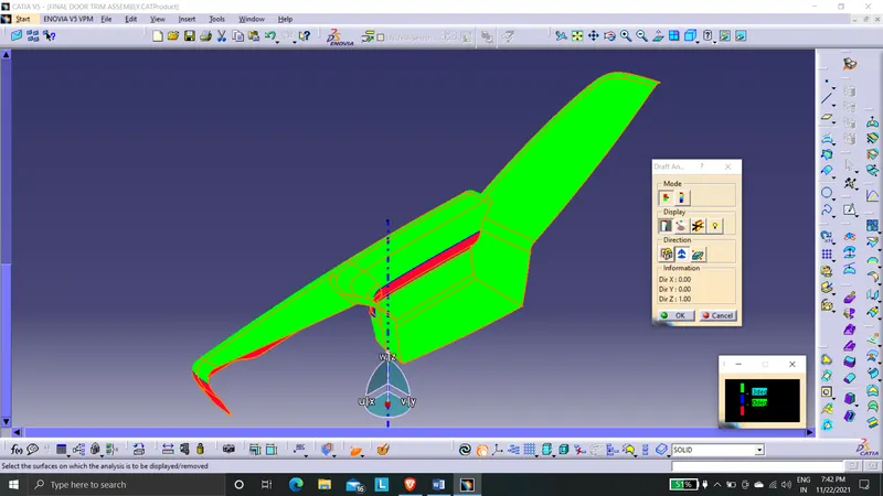
SIDE CORE TOOLING AXIS :
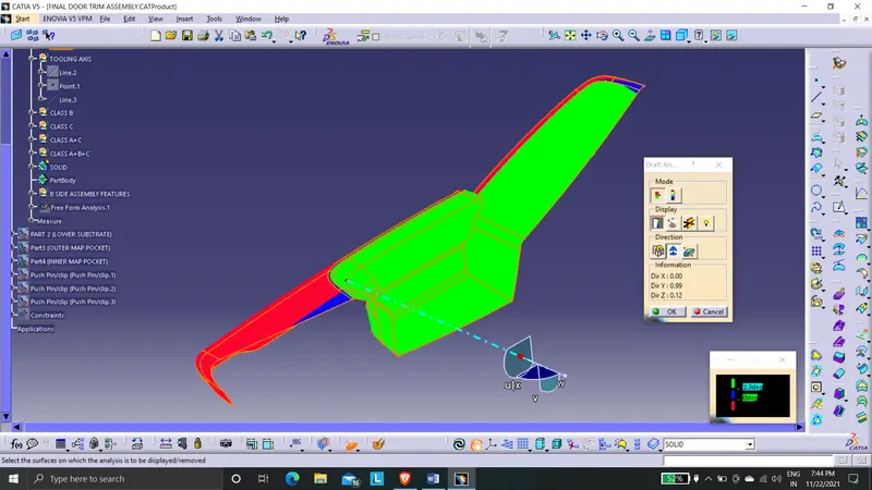
3. CLASS B
The thickness of this plastic component is found from the master section given.
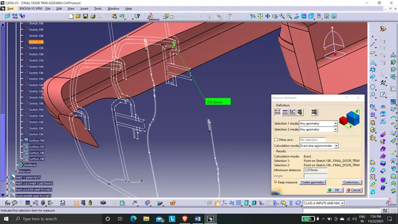
The thickness is found to be 2.5mm. Therefore the offst distance is 2.5mm from class A.
SURFACE OFFSET FAILURE :
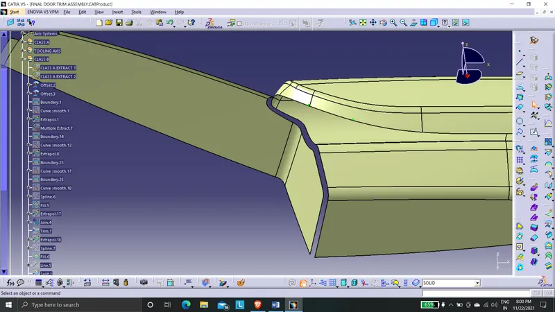
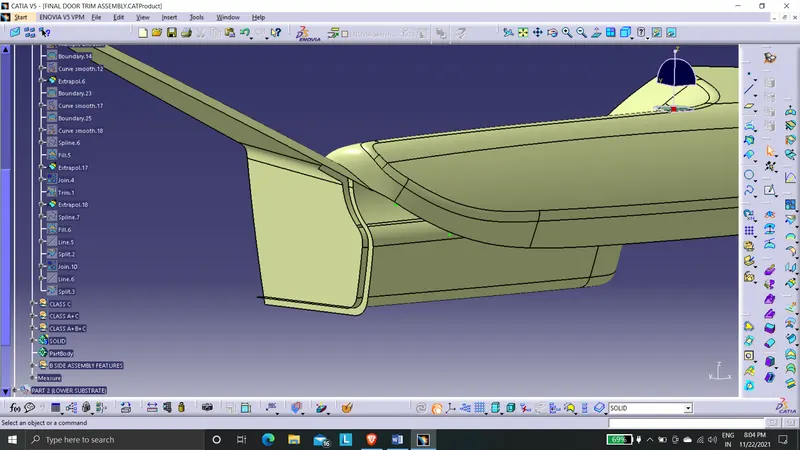
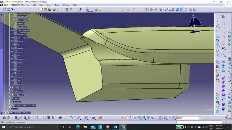
The complete class A surface can't be offsetted, this will result in offset failure. Therefore the class A is extracted as two individual piece of surfaces and then it is offsetted by 2.5mm. There will be gap between those intercepting surfaces. This can be rectified by extrpolating the edges and then trimming them to from a complete class B surface.
4. CLASS C
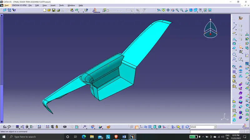
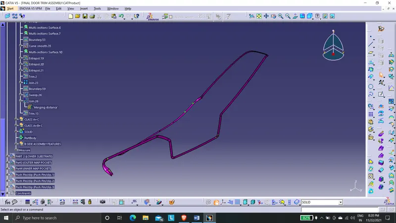
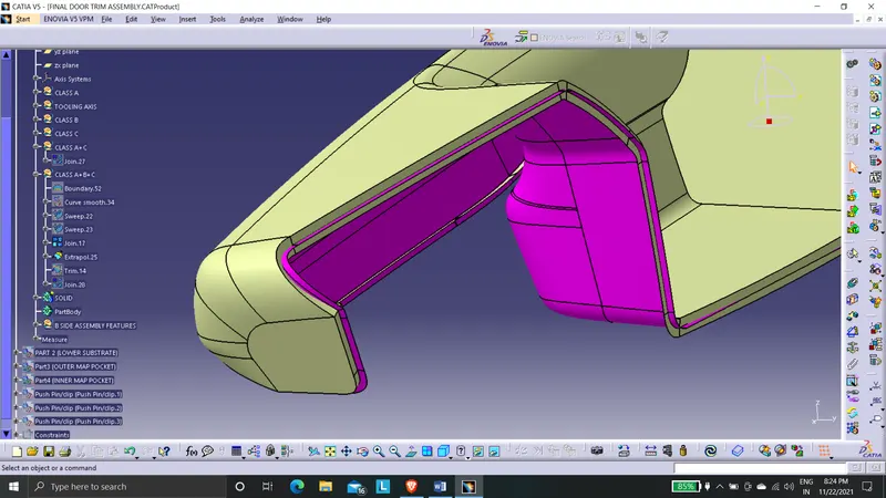
This is the connecting surface for class A and class B. This is generated mainly using the edges of the class A. We cannot use class B edges because it will resullt in trimming the class A. Therefore creating the boundary edges from class A and then using the sweep command with a draft of 3 degrees along the predetermined tooling axis.
5. CLOSED SOLID SURFACE
CLASS A+B+C :
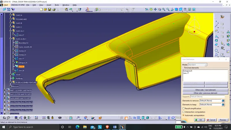
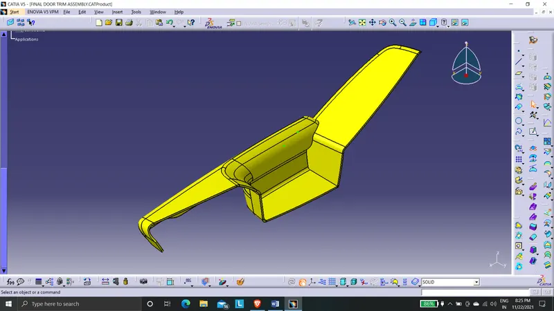
Trim the surfaces from class B to get the final output class A+B+C.
SOLID BODY :
Use closed surface command to create a solid part.
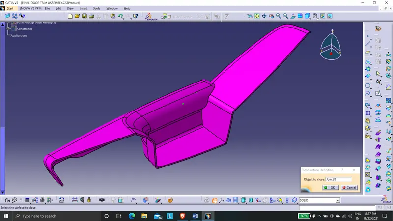
Thus the surface generation process is completed. This is the expected 3D CAD model as a output from class A.
ASSEMBLY STRATEGY
Available assembly techniques for plastics are
1. Screw bosses
2. Heat staking
3. Press fit
4. Snap fit
5. Push pin inserts
There are also some assembly techniques like ultrasonic welding, Adhesive boding, etc are available. But the above mentioned methods are for design purposes. In this arm rest component screw boss and heat staking are the assembly tehnique. These assembly features are called B side features.
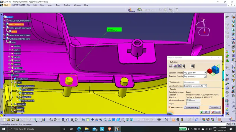
1.HEAT STAKE FLANGE DESIGN
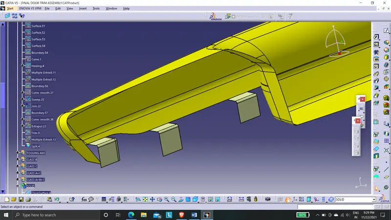
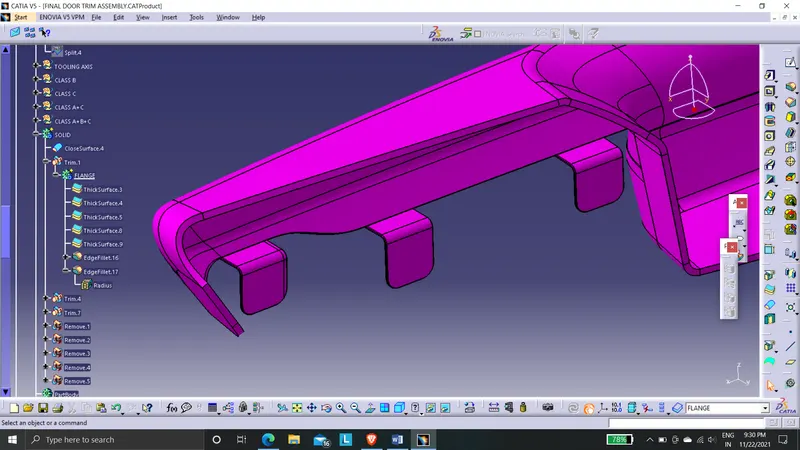
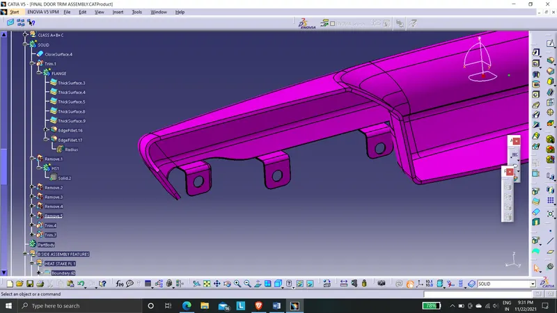
The flanges are given a thickness of 1.5mm. It has given a corner radius of 5mm. This corner radius will make sure the uniform thickness. At the center there will be heat stake hole, it is given with a 0.2mm clearence.
2. SCREW BOSS DESIGN
GUIDELINES :
- THICKNESS (W)
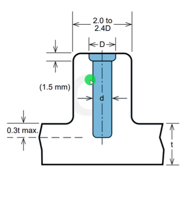
Screw boss thickness should be 0.4 or 0.5 times the wall thickness. Very thin results in poor mold filling ability.
W = 0.4 * t mm
In this case the outer diameter of boss is 2.4 times screw diameter used.
- FILLET RADIUS
Optimal fillet radius is 0.25mm.
- HEIGHT
Height to diameter ratio taken is 3:1 for steel whereas the nominal ratio is 2:1. It can project up to 0.3 times wall thickness of component.
- DRAFT
The minimum draft for boss walls is 0.5 degrees.
- Bosses can’t be attaches to side walls. This might leads to runner lines and sinkage of material. We can either provide connecting ribs for bosses or open boss design for bosses near side walls.
PROCEDURE :
- Sketch the boss profile in the base surface.
- Inset a new body.
- Pad the profile. Thicken it.
From design rule,
I am choosing a M6 bolt. Its major diameter will be 6mm. Tap drill size would be approximately 5.0mm.
Outer diameter D = 2.4 * d
= 2.4 * 5.0
= 12mm
- Change the extruded height to 15mm
- Draft is given of about 0.5 degrees.
From design rule,
The minimum drat angle for boss is +/- 0.5 degrees.
- All the edges are given 0.25mm maximum fillet radius.
- Now we can create ribs on bosses to stiffen it.
- Extract the surface on which the rib is to be designed.
- Draw a line and extrude it to create a surface.
- Inset a new body
- Thicken the surface by 1mm.
From design rule,
W = 0.4 * t
= 0. * 2.5
= 1mm
- Change the extruded height to 12.5mm
From design rule,
H = 5 * t
= 5 * 1
= 5mm
- Draft is given of about 0.5 degrees.
From design rule,
The minimum drat angle for ribs is +/- 0.5 degrees.
- All the edges are given 0.25mm maximum fillet radius.
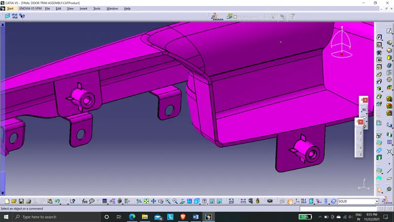
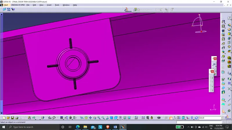
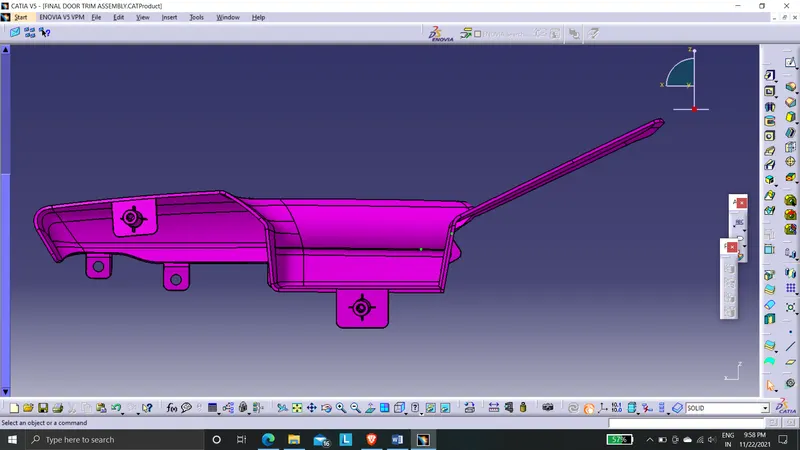
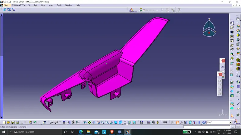
ARM REST :
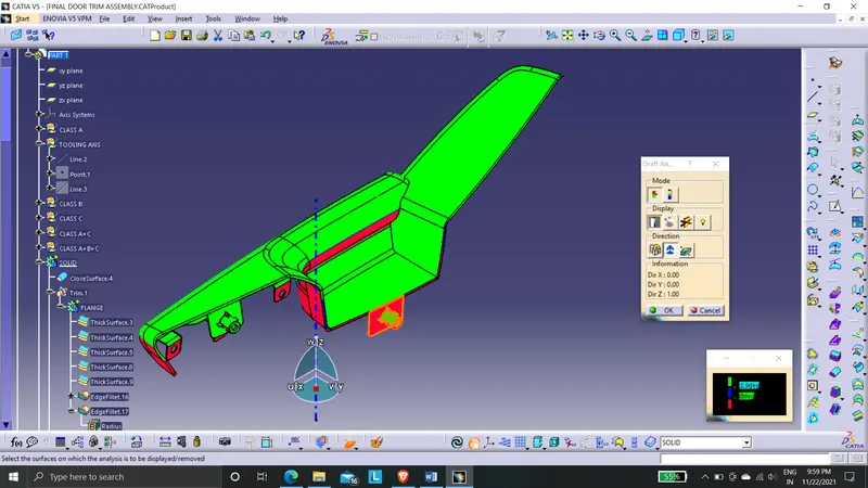
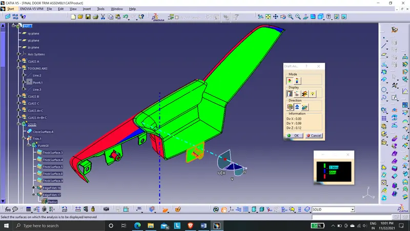
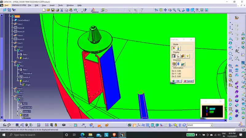
DRAFT ANALYSIS :
INNER MAP POCKET
SURFACE TO SOLID BODY GENERATION
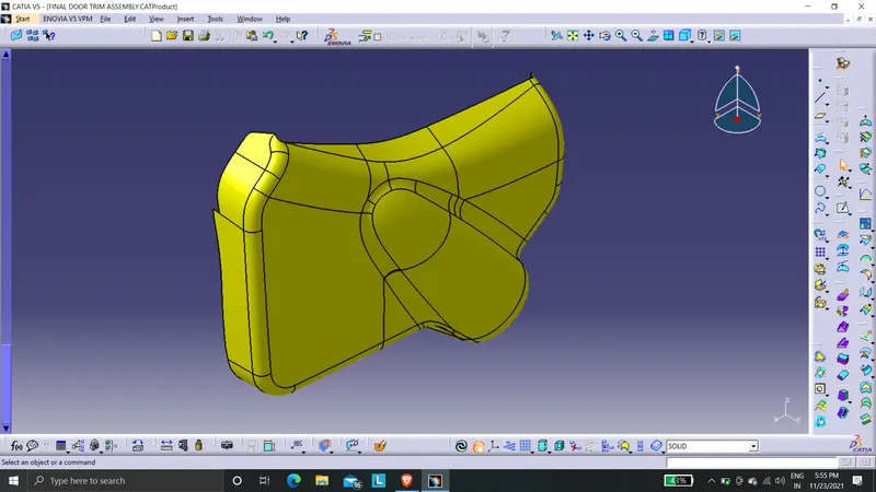
1. GIVEN CLASS A
BOUNDRY CHECK :
Boundary check is performed for ensuring whether the given class A surface have any inner loops or discontinuities.
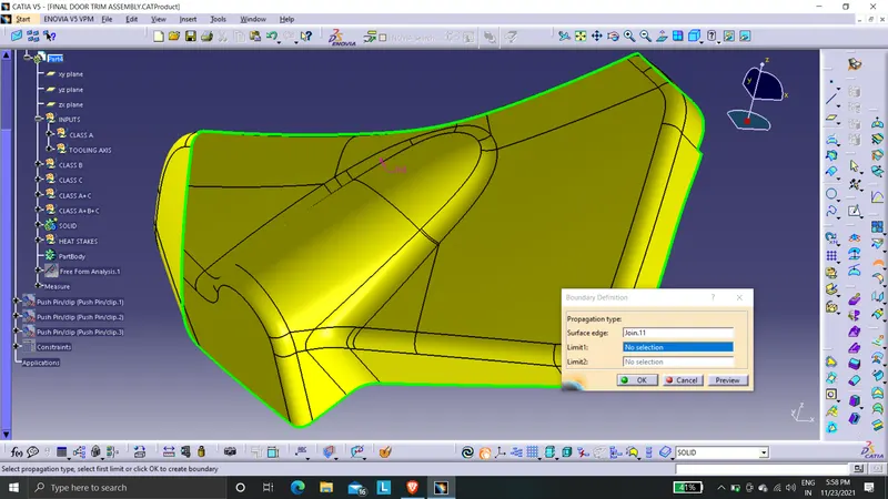
There is not any boundary discontinuities or inner closed loops.
2. TOOLING AXIS
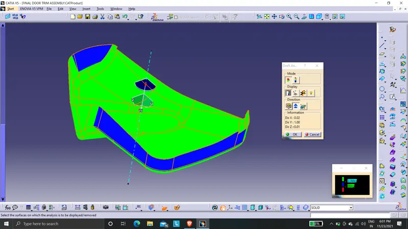
MAIN TOOLING AXIS :
3. CLASS B
The thickness of this plastic component is found from the master section given. The thickness is found to be 2.5mm. Therefore the offst distance is 2.5mm from class A.
SURFACE OFFSET FAILURE :
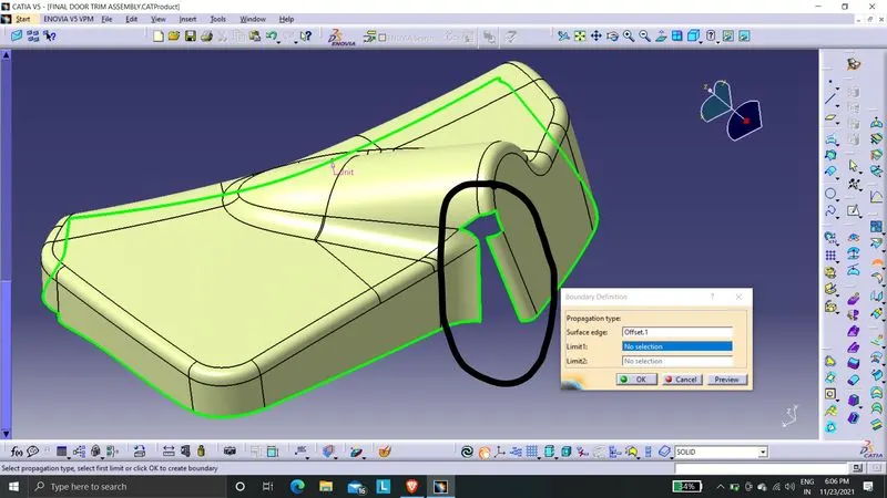
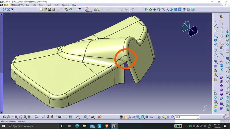
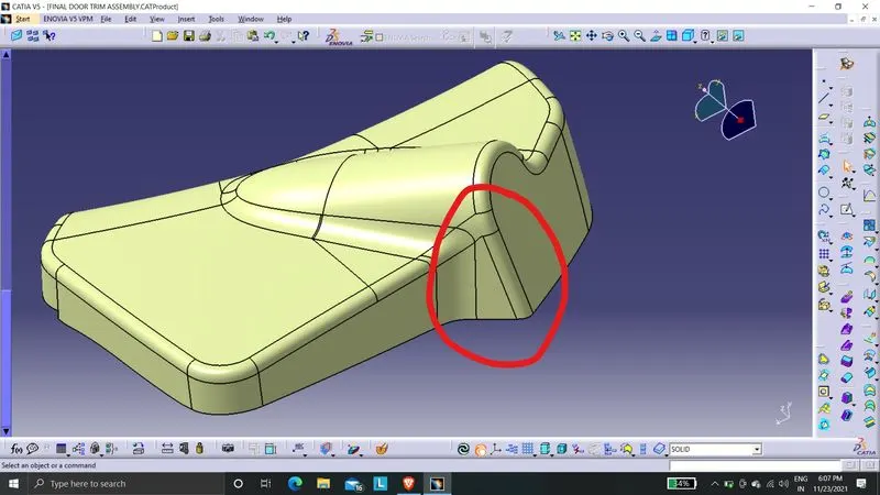
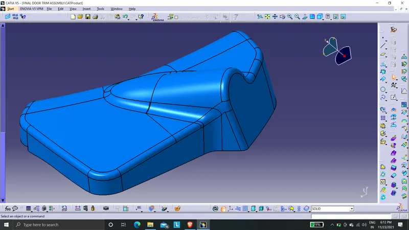
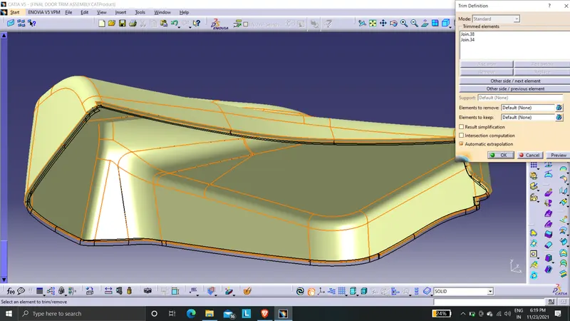
The complete class A surface can't be offsetted, this will result in offset failure. Some surfaces marked in black region will fail after offsetting. Therefore those surfaces has to be created using fill command.
4. CLASS C
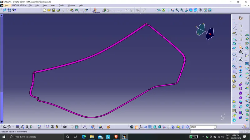
This is the connecting surface for class A and class B. This is generated mainly using the edges of the class A. We cannot use class B edges because it will resullt in trimming the class A. Therefore creating the boundary edges from class A and then using the sweep command with a draft of 3 degrees along the predetermined tooling axis.
5. CLOSED SOLID SURFACE
CLASS A+B+C :
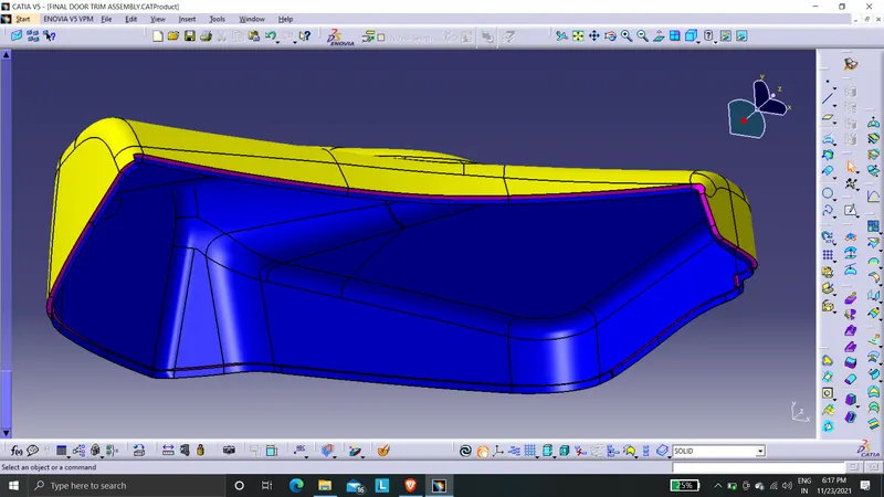
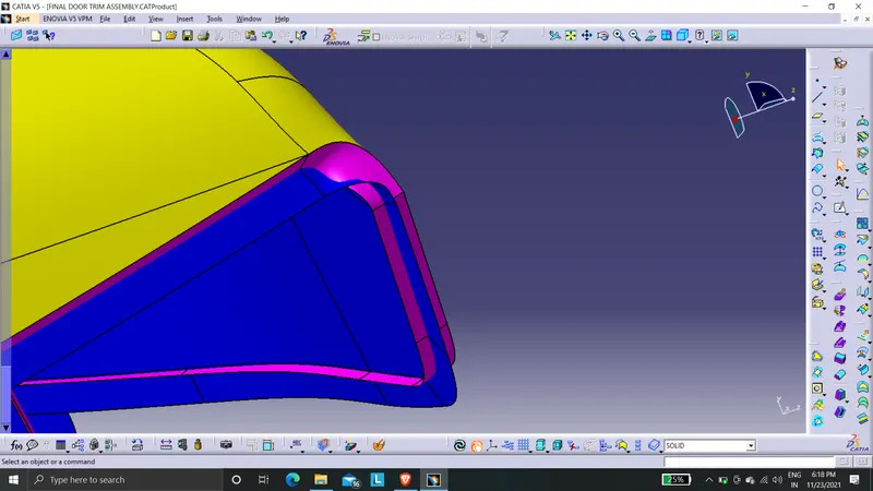
Trim the surfaces from class B to get the final output class A+B+C.
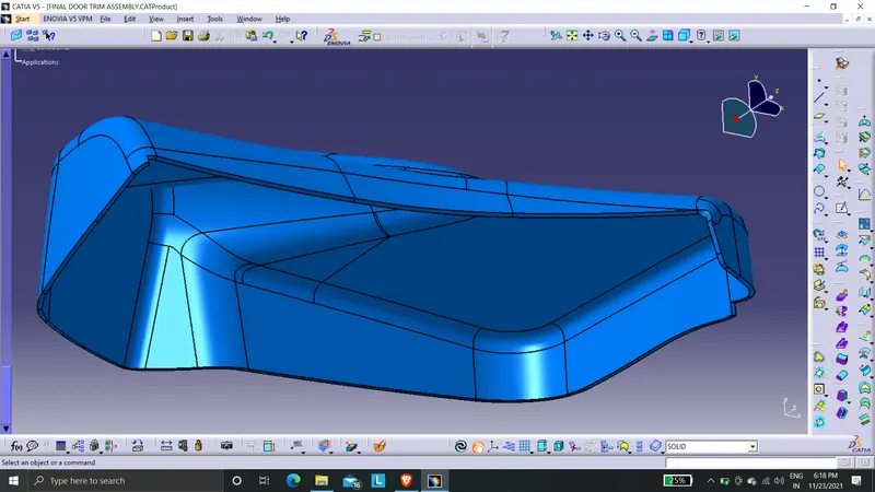
SOLID BODY :
Use closed surface command to create a solid part.
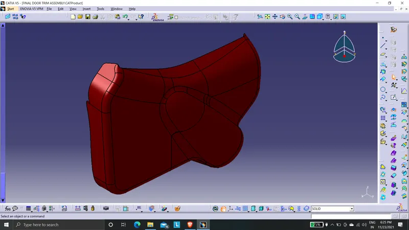
Thus the surface generation process is completed. This is the expected 3D CAD model as a output from class A.
ASSEMBLY STRATEGY
Available assembly techniques for plastics are
1. Screw bosses
2. Heat staking
3. Press fit
4. Snap fit
5. Push pin inserts
There are also some assembly techniques like ultrasonic welding, Adhesive boding, etc are available. But the above mentioned methods are for design purposes. In this inner map pocket component heat staking is the assembly tehnique. These are called B side assembly features.
This inner map pocket will be heat staked with the lower substrate.
1.HEAT STAKE FLANGE DESIGN
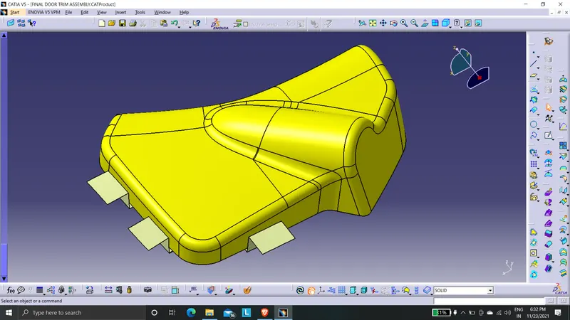
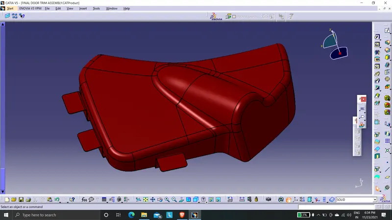
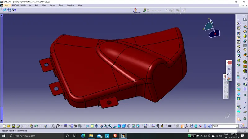
The flanges are given a thickness of 1.5mm. It has given a corner radius of 5mm. This corner radius will make sure the uniform thickness. At the center there will be heat stake hole, it is given with a 0.2mm clearence.
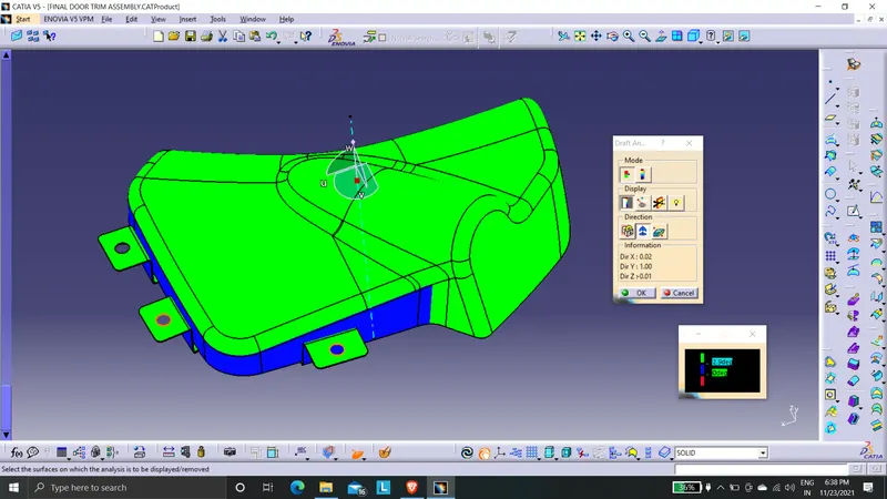
DRAFT ANALYSIS :
OUTER MAP POCKET
SURFACE TO SOLID BODY GENERATION
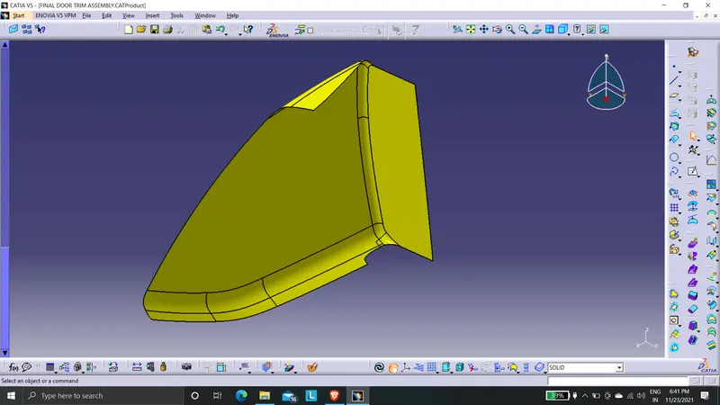
1. GIVEN CLASS A
BOUNDRY CHECK :
Boundary check is performed for ensuring whether the given class A surface have any inner loops or discontinuities.
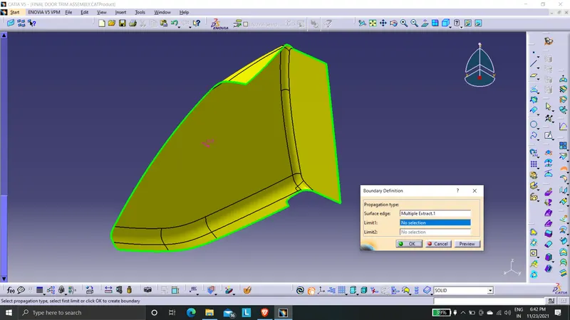
There is not any boundary discontinuities or inner closed loops.
2. TOOLING AXIS
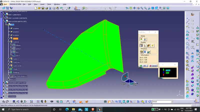
MAIN TOOLING AXIS :
3. CLASS B
The thickness of this plastic component is found from the master section given. The thickness is found to be 2.5mm. Therefore the offst distance is 2.5mm from class A.
SURFACE OFFSET FAILURE :
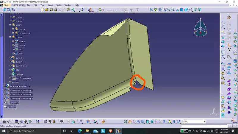
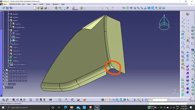
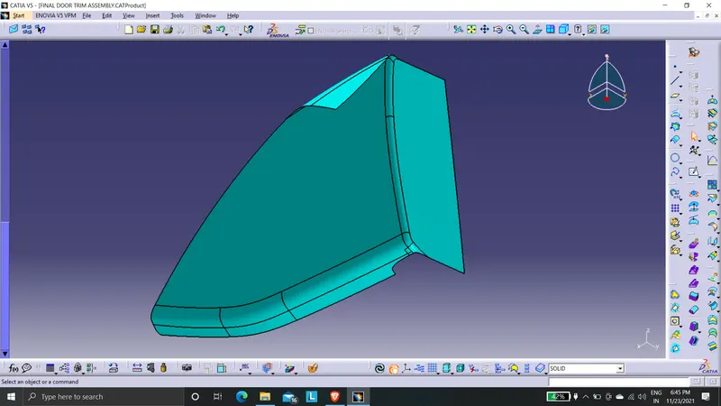
The complete class A surface can't be offsetted, this will result in offset failure. Some surfaces marked in black region will fail after offsetting. Therefore those surfaces has to be created using fill command.
4. CLASS C
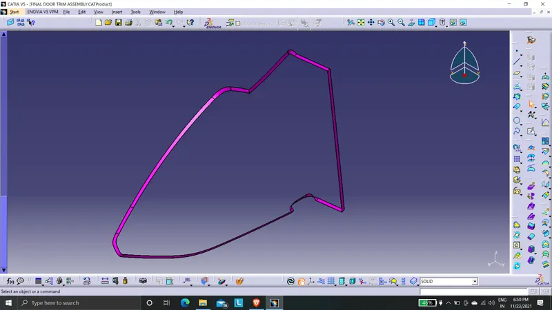
This is the connecting surface for class A and class B. This is generated mainly using the edges of the class A. We cannot use class B edges because it will resullt in trimming the class A. Therefore creating the boundary edges from class A and then using the sweep command with a draft of 3 degrees along the predetermined tooling axis.
5. CLOSED SOLID SURFACE
CLASS A+B+C :
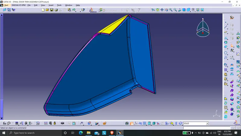
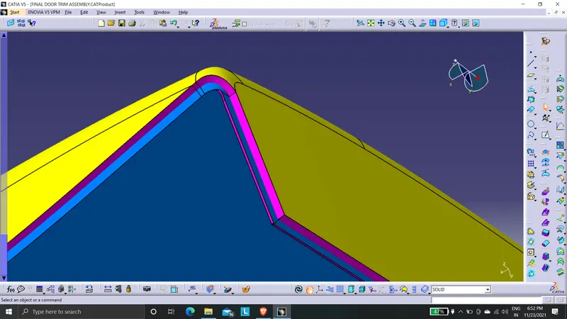
Trim the surfaces from class B to get the final output class A+B+C.
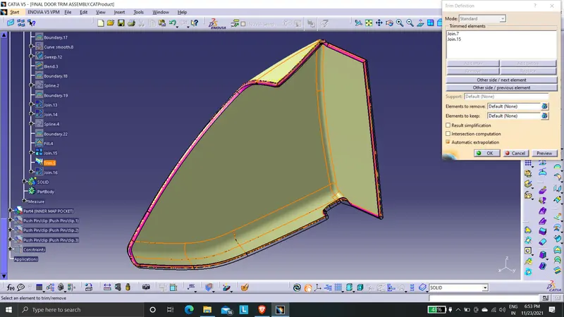
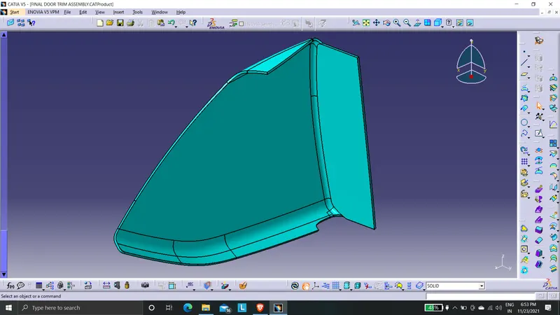
SOLID BODY :
Use closed surface command to create a solid part.
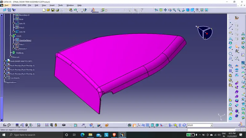
Thus the surface generation process is completed. This is the expected 3D CAD model as a output from class A.
ASSEMBLY STRATEGY
Available assembly techniques for plastics are
1. Screw bosses
2. Heat staking
3. Press fit
4. Snap fit
5. Push pin inserts
There are also some assembly techniques like ultrasonic welding, Adhesive boding, etc are available. But the above mentioned methods are for design purposes. In this inner map pocket component heat staking is the assembly tehnique. These are called B side assembly features.
This outer map pocket will be heat staked with the lower substrate.
1.HEAT STAKE FLANGE DESIGN
The flanges are given a thickness of 1.5mm. It has given a corner radius of 5mm. This corner radius will make sure the uniform thickness. At the center there will be heat stake hole, it is given with a 0.2mm clearence.
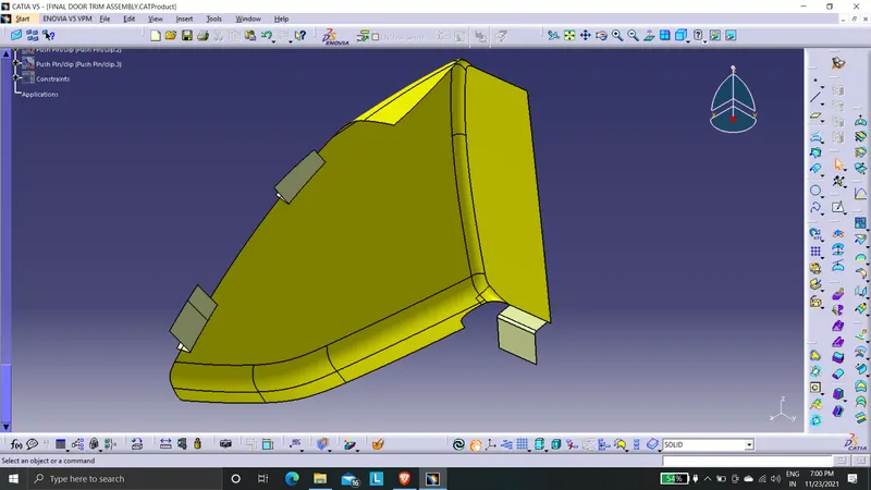

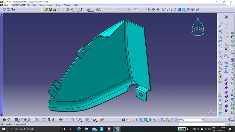
The flanges are given a thickness of 1.5mm. It has given a corner radius of 5mm. This corner radius will make sure the uniform thickness. At the center there will be heat stake hole, it is given with a 0.2mm clearence.
OUTER MAP POCKET
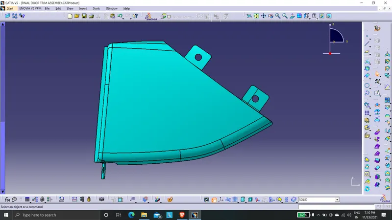
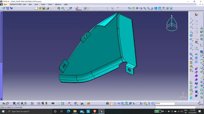
DRAFT ANALYSIS :
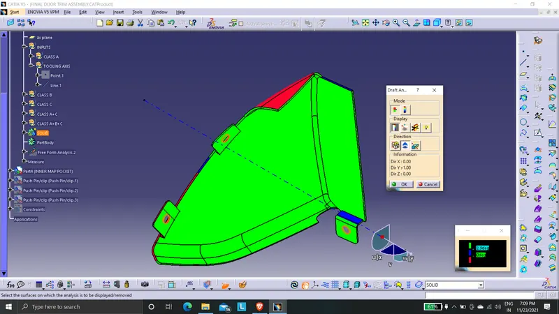
LOWER SUBSTRATE
SURFACE TO SOLID BODY GENERATION
1. GIVEN CLASS A
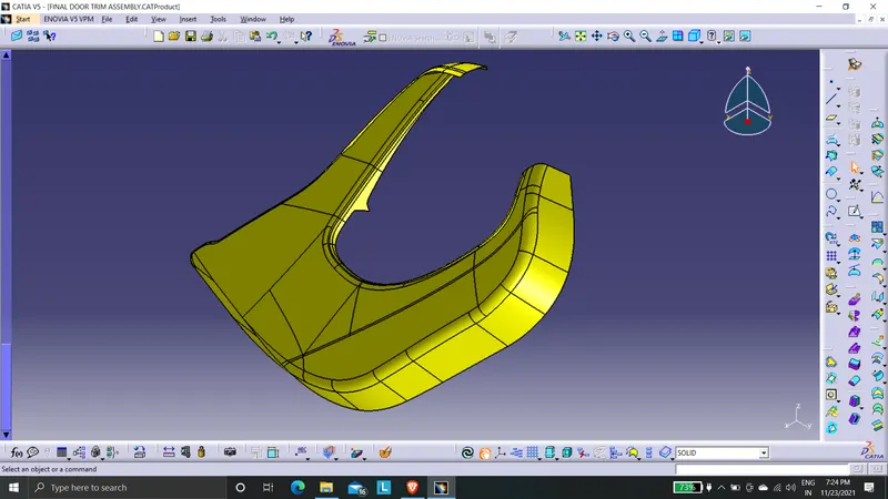
BOUNDRY CHECK :
Boundary check is performed for ensuring whether the given class A surface have any inner loops or discontinuities.
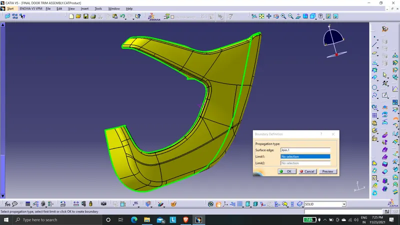
There is not any boundary discontinuities or inner closed loops.
2. TOOLING AXIS
MAIN TOOLING AXIS :
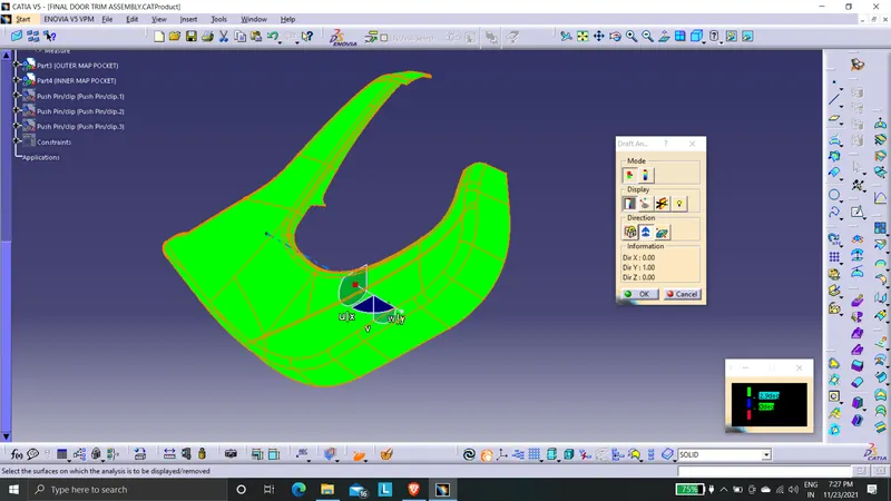
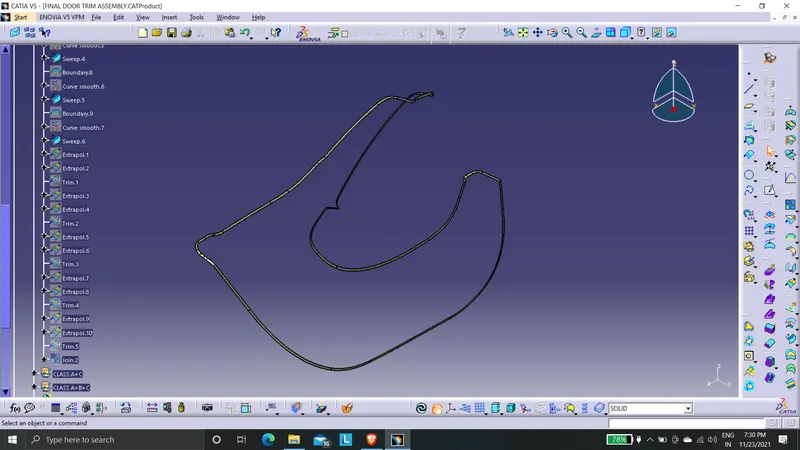
3. CLASS B
The thickness of this plastic component is found from the master section given. The thickness is found to be 2.5mm. Therefore the offst distance is 2.5mm from class A.
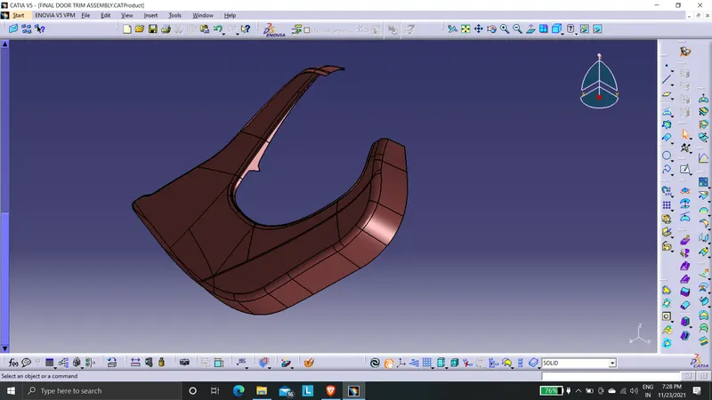
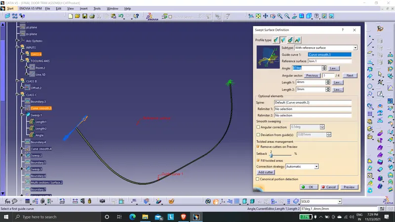
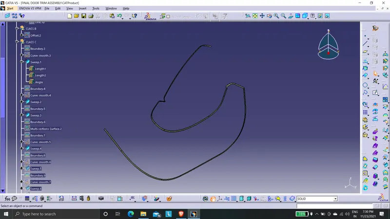
4. CLASS C
This is the connecting surface for class A and class B. This is generated mainly using the edges of the class A. We cannot use class B edges because it will resullt in trimming the class A. Therefore creating the boundary edges from class A and then using the sweep command with a draft of 3 degrees along the predetermined tooling axis.
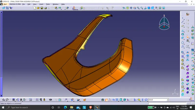
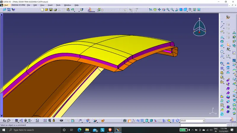
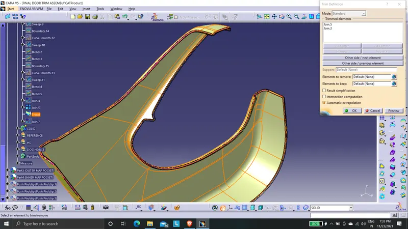
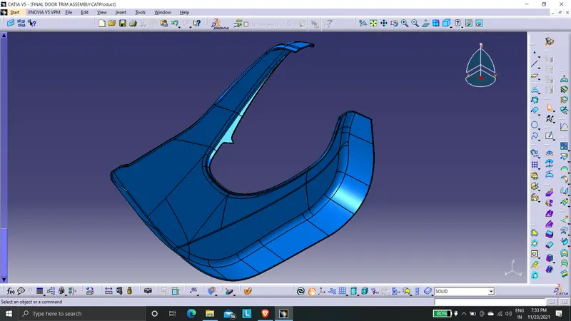
5. CLOSED SOLID SURFACE
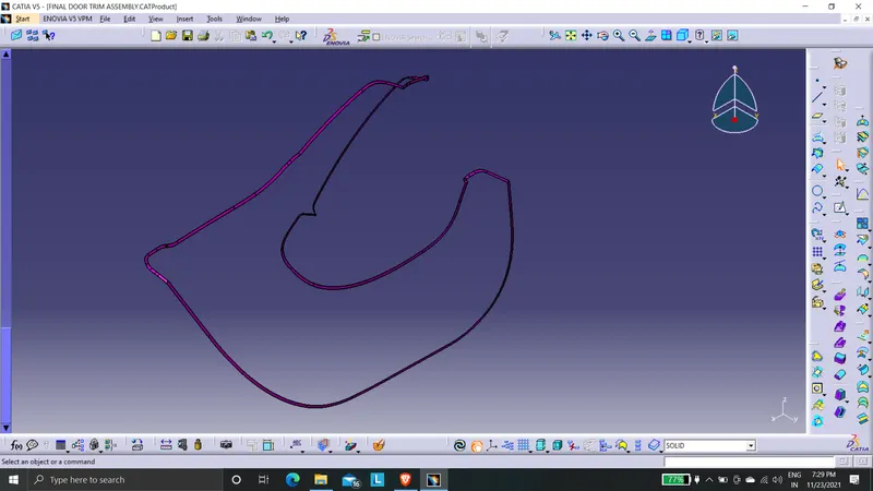
CLASS A+B+C :
Trim the surfaces from class B to get the final output class A+B+C.
SOLID BODY :
Use closed surface command to create a solid part.
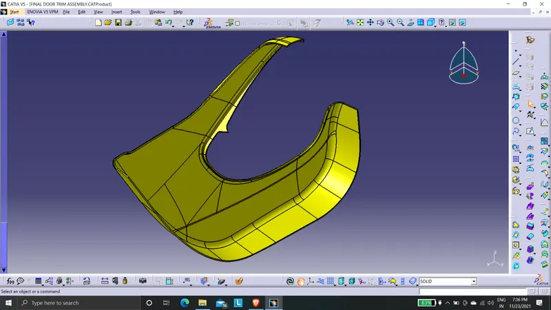
Thus the surface generation process is completed. This is the expected 3D CAD model as a output from class A.
ASSEMBLY STRATEGY
Available assembly techniques for plastics are
1. Screw bosses
2. Heat staking
3. Press fit
4. Snap fit
5. Push pin inserts
There are also some assembly techniques like ultrasonic welding, Adhesive boding, etc are available. But the above mentioned methods are for design purposes. In this inner map pocket component heat staking is the assembly tehnique. These are called B side assembly features.
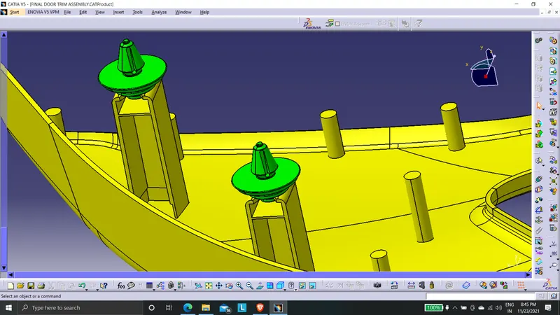
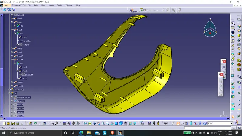
This lower substrate will have the heat stakes upon which other components will be attached, whereas the lower substrate will be push pin clipped with door body as one single unit.
1. DOG HOUSE DESIGN
This dog house is designed for incorporating the push pin clips at required heights from locating points.
GUIDELINES :
- THICKNESS (W)
The dog house thickness at the junction with the class B surface should be 0.4 times the main wall thickness or less than that. This slight change in cross section assist in mold filling ability.
W = 0.4 * t mm
- FILLET RADIUS
Optimal fillet radius is 0.25mm. By smoothening the corners we can reduce presure drop and stress concentration problems.
- HEIGHT
The height of the contraction in dog house can be 3 to 6mm from B surface. The minimum height of dog house should be 6mm. Less than this height may reduce the strength.
4. WIDTH
The width of the dog house should have a minimal value of 12mm.
For steel width/height ratio is 3:1, prefered ratio is 2:1
5. DRAFT
The minimum draft for boss walls is +/-1.5 degrees.
PROCEDURE :
- Sketch a 20*20 square profile in the base surface.
- Do surface extrude on it. The minimum specified height is 6mm. we can take 21mm.
- Extract base surface, untrim it, extrapolate it and offset it by 20mm.
- Use trim command.
- Inset a new body.
- Thicken it.
From design rule,
The thickness at junction of B surface and dog house should be 0.4*t.
Therefore
Thickness at junction = 0.4 * t
= 0.4 * 2.5
= 1mm
We can take dog house thickness as 2mm.
- Extract the wall which is opposite to open side, untrim it, extrapolate it and offset it by 19mm.
- Trim the solid body.
- Draft is given of about 1.5 degrees along tooling direction Y and Z.
From design rule,
The minimum drat angle for boss is +/- 1.5 degrees.
- All the edges are given 0.25mm maximum fillet radius.
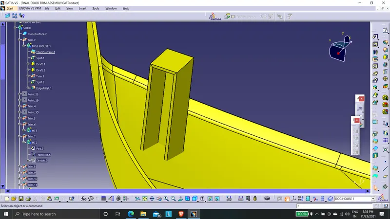
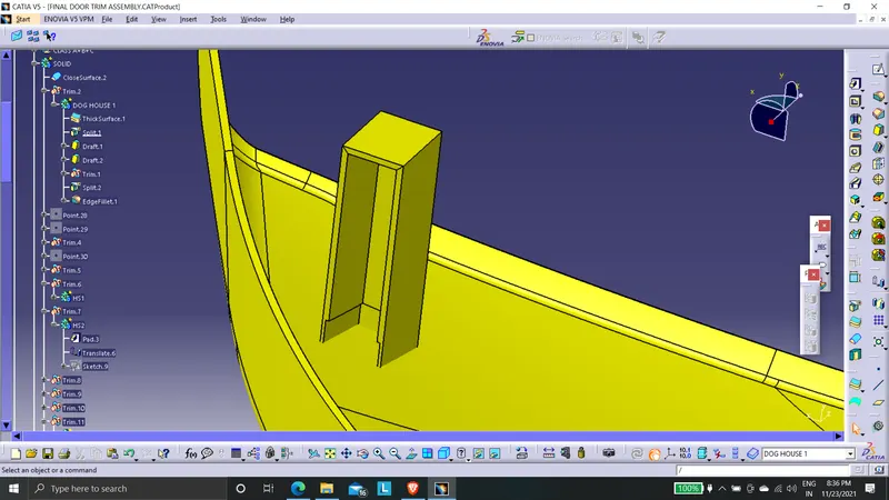
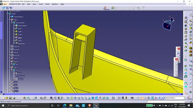
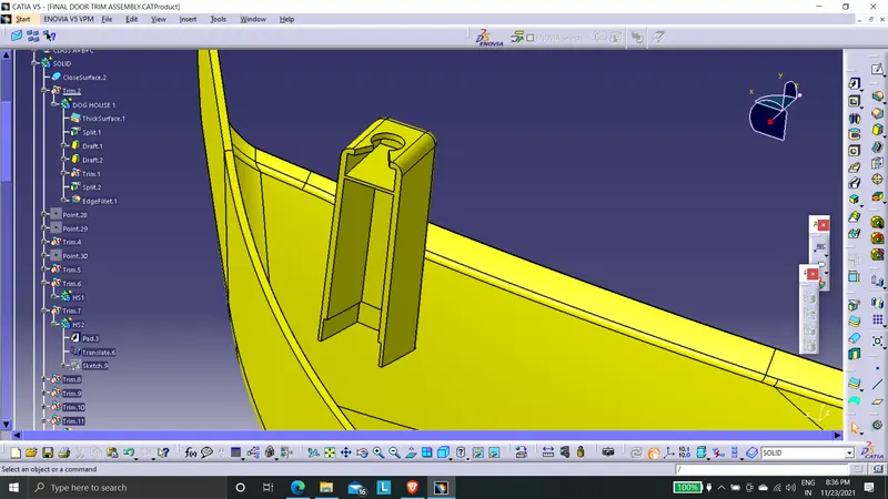
2. PUSH PIN
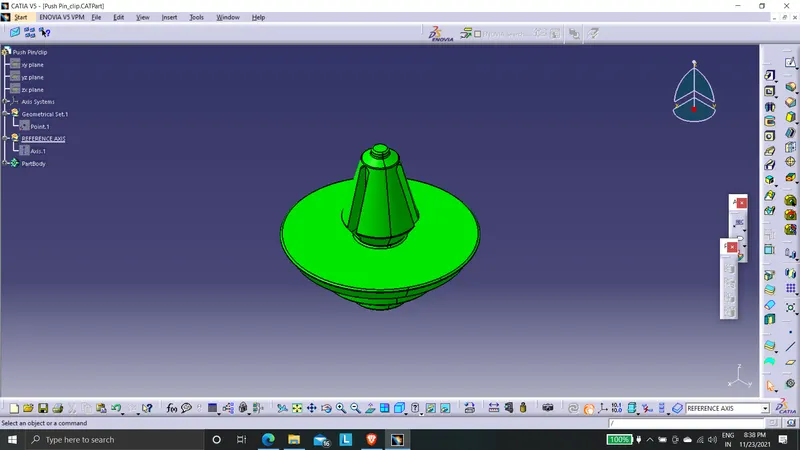
This is the insert which has been planned to be fitted with dog house. It is constrained with the dog house as below.
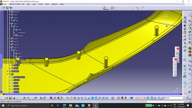
3.HEAT STAKE DESIGN
1. Create the boundary lines for the surface.
2. Offset the boundary curve on the surface.
3. Create points on offset curve bywhich these points will be in the middle of heat stake flanges already created on its mating surfaces.
4. Sketch the profile of heat stake
5. Pad the profile. The height of the profile has to be less than locators. Extend on negative direction also.
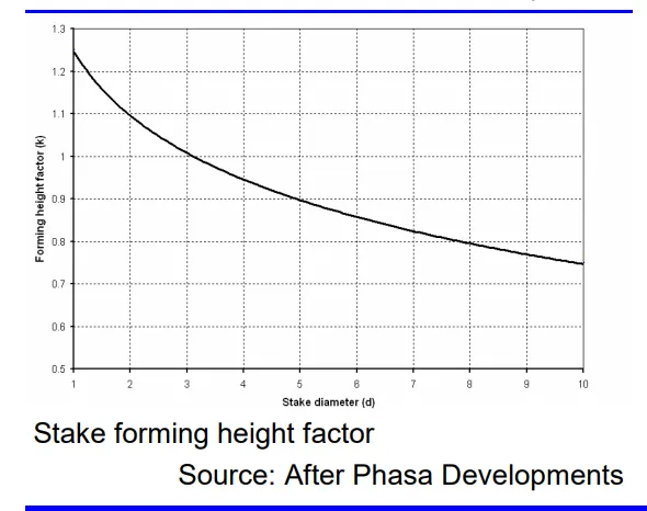
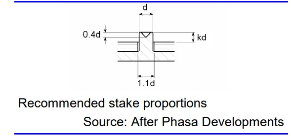
Diameter = 8mm
Stake height = 8*k
The height factor value can be approximated using above chart.
where K = 0.6
Stake height = 4mm
6. Trim the pad with the thickened surface.
7. Apply minimum draft angle of 1.5 degrees.
8. Now copy the heat stake and paste in new body.
9. Translate the copied link to the next contact point.
LOWER SUBSTRATE :
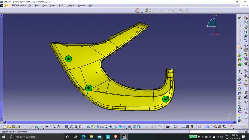
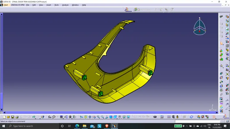
DRAFT ANALYSIS :
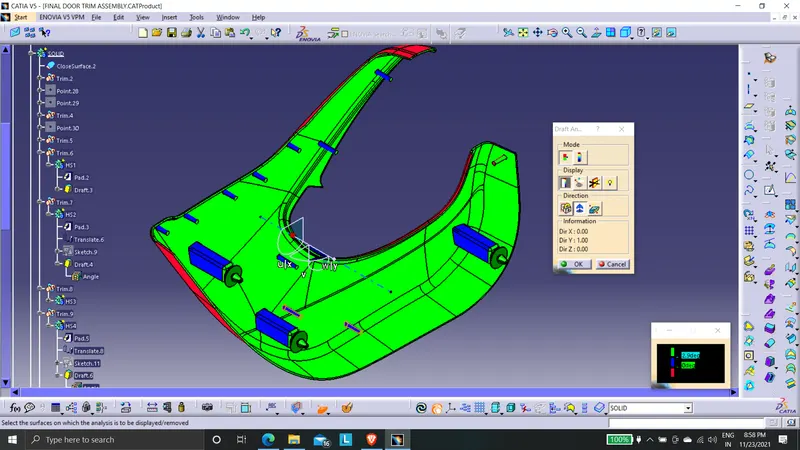
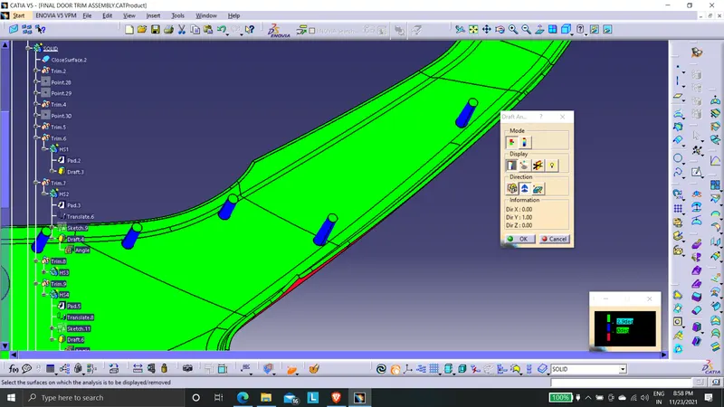
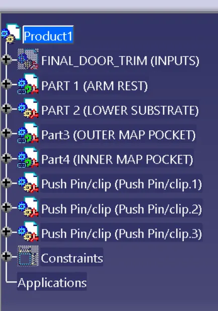
TREE STRUCTURE OF FINAL ASSEMBLY
This is top down approach CAD model.
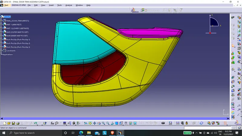
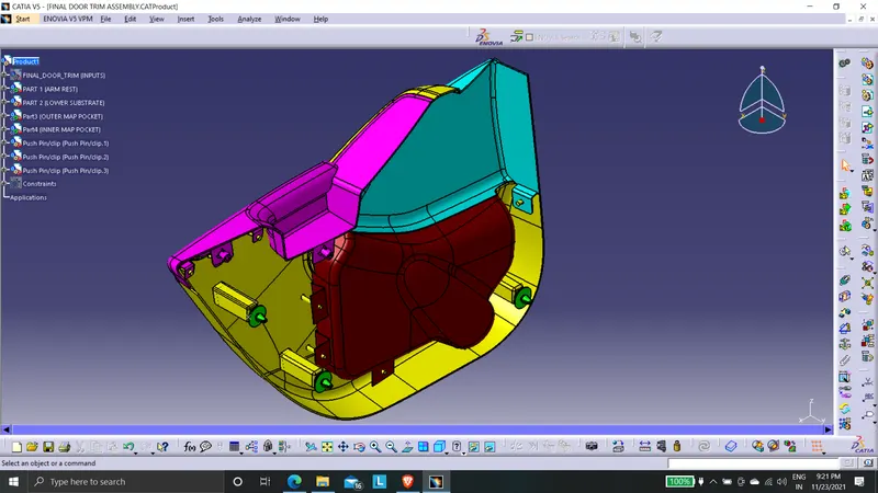
FINAL ASSEMBLY

CONCLUSION
Hence the door interior trim is designed with all the necessary attachment features.