Week 11 - Final project
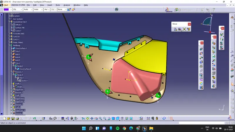
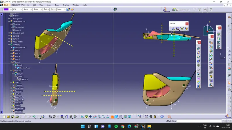
AIM: Development of a Door Trim panel.
OBJECTIVE: To make a Door trim panel in Catia V5 using the given Class A surface.
ABSTRACT: This project contains the brief theory on how the approach has been made inorder to obtain the solid door trim panel. It also show case certain rules regarding the maufacturing of plastic components. Draft analysis of the Class A surface and creation of Class B as well as Class C is also described here.
CLASS A SURFACE:
In automotive industry various teams works on various components, a car for example is not entirley designed by a single designer. There are many teams among which the task of making various components is distributed. And this is followed for every department of the industry. In this project we are given class A surface which is designed in other software like Autodesk Alias, by a Class A designer. This is aesthetic surface and a lot of time, effort and good experience are demanded for making this continuous and a good flowing surface model. This is the major reason why, when we get this as input we are not allowed as a plastic designer to make any improvements in the Class A surface. Rather, it should be brought to the attention of the seniors which later is conveyed to the concerned team and take care of.
TOOLING AXIS:
Tooling axis is the axis along which the core and cavity opens and closes. It is very important to define the tooling axis in the first step while designing a component as it is the main component which helps us to run draft analysis on class A at initial stage to see if we can move ahead. Also for later stage, tooling axis is the direction along which Class c surface and the draft to the components are given. In this model we have a tooling axis in the perpendicular direction to the entire dooe trim that is y-direction in the model. It is very evident that arm rest will require a side core, so another tooling direction is made specially for arm rest . Apart from these two tooling axises we also have a side core tooling axis for dog house.
DRAFT ANALYSIS REPORT ON VARIOUS CLASS A SURFACES:
1. Lower Substrate:
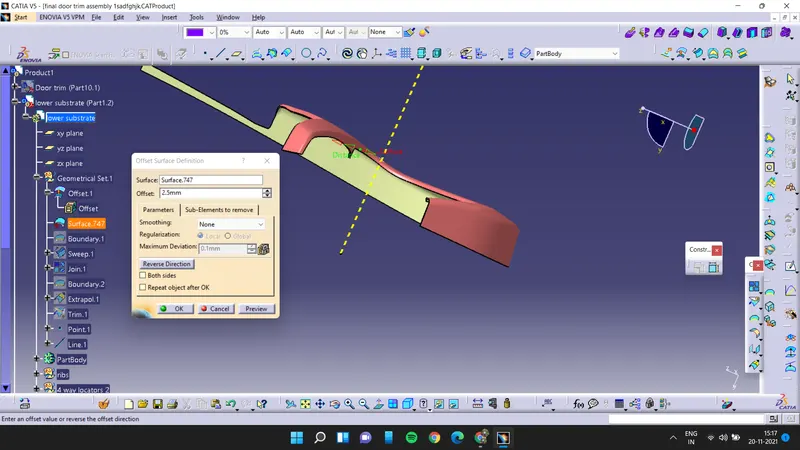
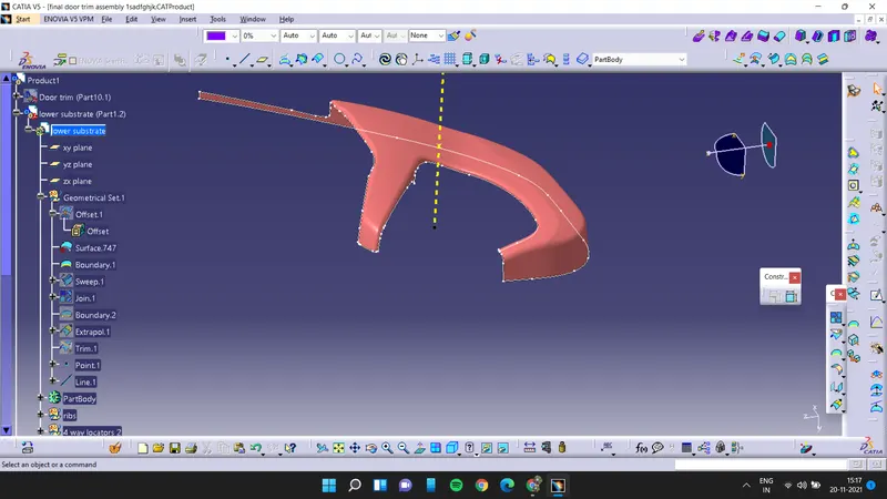
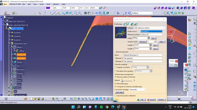
First we have to offset the class A surface for 2.5mm and then extract the edges of class A surface and extrapolate it
now sweep the class A surface
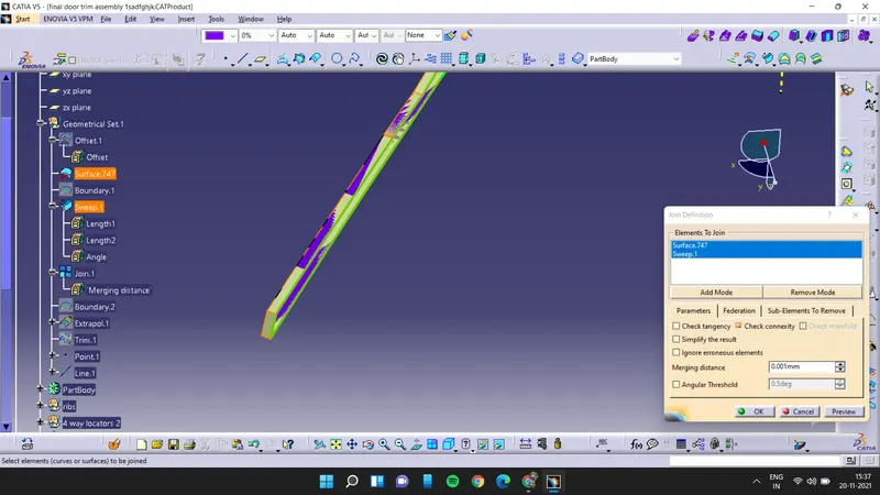
join the swept then class A surface
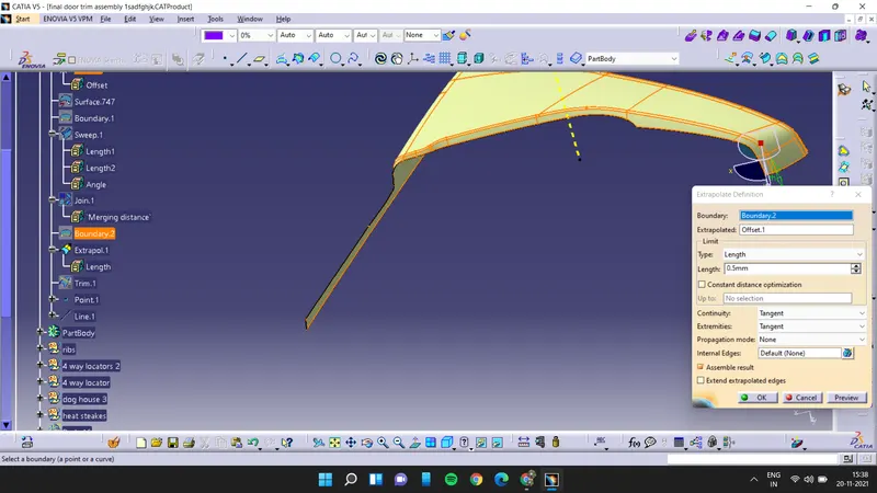
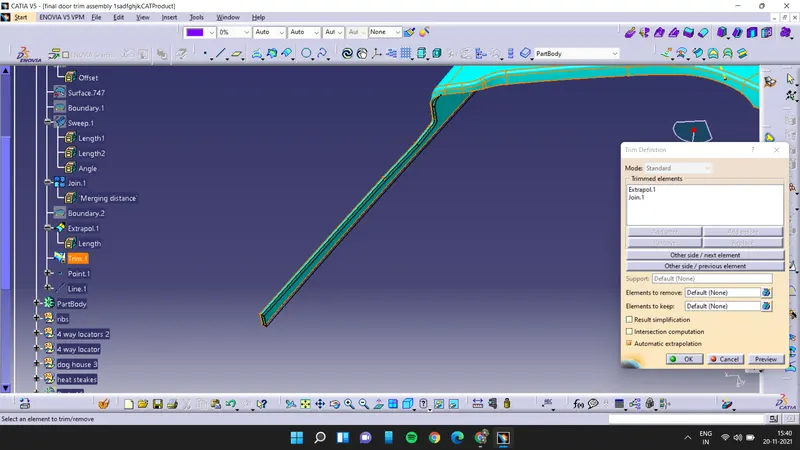
and now extrapolate the class B surface andthen trim the extrapolated surface with class A& class C
Heat Stakes:
Draw the sketch and then extrude it and then thicken it for 1mm
and draft the heat stakes for 0.5 deg. and assemble it with the lower substarte
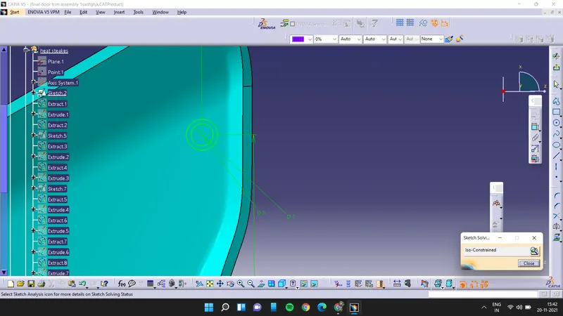
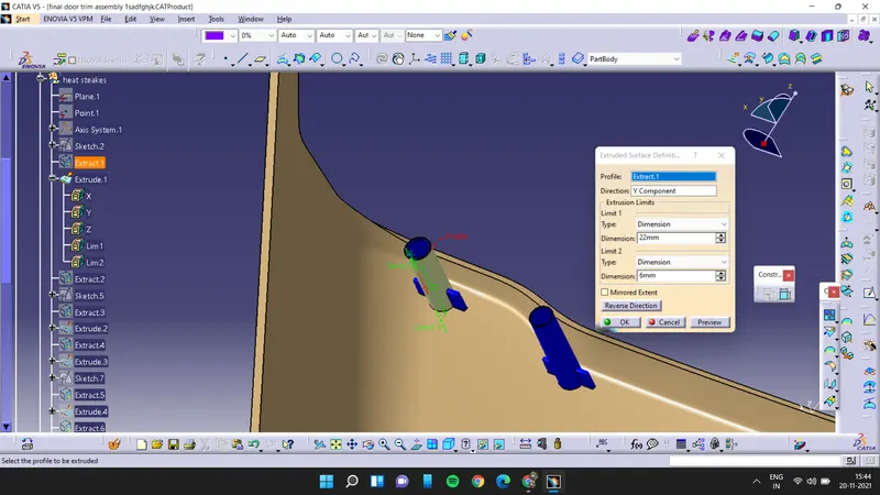
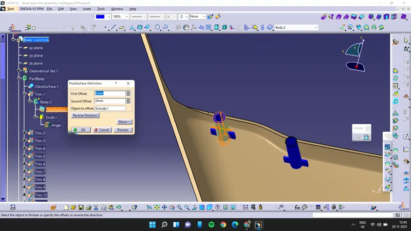
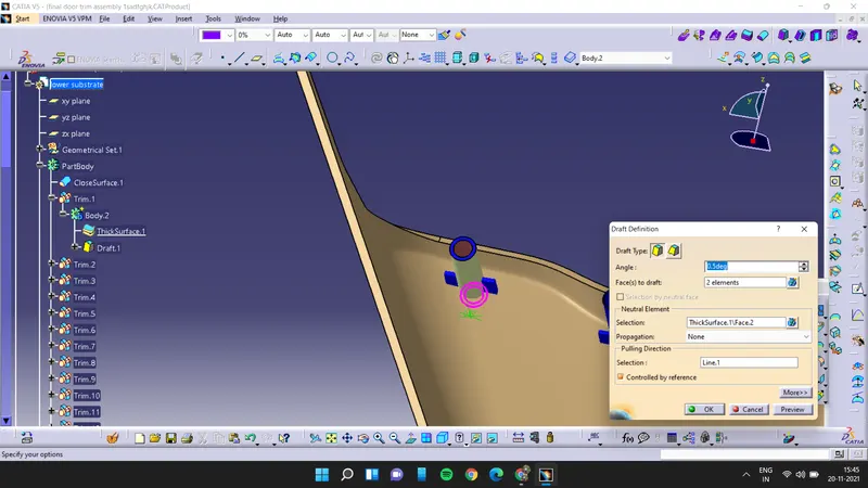
now create the 2 way locators for the heat stakes it will give the strength to the heat stake
for that first create the sketch for the heat stake and the pad it by using thick command and also use the nutral fiber and then use the untrim option to assemble with the lower substarte and also add 0.5deg draft to all the sides and all fillets to it
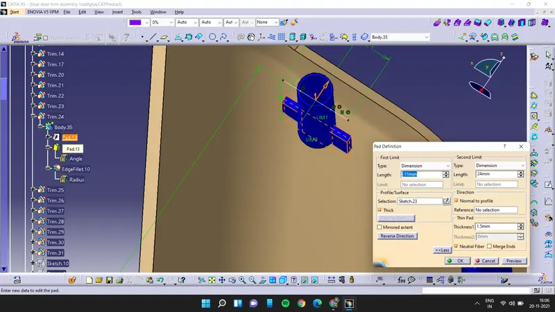
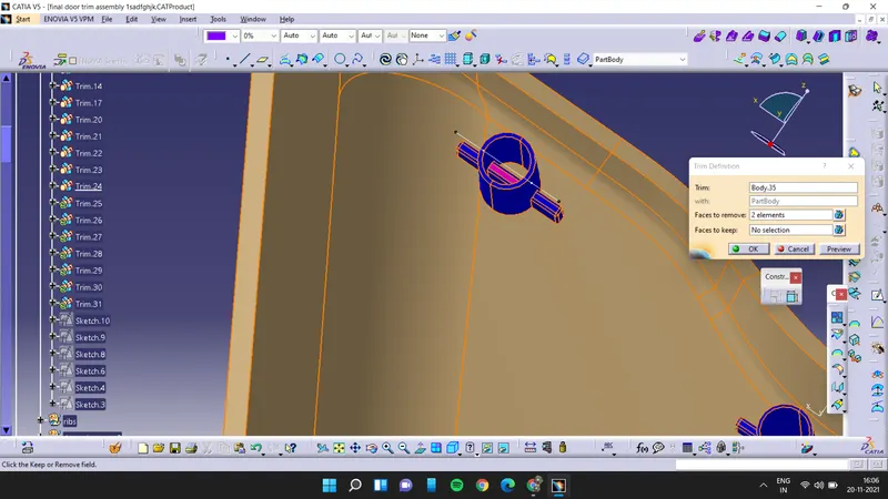
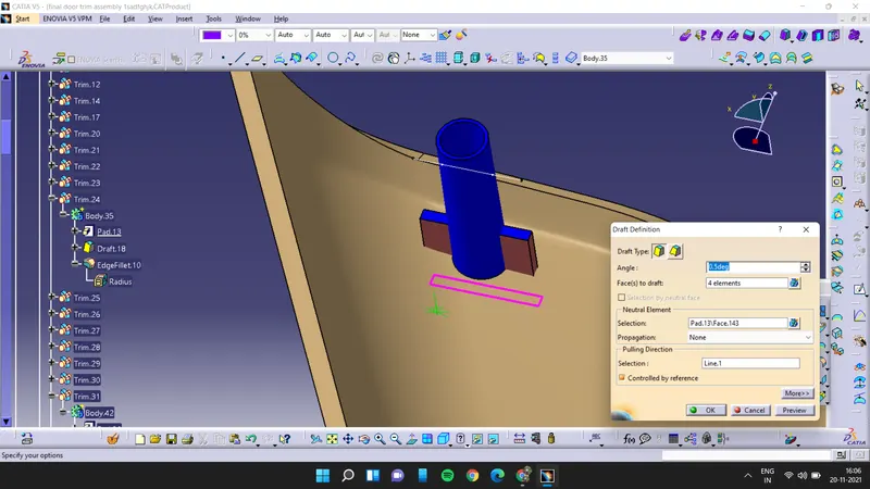
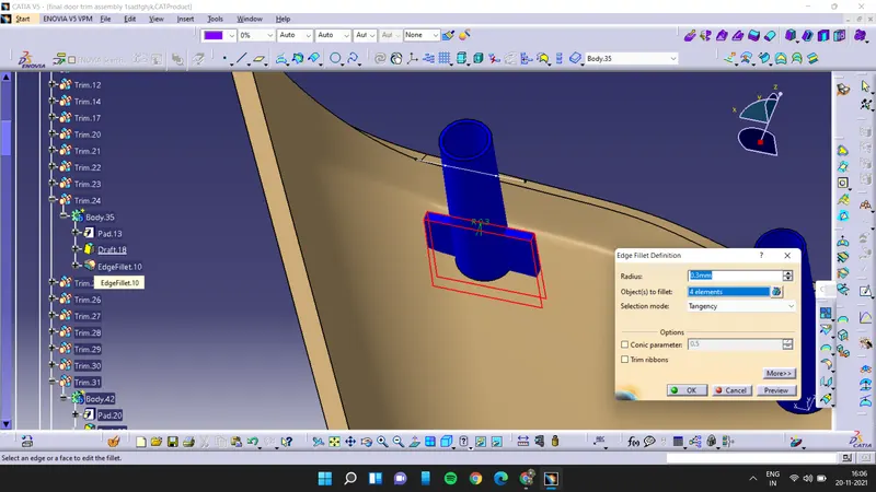
now do the same process for all the heat stakes and the locators for all the flanges now
DOG HOUSE:
draw the sketch and then pad it
and apply the draft for the dog house
use the shell command shell the dog house for 2.5mm and then draw another sketch
and pad it and use remove option to make a cavity at the dog house this is the cavity where our pushpin will be fixed
and all fillets to the dog house where needed
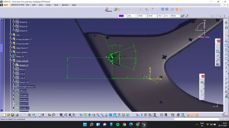
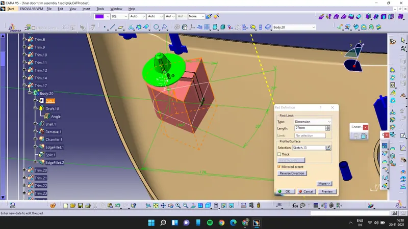
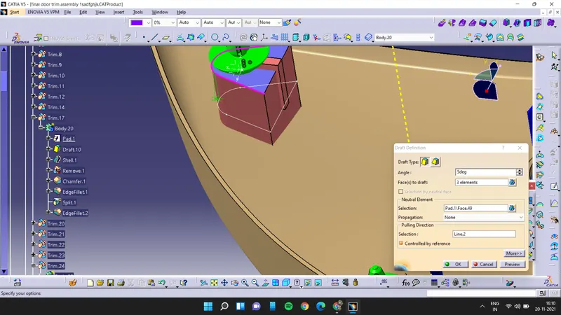
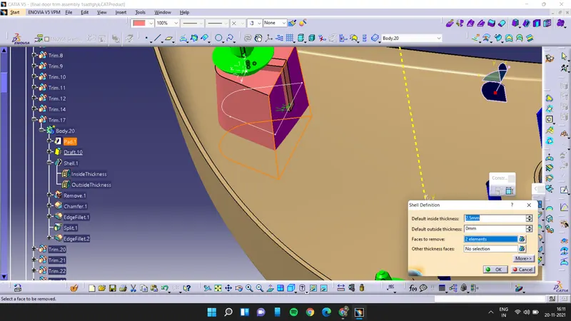
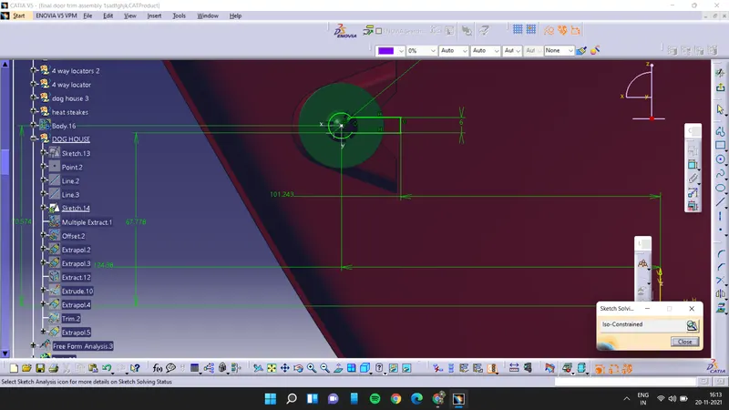
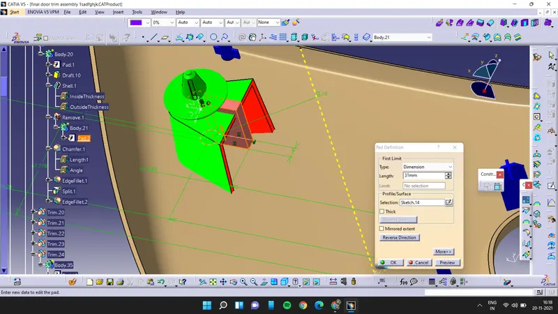
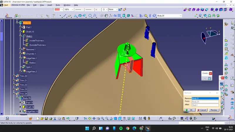
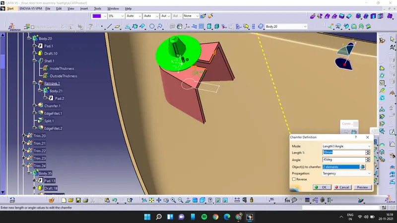
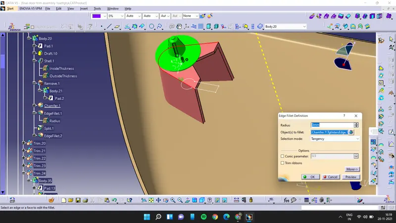
to avoid the sink marks first we have to extract the innser surface of the dog house then we have to offset it inwards for 1mm and then extract the sketch of dog house and extrude it and extratrapolate it and finally trim with the offseted surface and then split it with the dog house and add fillets to it
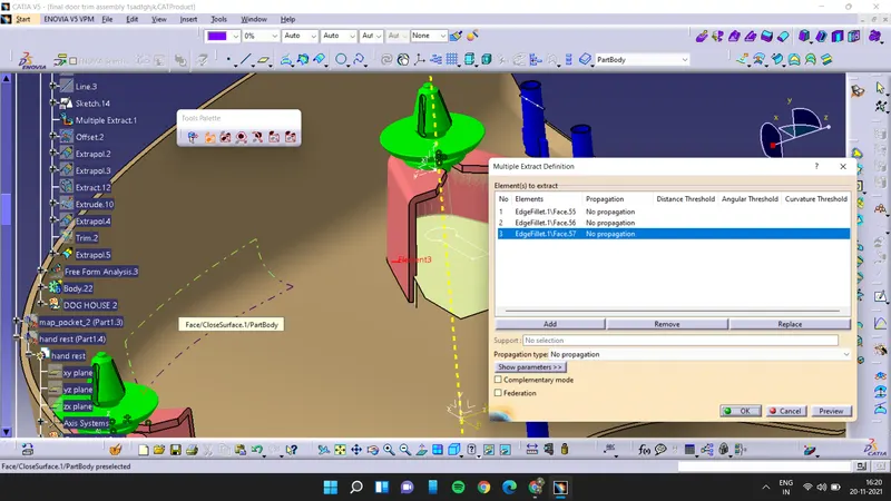
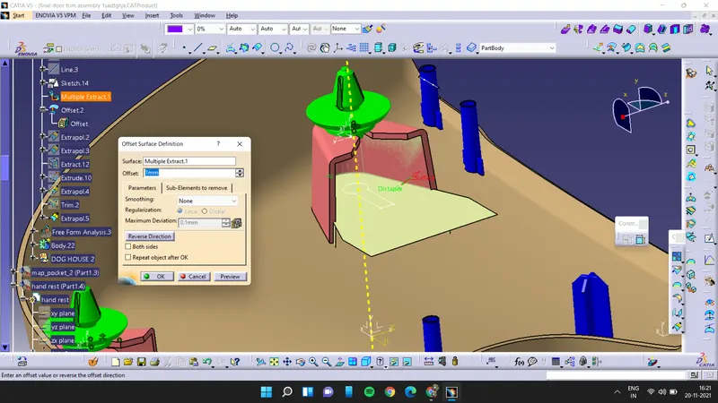
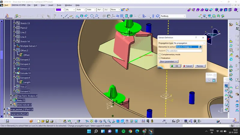
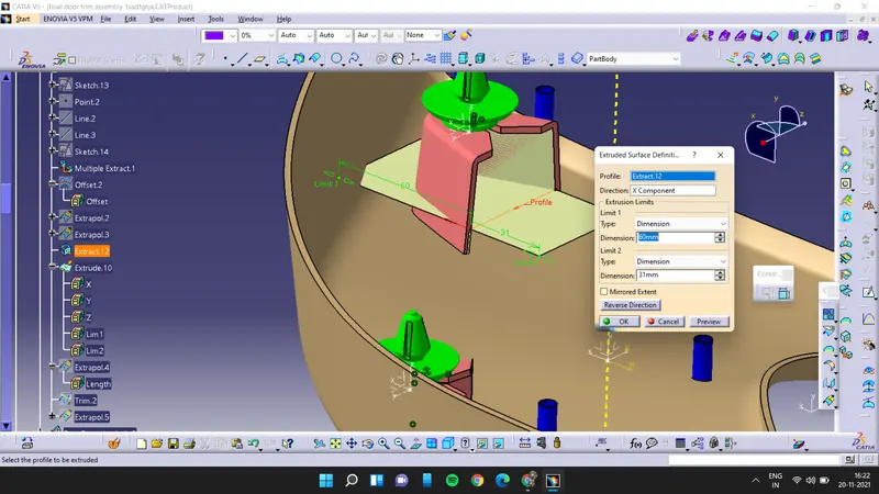
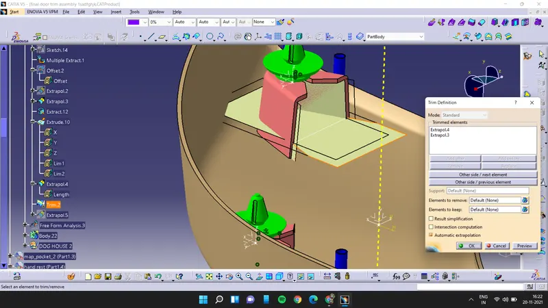
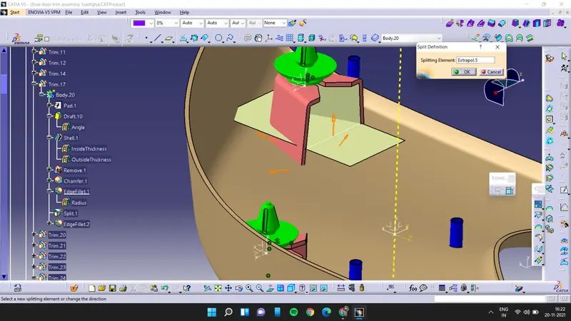
and we have to do the same for rest 2 dog houses
Draft analysis:
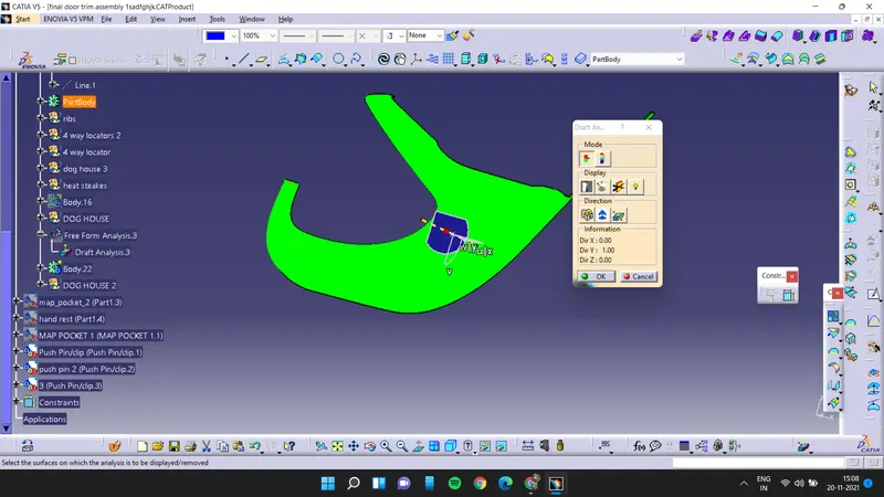
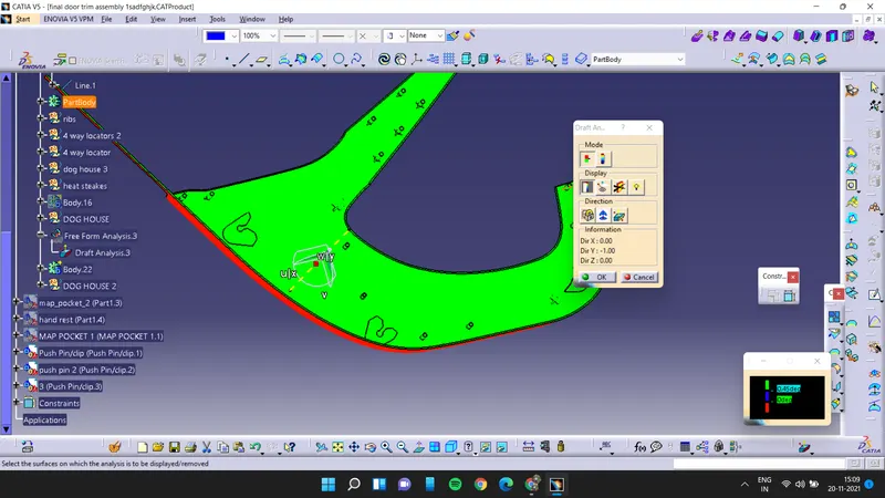
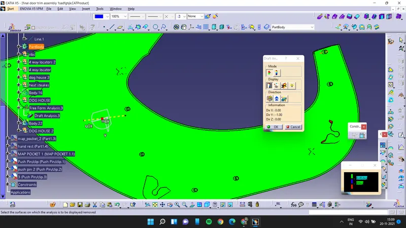
2. Map Pocket 1:
First we have to offset the class A surface for 2.5mm and then extract the edges of class A surface and extrapolate it
now sweep the class A surface
join the swept then class A surface
and now extrapolate the class B surface and then trim the extrapolated surface with class A& class C
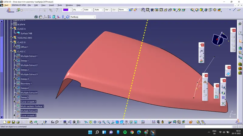
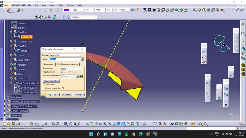
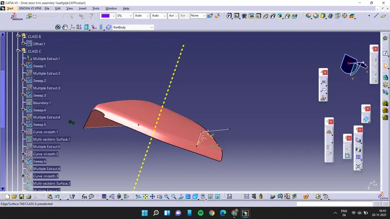
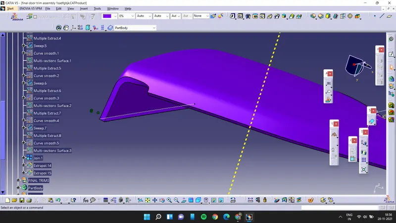
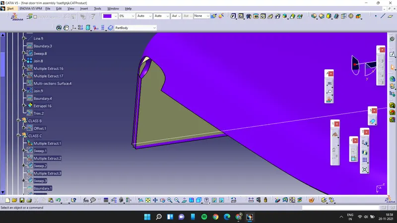
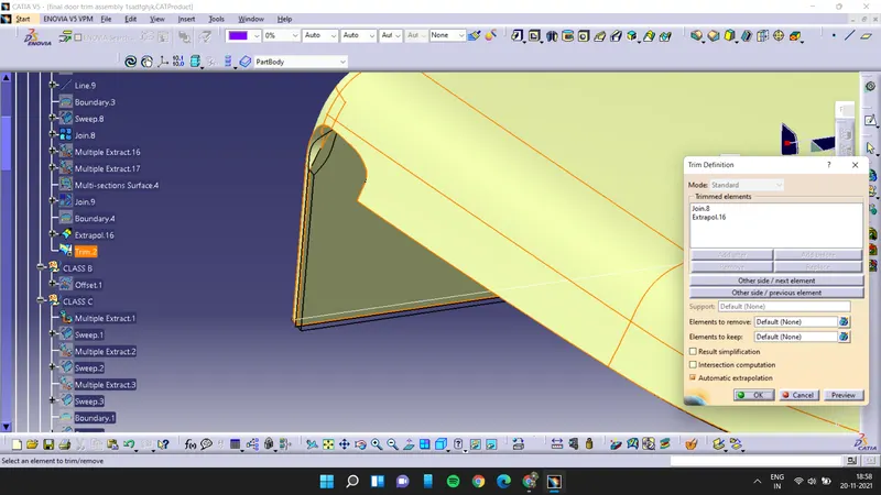
now use thick surface option to create the thick surface and then make flanges for the map pocket
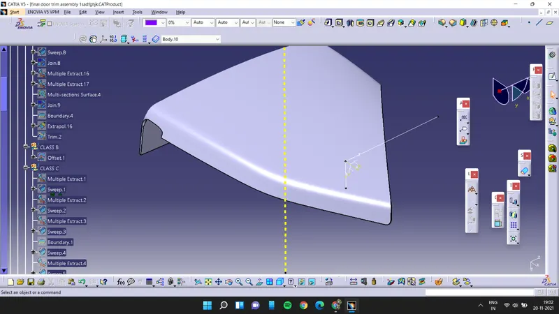
for the flanges first we have to extract the master curves which are provided with the class A surface and then extrude it and we have to offset it for 2.5mm and then close all the edges by sweep command and then we have to trim all the surfaces to make a closed body and then by using close body option we have to make a solid body of it and then it is assembled to the main map pocket after assemblying the flange we have to add fillets to the flange.
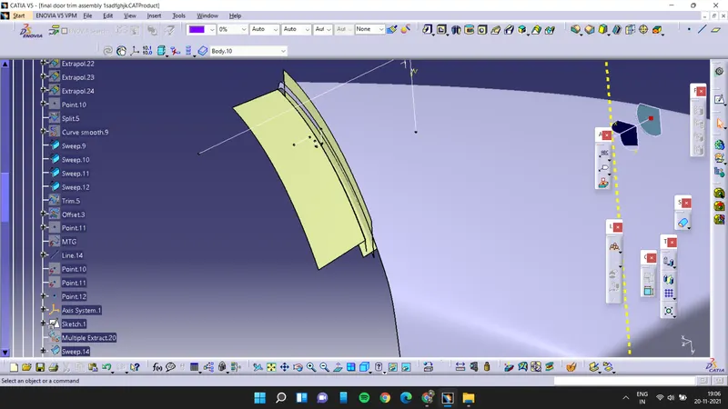
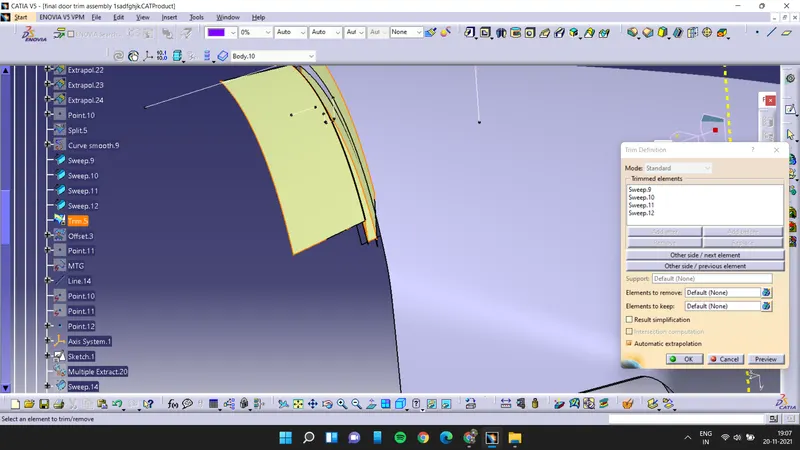
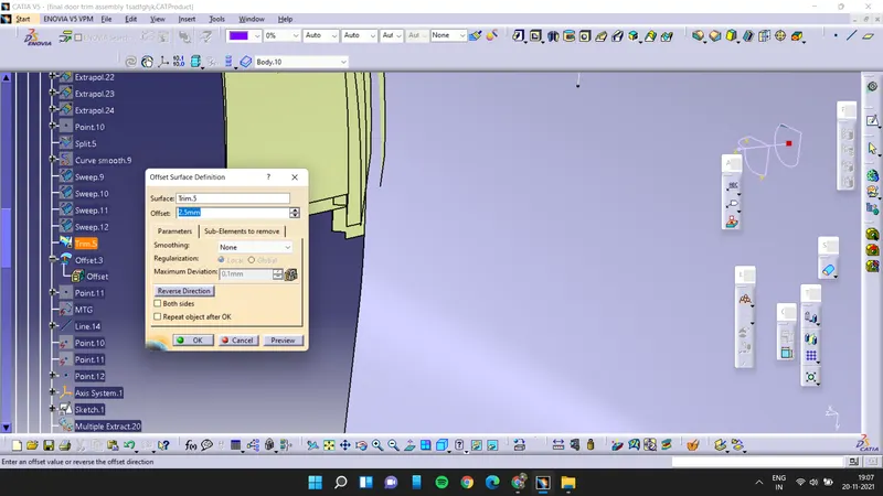
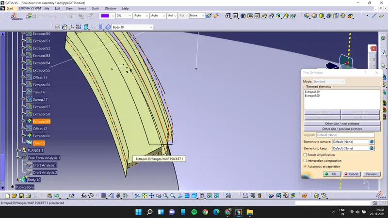
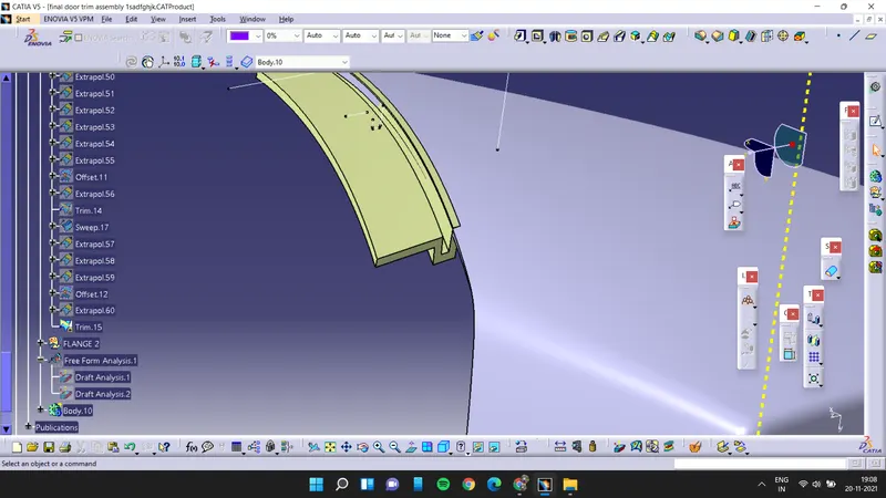
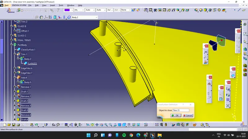
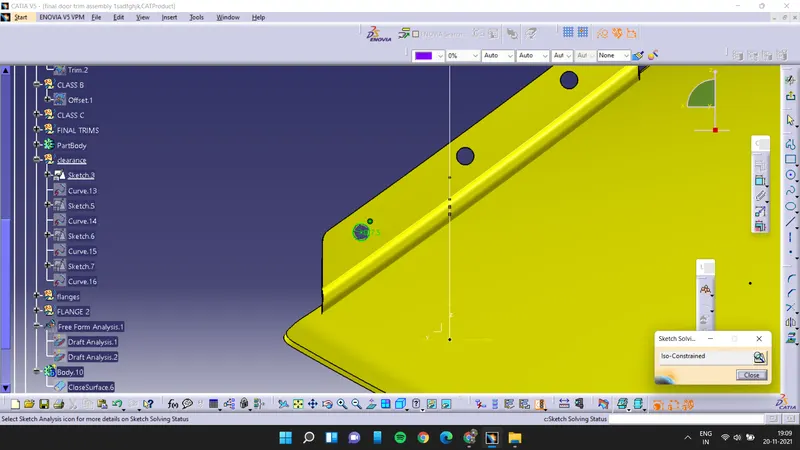
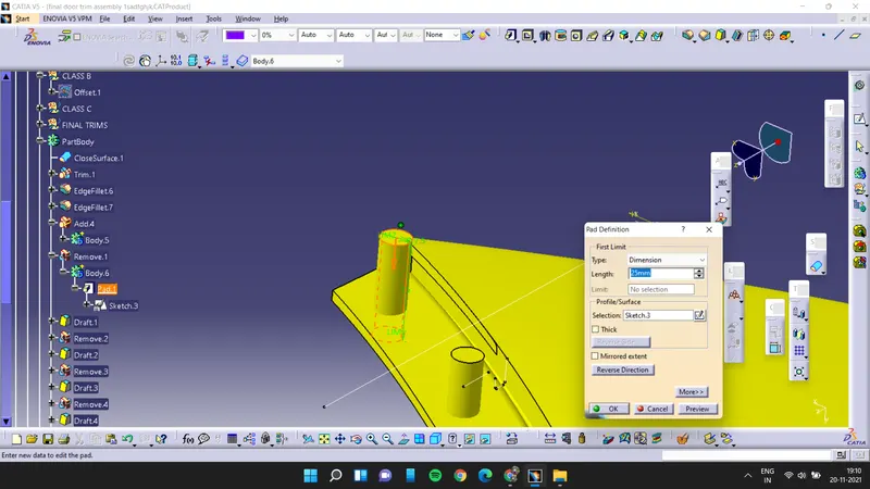
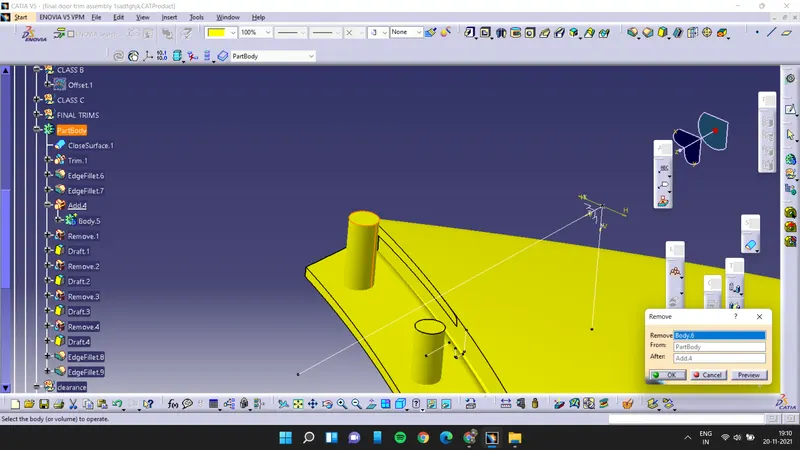
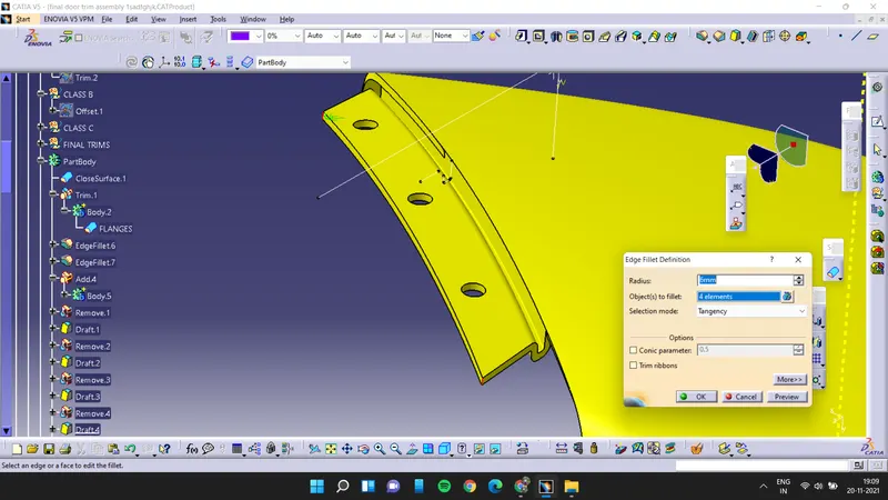
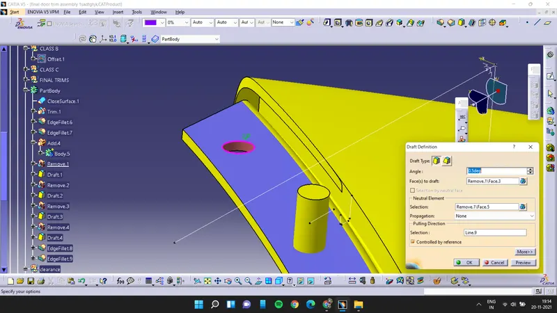
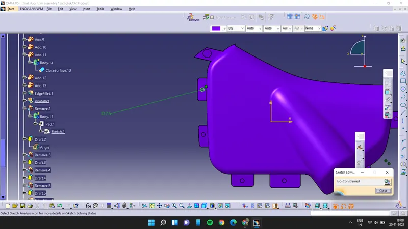
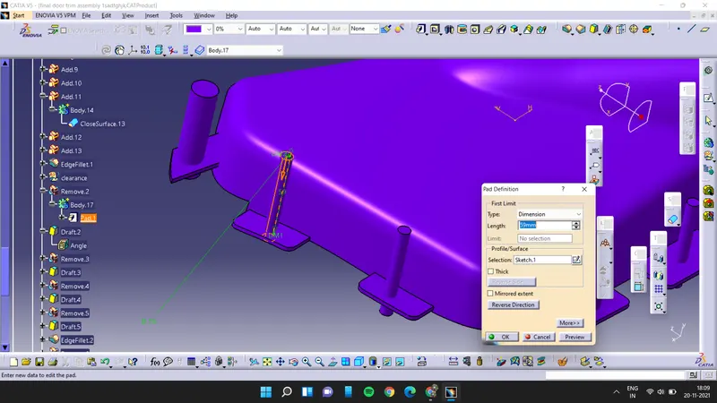
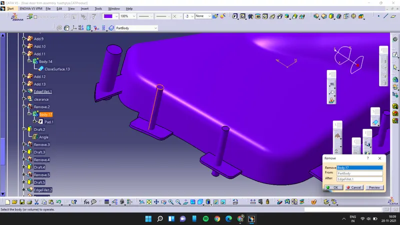
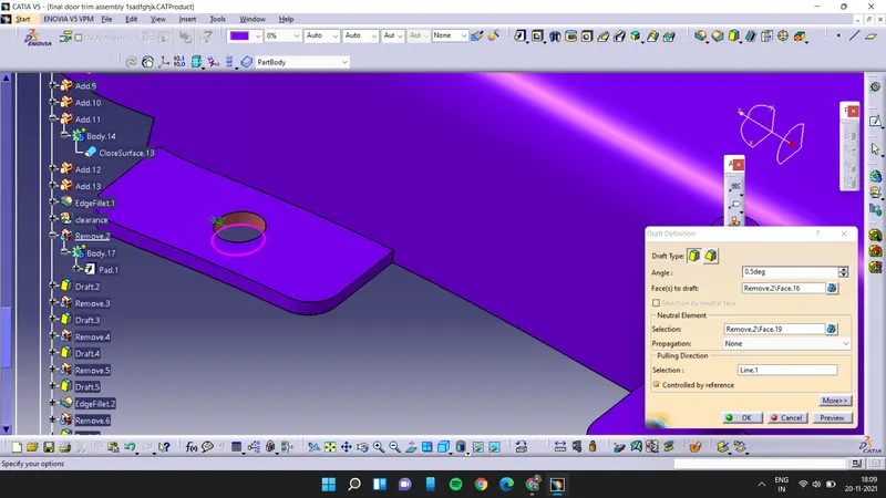
as fillets are applied all we have to do is to create the hole inside the flange for that first we will draw the sketch with respect to the heat stake and then we will pad it and then we will remove the pad body from the main body then we have to apply the draft to the hole.
3. map pocket 2:
First we have to offset the class A surface for 2.5mm and then extract the edges of class A surface and extrapolate it
now sweep the class A surface
join the swept then class A surface
and now extrapolate the class B surface and then trim the extrapolated surface with class A& class C
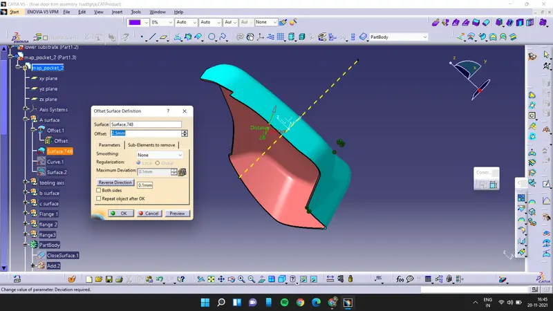
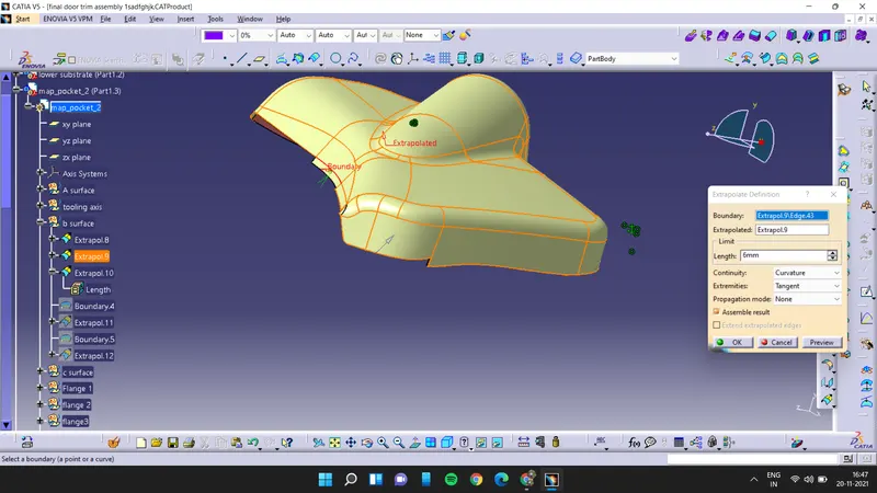
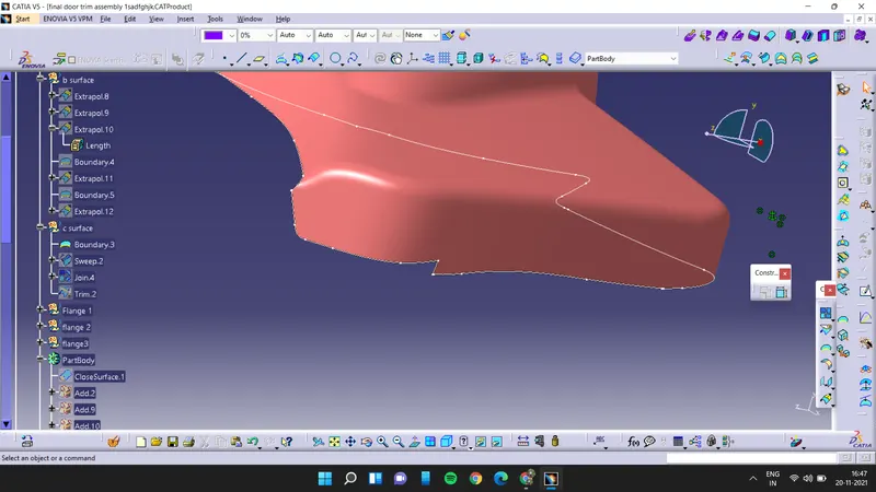
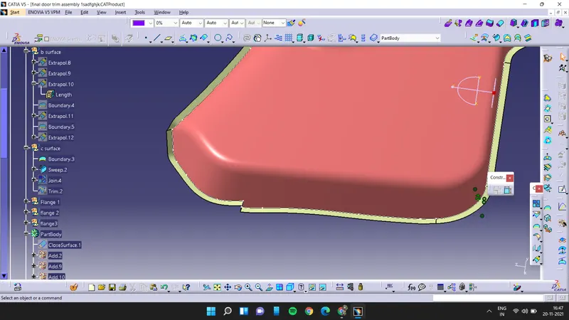
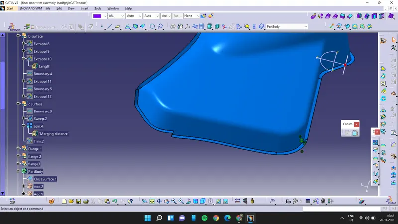
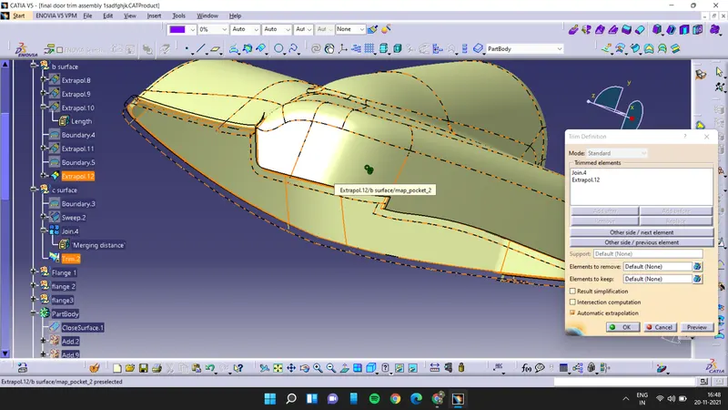
now use thick surface option to create the thick surface and then make flanges for the map pocket
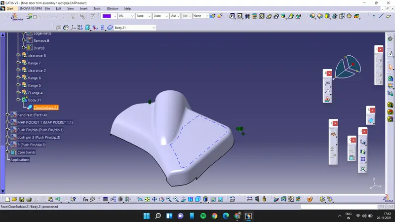
for the flanges first we have to extract the edges and then extrude it and we have to offset it for 2.5mm and then close all the edges by sweep command and then we have to trim all the surfaces to make a closed body and then by using close body option we have to make a solid body of it and then it is assembled to the main map pocket after assemblying the flange we have to add fillets to the flange.
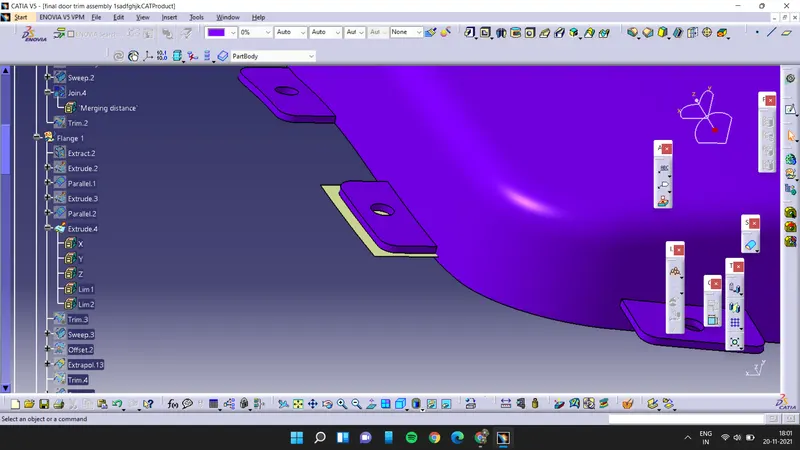
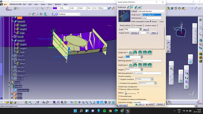
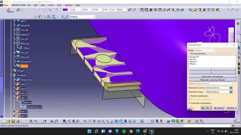
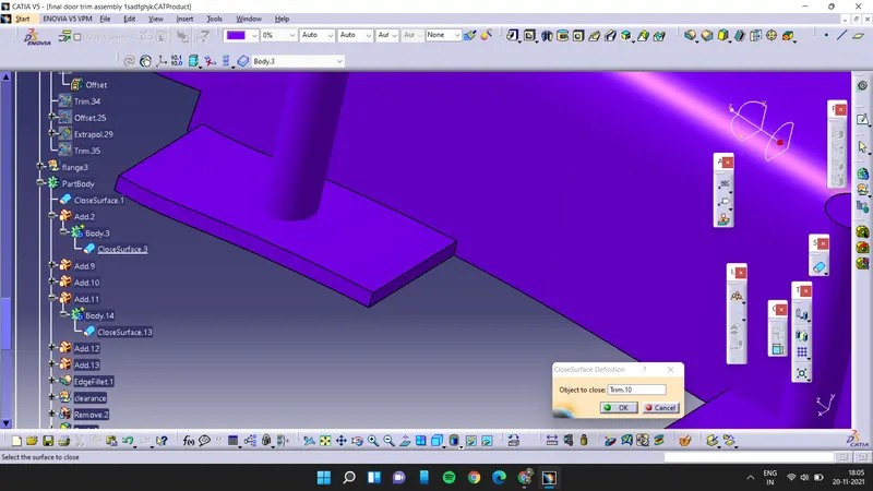
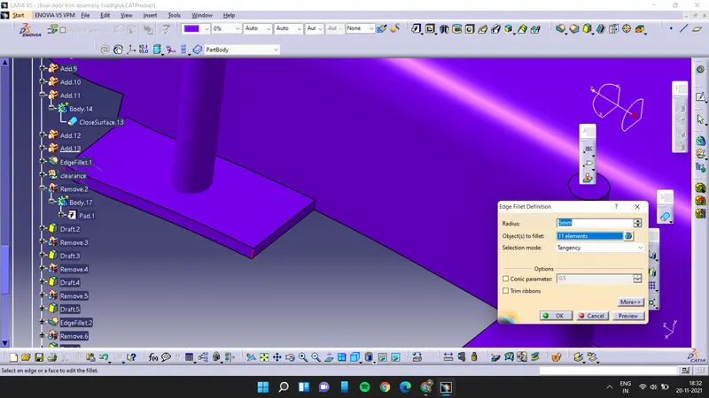
as fillets are applied all we have to do is to create the hole inside the flange for that first we will draw the sketch with respect to the heat stake and then we will pad it and then we will remove the pad body from the main body then we have to apply the draft to the hole.
4. Hand Rest:
First we have to offset the class A surface for 2.5mm and if there is any improper surface is coming then make it complete first then extract the edges of class A surface and extrapolate it
now sweep the class A surface
join the swept then class A surface
and now extrapolate the class B surface and then trim the extrapolated surface with class A& class C
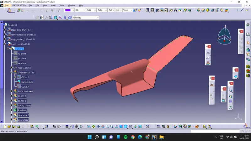
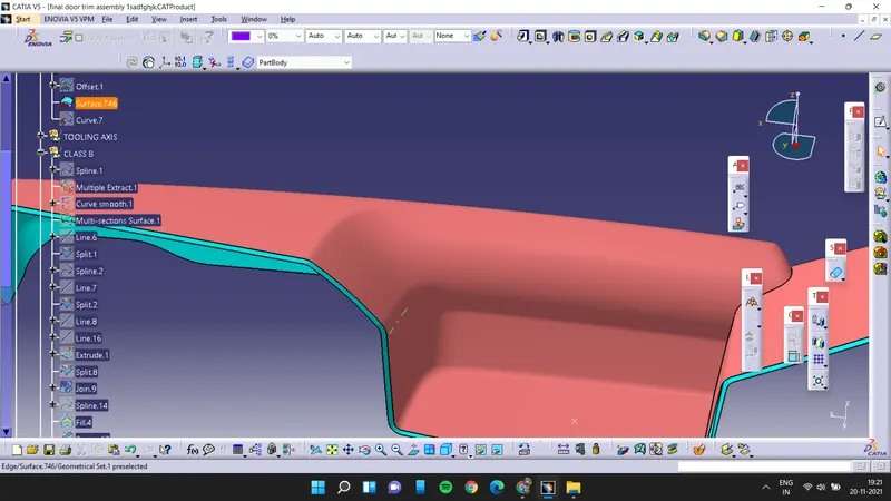
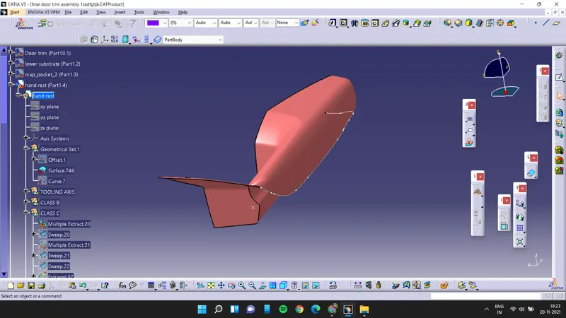
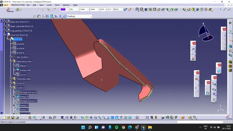
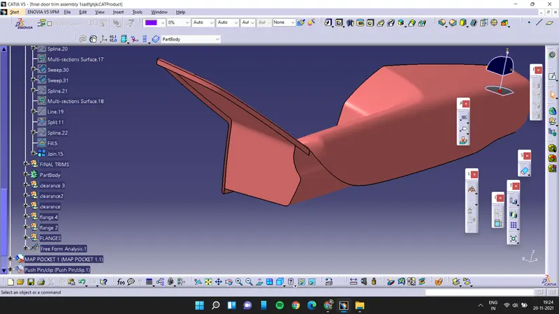
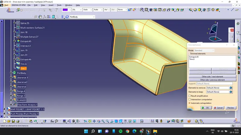
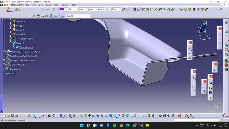
for the flanges first we have to extract the master curves which are provided with the class A surface and then extrude it and we have to offset it for 2.5mm and then close all the edges by sweep command and then we have to trim all the surfaces to make a closed body and then by using close body option we have to make a solid body of it and then it is assembled to the main map pocket after assemblying the flange we have to add fillets to the flange.
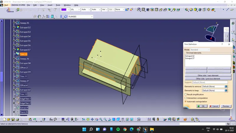
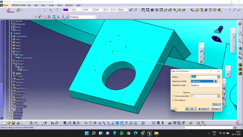
as fillets are applied all we have to do is to create the hole inside the flange for that first we will draw the sketch with respect to the heat stake and then we will pad it and then we will remove the pad body from the main body then we have to apply the draft to the hole.
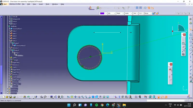
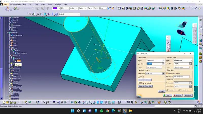
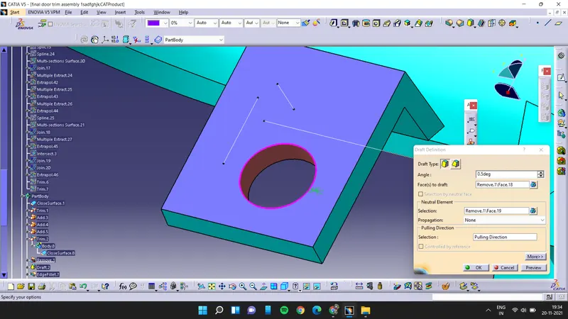
after completing all the part fix the lower substrate and then insert the pushpin assemble on the dog house by using coincidence constaint