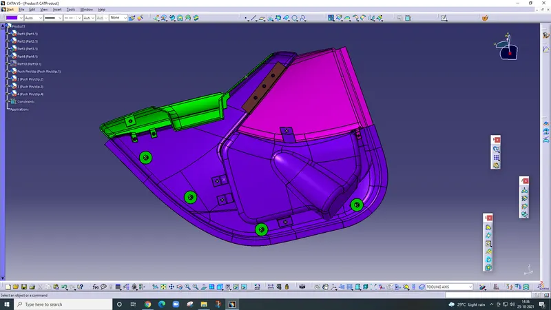
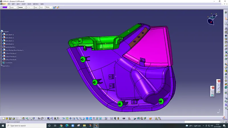
Week 11 - Final project
Aim - To the development of a Door Trim panel.
Introduction - In the project provides 4 components Claas A Surface ( Door rest arm and switch bezel, upper mop packet, lower mop packet, lower subtract) then create B surface and C surface. The door panel is the interface between the interior of the car and the inner workings of the door. Generally, the door panel is divided into parts for easy designing like the armrest, map pocket, lower substrate. These require one of the toughest requirements among the interior parts of the car. This should be designed to withstand the load while being less than 2mm in thickness and also to protect the occupants during collisions.
Methodology -
1) Tooling axis Creation.
2) Create the B surface.
3) Creation of C surface.
4) Create a solid body.
5) Adding Engineering feature.
6) Draft analysis of all components.
Class A surface door Trim panel
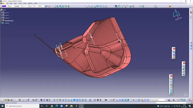
Firstly separate the door rest arm then work on it and Create b surface and c surface.
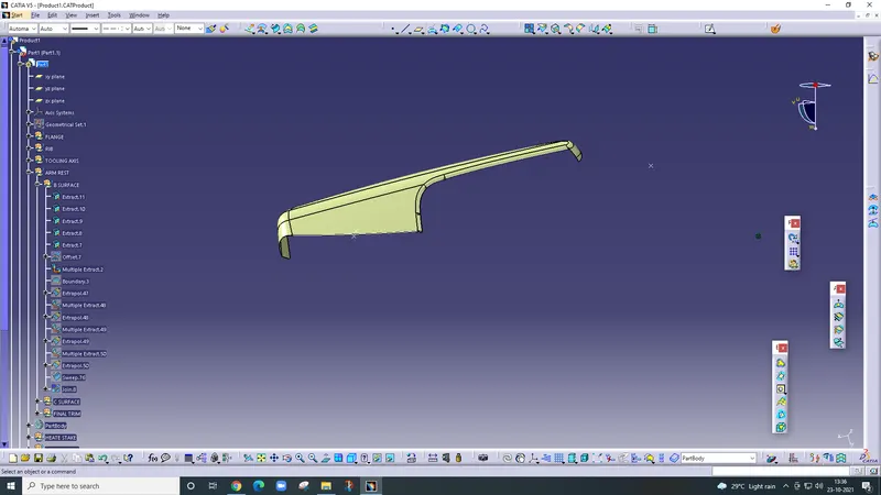
tooling axis of rest arm
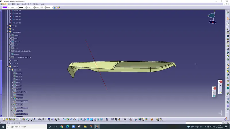
Offset the class A surface up to 2.5mm in the down direction.
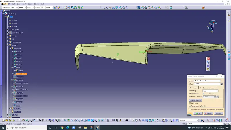
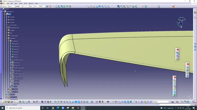
Then taking Class A surface, to create c surface by using sweep, multi-sectional command.
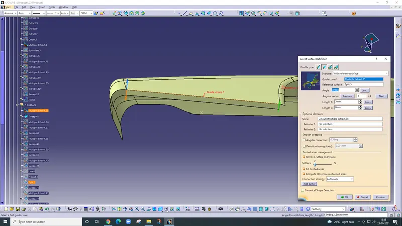
Here small defect, then draw a line then use the projection command after that split the defect.
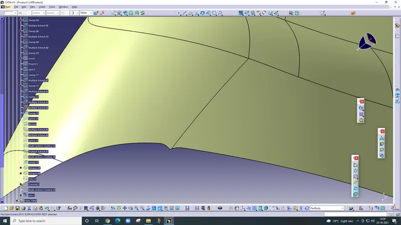
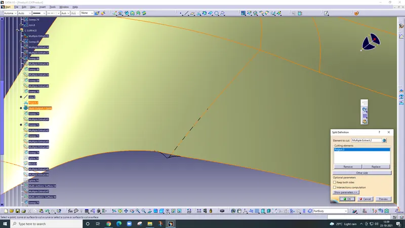
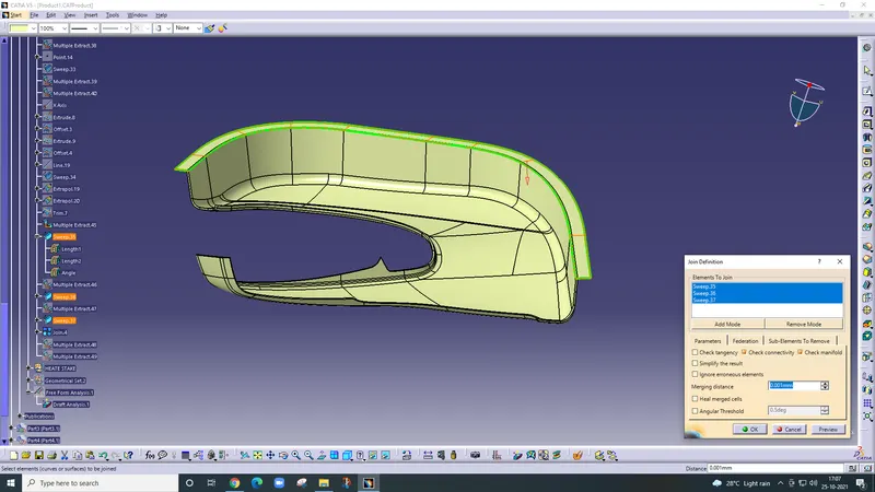
after completing the sweep then use the join command and join the class A surface and create c surface.
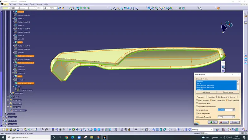
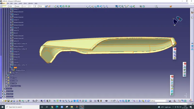
B Surface
Extrapolate the B surface and then join the B surface.
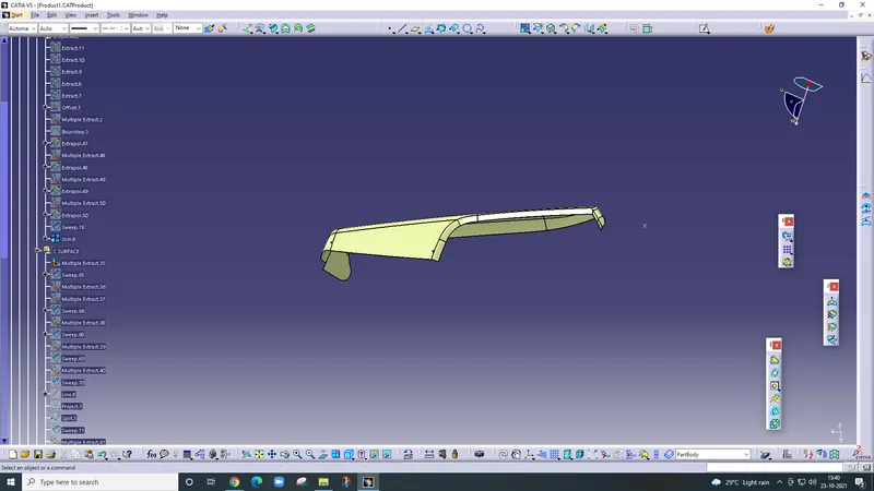
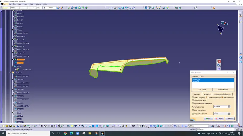
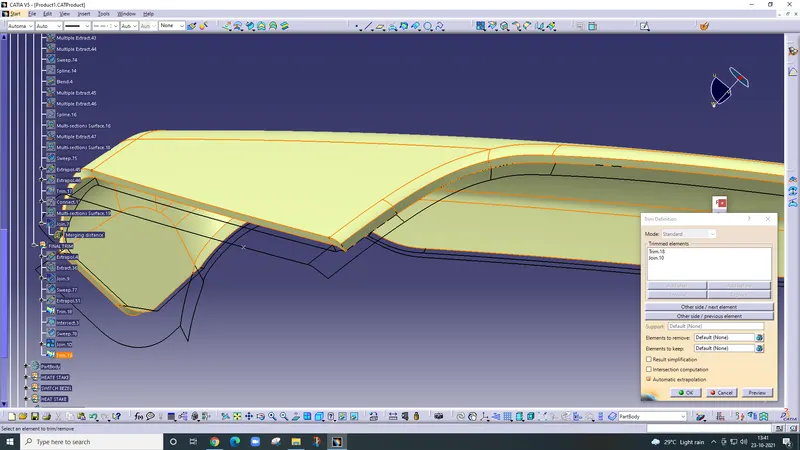
then create the B surface and C surface then use trim command and create the final body.
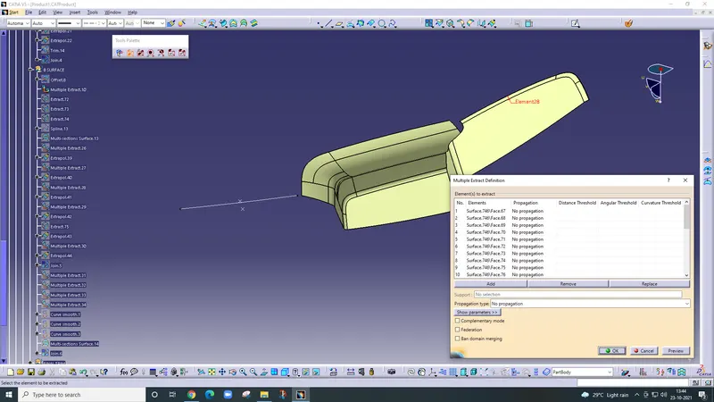
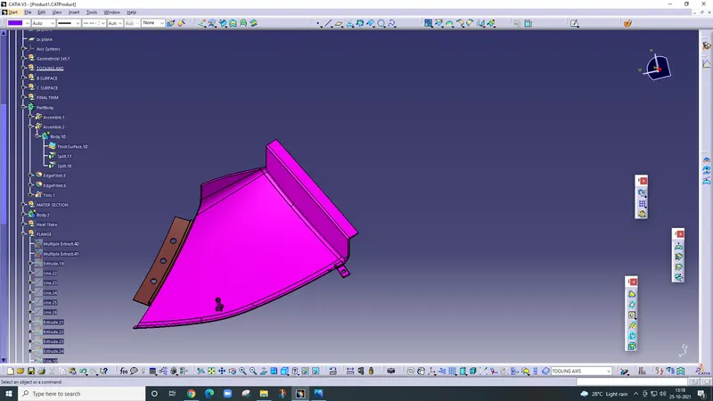
Create the switch bezel. Firstly extract the component using multiple extract commands and separate the component.
tooling axis on X direction and Y direction.
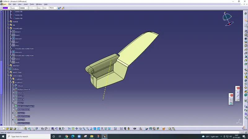
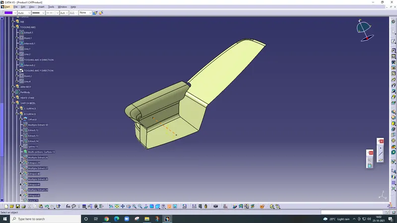
offset the switch bezel in the down direction up to 2.5mm.
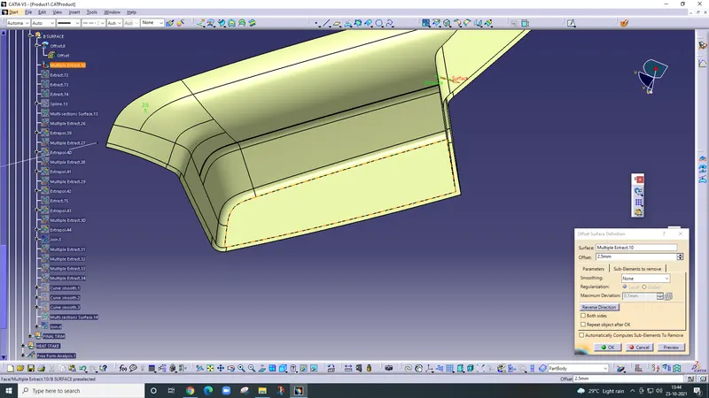
then small patches are detected then multisectional commands are used and fill the patch.
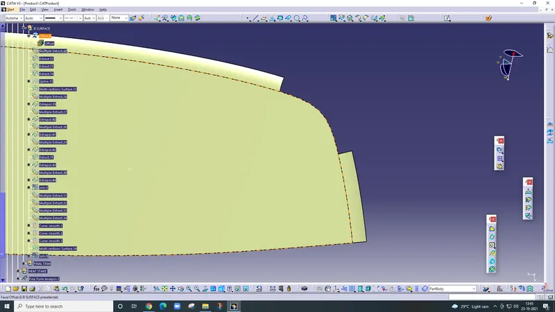
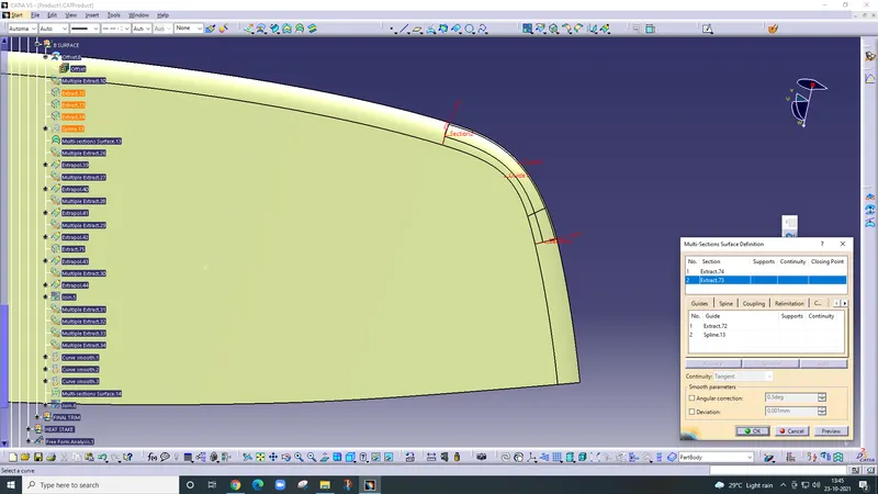
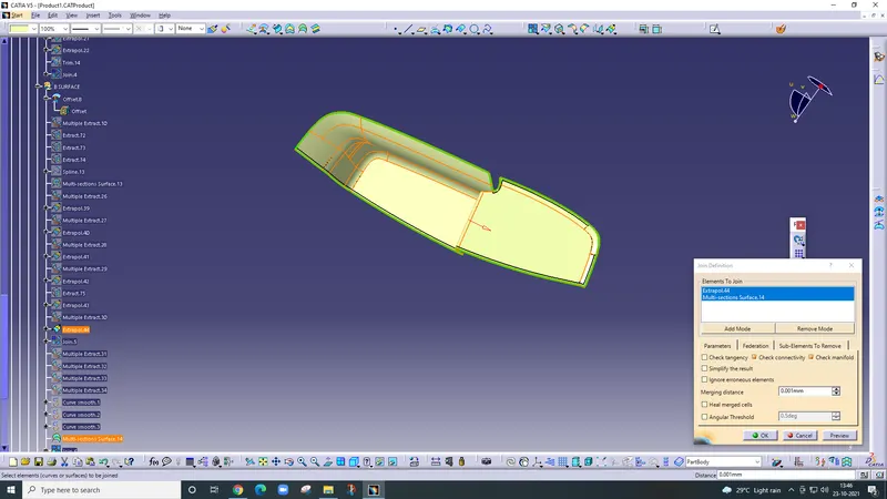
Create C surface using Class A surface, using sweep command and multisectional command.
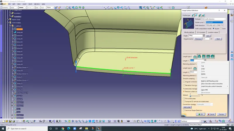
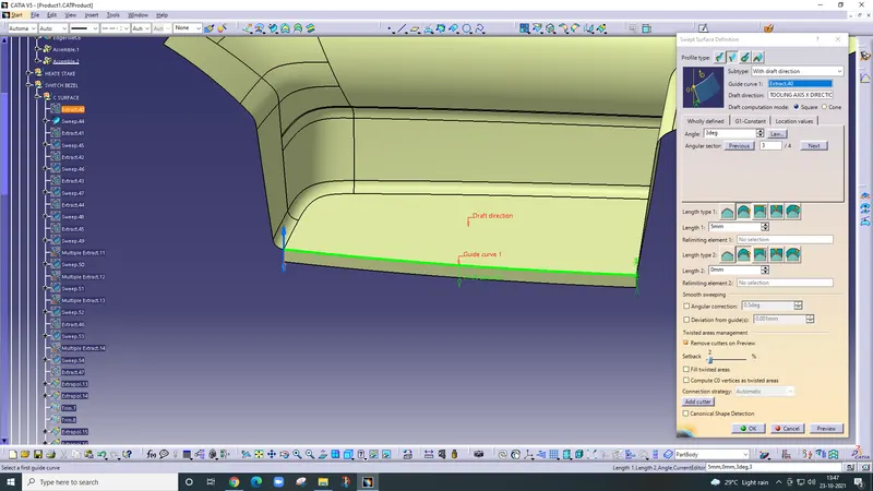
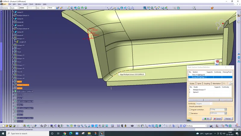
after that join class, A Surface and C surface using the join command
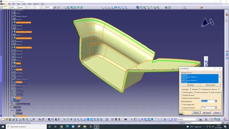
After creating the B surface and C surface then trim both surfaces using the trim command.
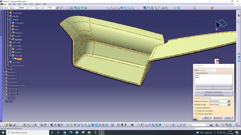
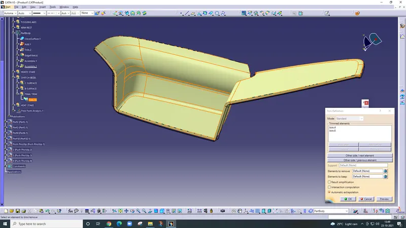
after that creating a solid body then add flanges.
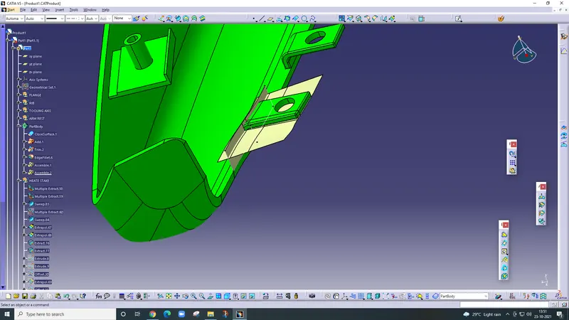
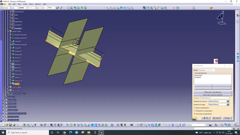
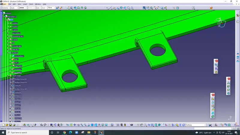
The rib is added to the inclined area.
General design rules for ribs are:
- Min draft per side is 0.5deg.
- The thickness of ribs should be 40% of nominal thickness.
- Height <=5 times the wall thickness.
- Min thickness at the tip is 0.75mm
- Fillet is 0.25m 6. Rib root thickness should be 30% of the wall thickness.
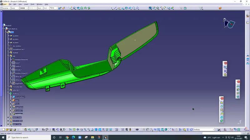
Firstly draw the sketch then extrude and then thick up to 1mm using the thick surface command.
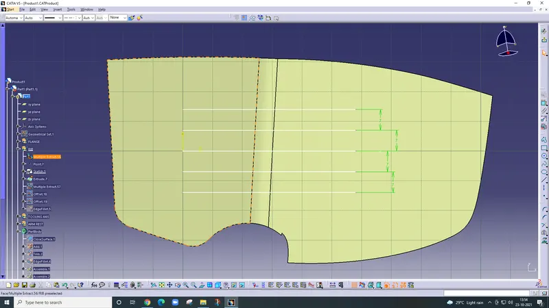
trim the extrude part at 12mm height
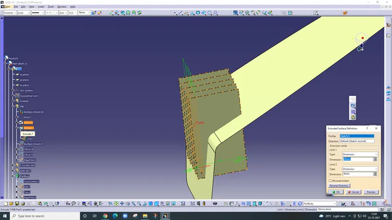
then untrim the extra part.
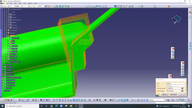
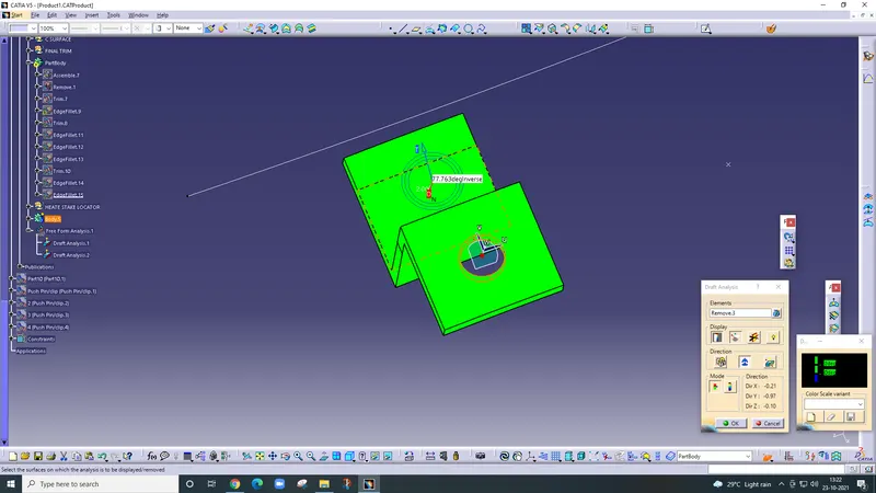
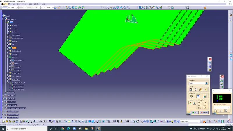
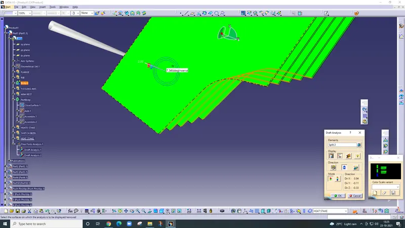
draft analysis of flanges and ribs.
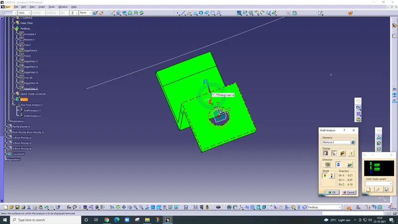
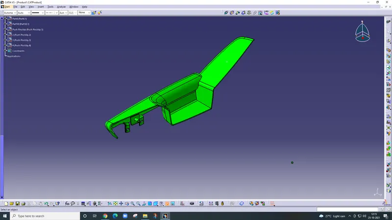
Final component.
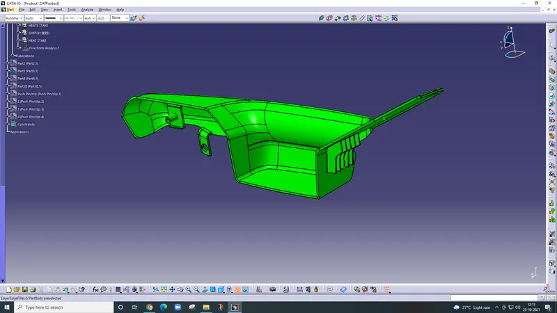
Upper Mop pocket -
Create the B surface and C surface on the Mop pocket
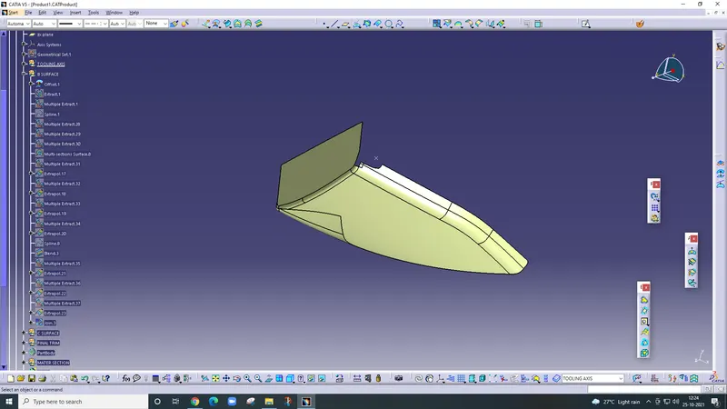
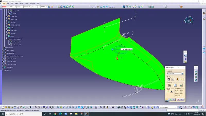
Draft analysis
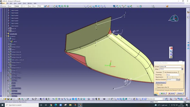
offset the surface up to 2.5mm.
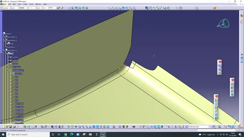
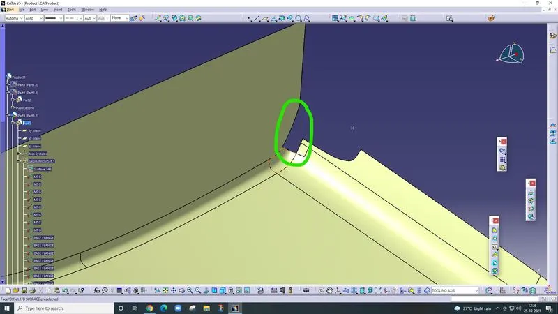
a small patch is detected fill the patch using the multi-sectional command.
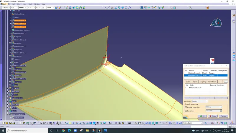
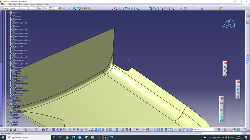
Extrapolated the surface b
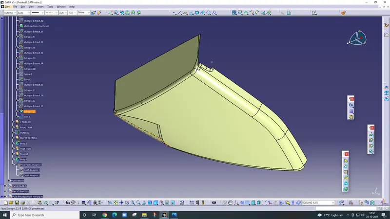
then join the b surface.
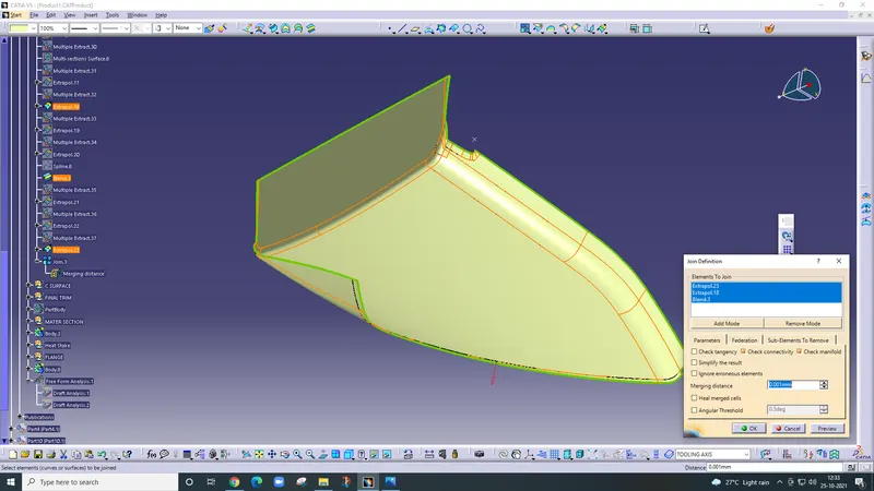
creating the c surface using the class-A surface.
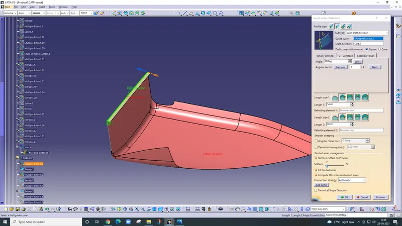
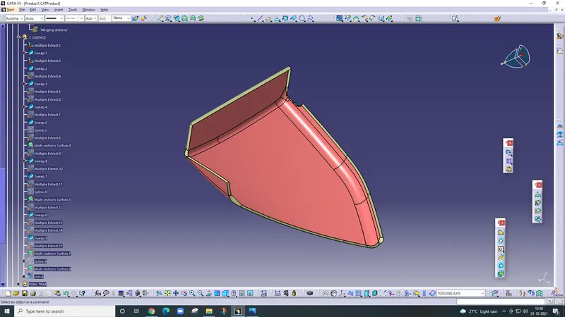
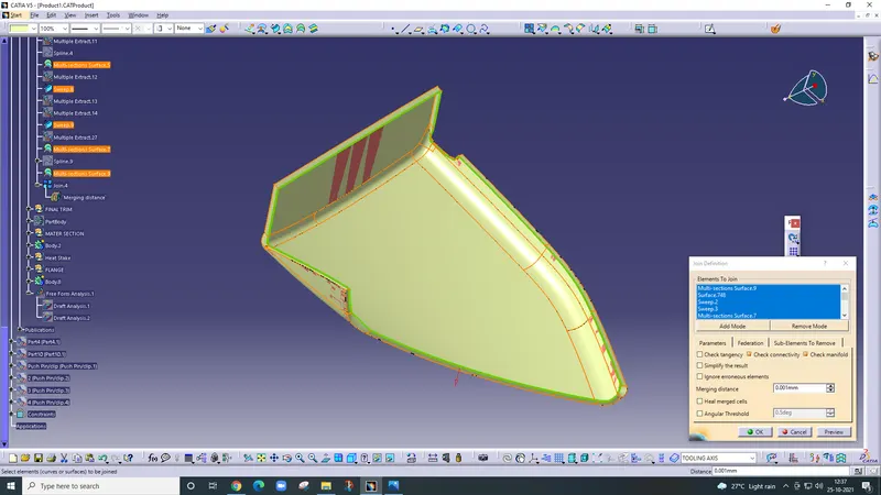
join the class A surface and c surface.
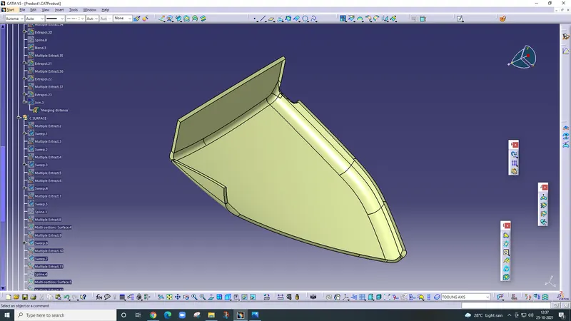
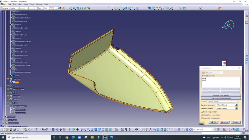
Trim the b surface and c surface.
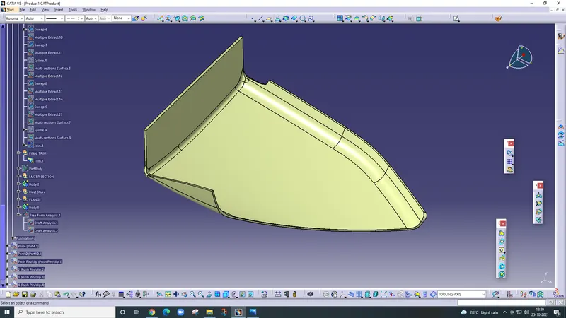
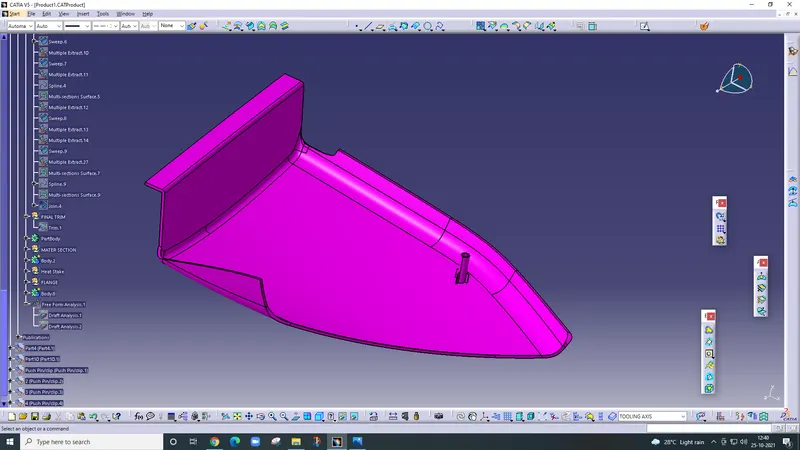
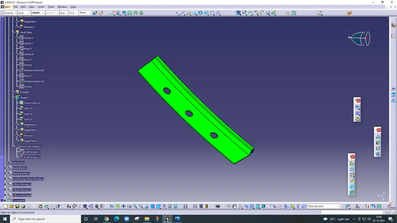
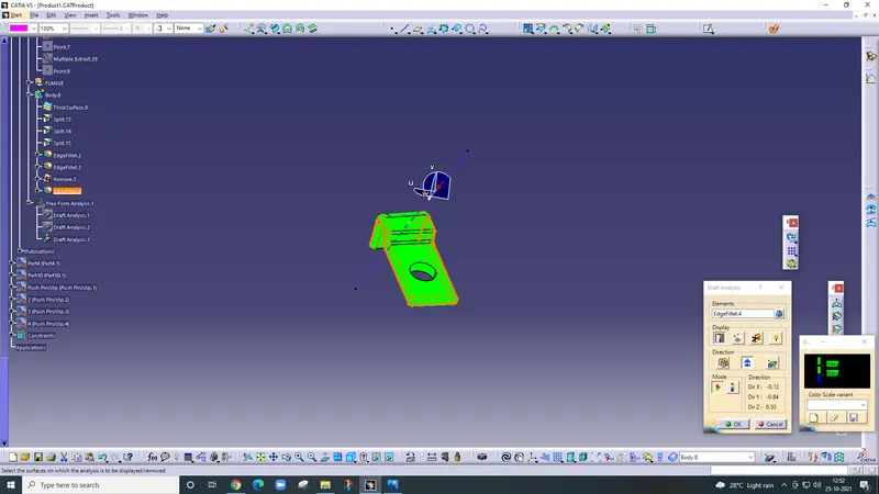
Adding flanges
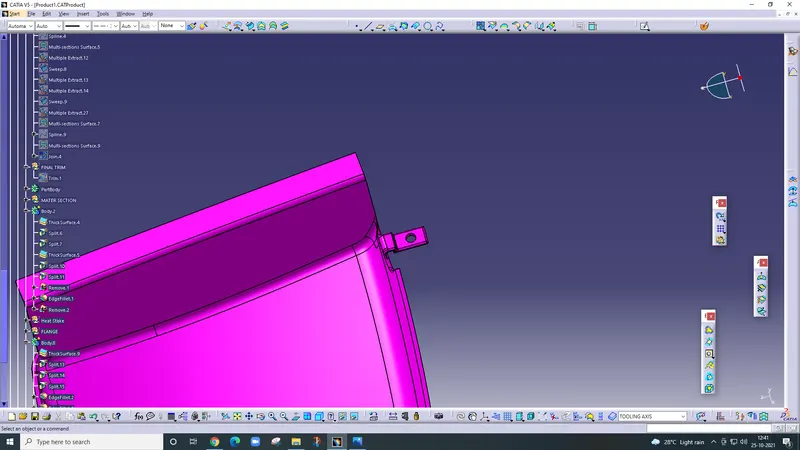
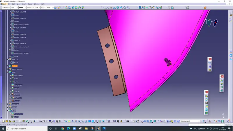
draft analysis of flanges
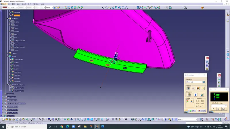
Adding flang then thick up to 2.5mm then the extra flange is split into both sides.
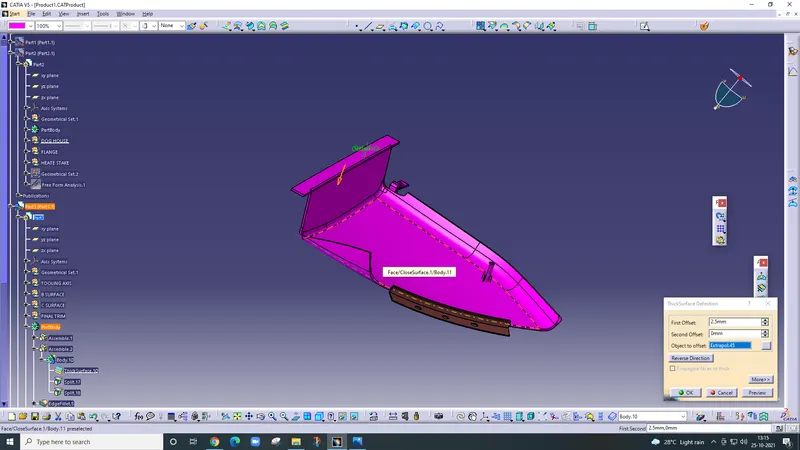
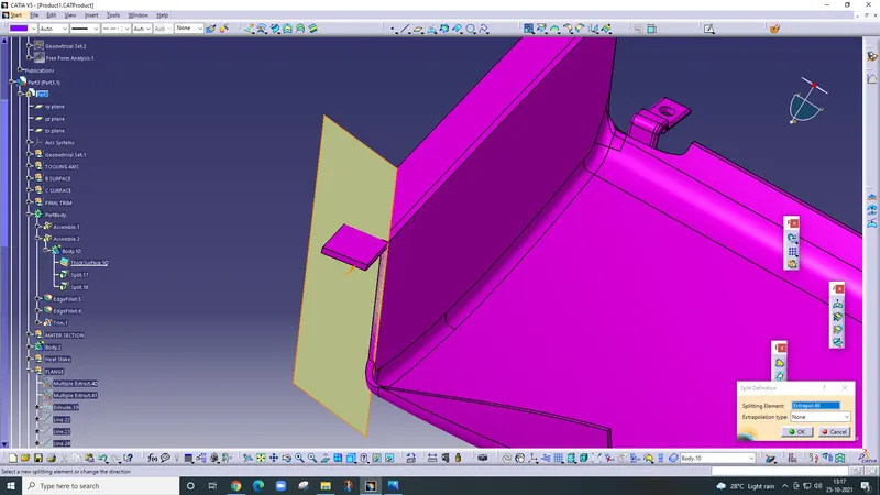
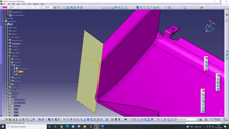
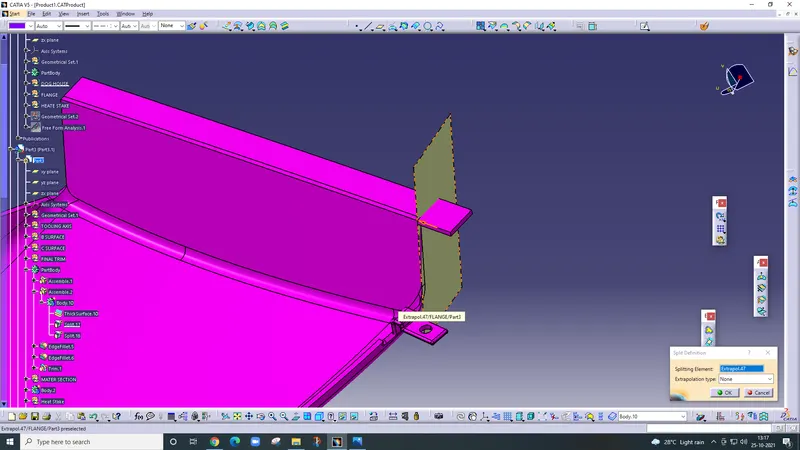
Draft analysis of added flange
Lower mop pocket
Firstly offset the lower mop pocket 2.5mm.
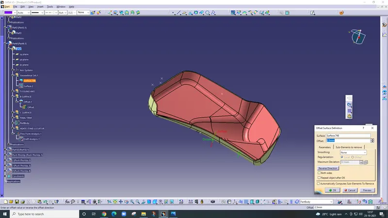
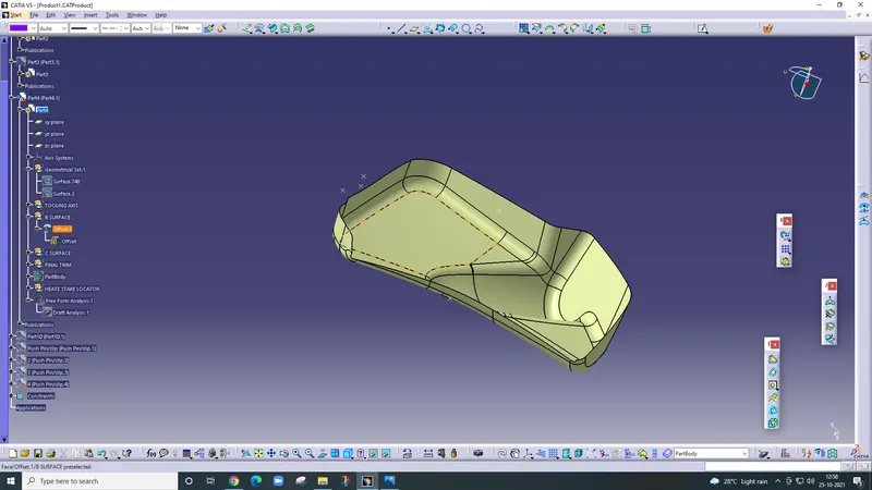
create the c surface using the class-A surface.
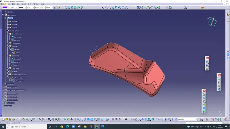
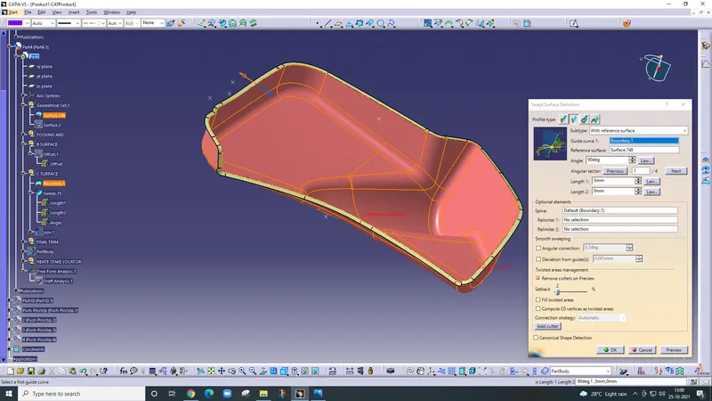
Using the sweep command create the c surface.
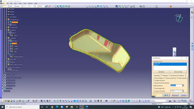
join the Class A surface and c surface.
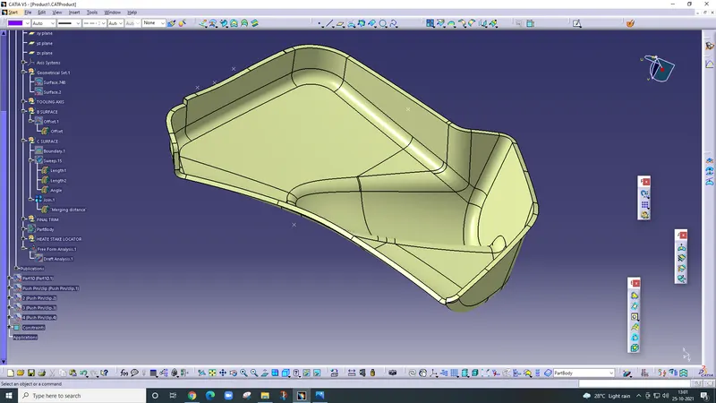
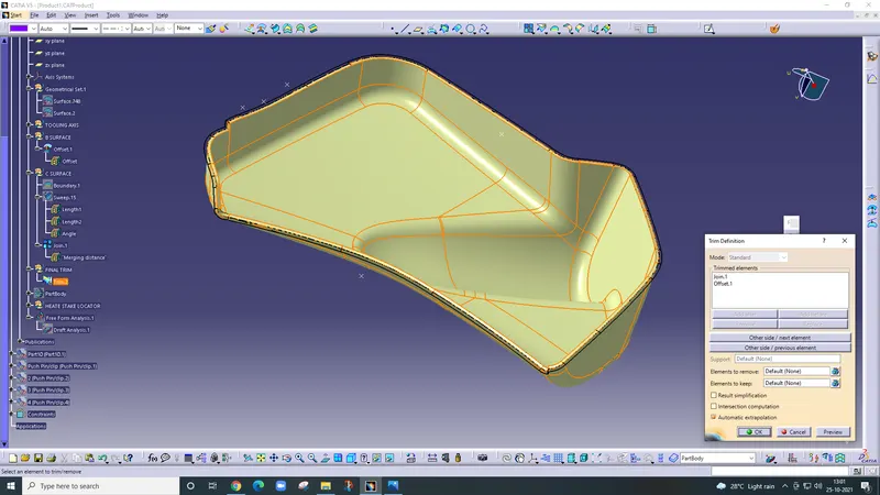
trim the B surface and c surface using the trim command and get the final body.
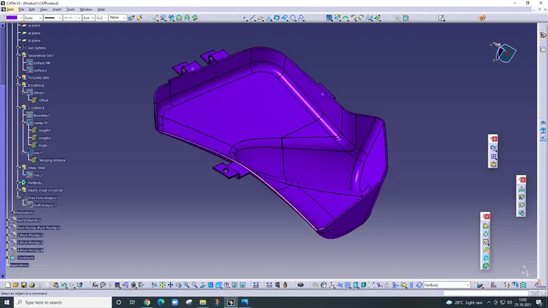
Added the flanges
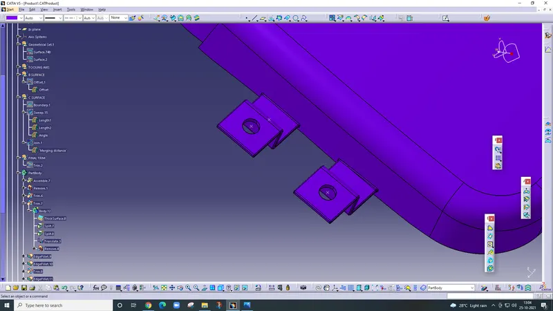
Draft analysis on lowe mop pocket.
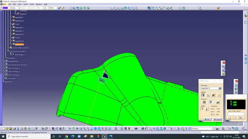
Lower substrate
Class A surface of lower substrate
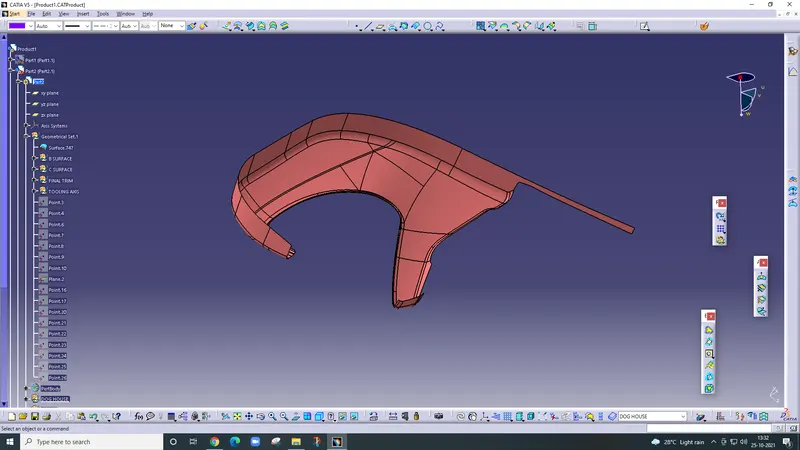
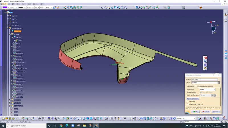
offset class A surface up to 2mm.
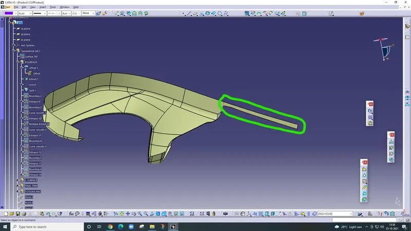
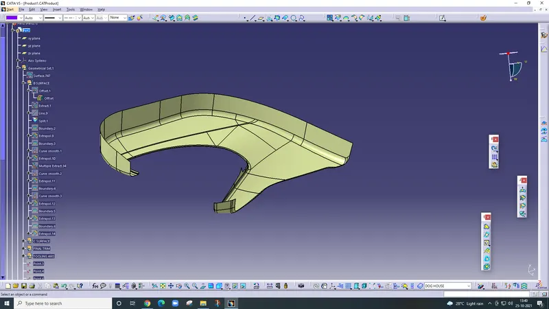
Extra material is removed using the split command.
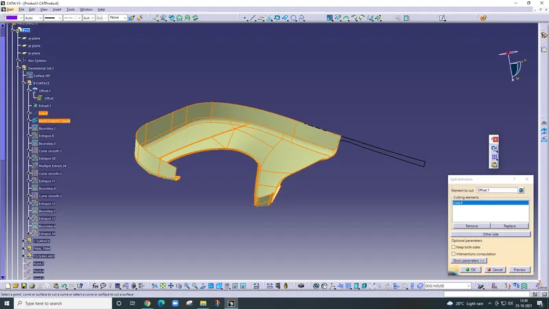
B surface
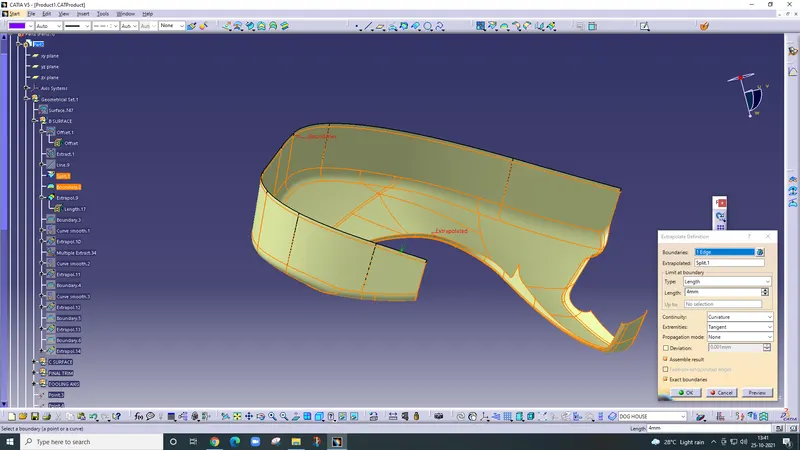
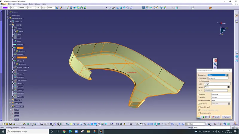
Extrapolate the B surface
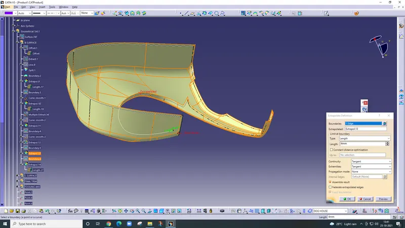
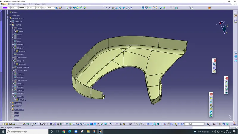
create the c surface of the lower substrate.
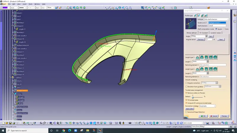
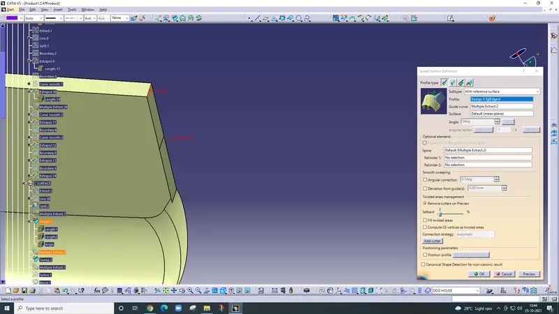
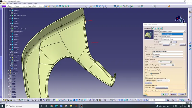
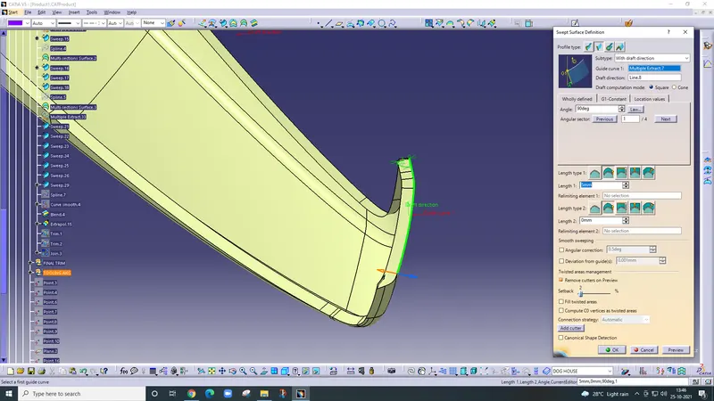
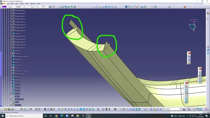
the gap between two flanges then extrapolate the flanges and then use trim command.
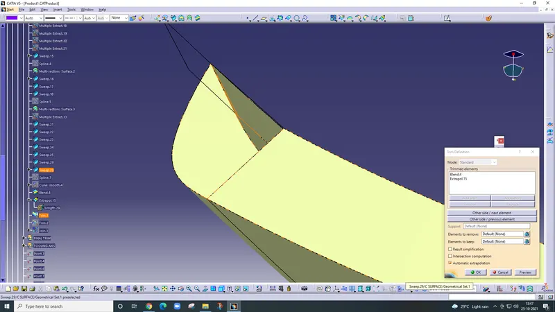
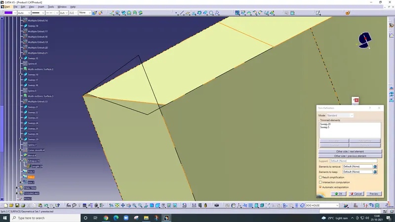
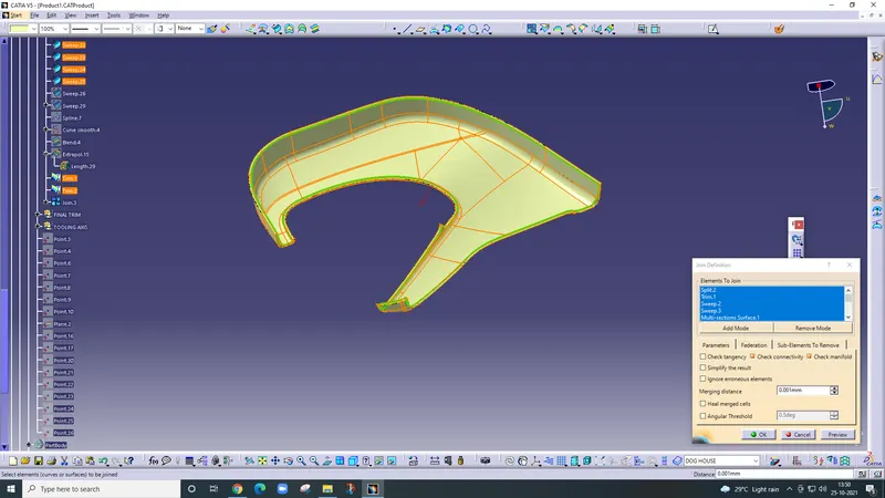
join the class A surface and C surface.
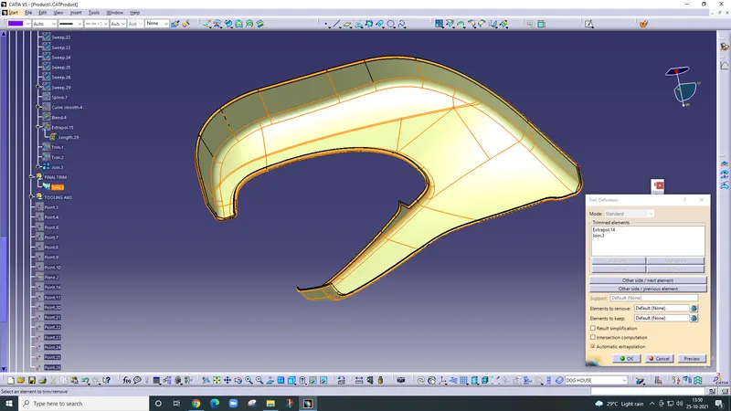
trim the B surface and c surface using the trim command.
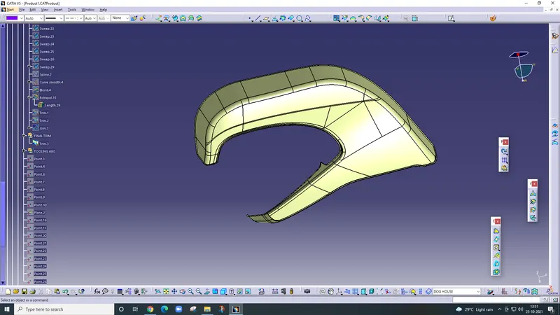
Draft analysis in the lower substrate.
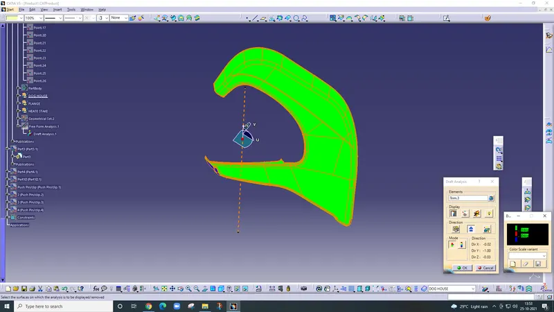
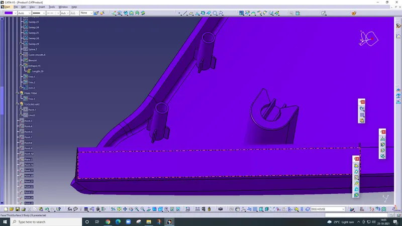
Adding the flange on the lower substrate.
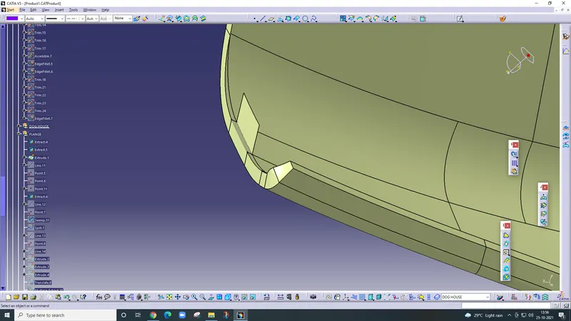
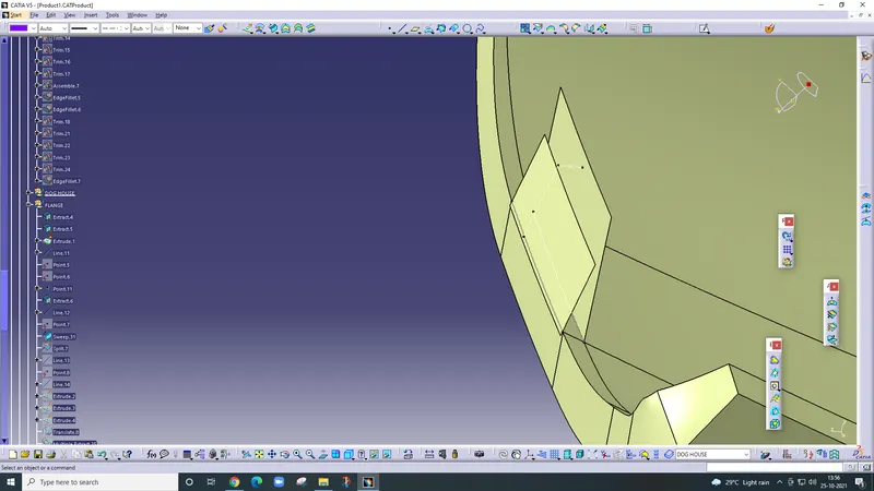
Extract the surface and extrude the line and sweep the line.
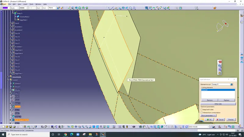
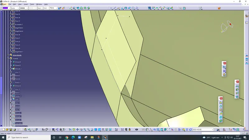
trim the extra part.
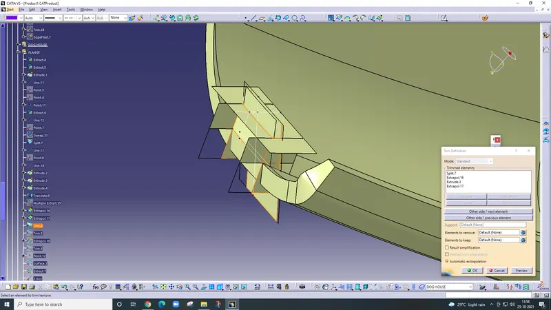
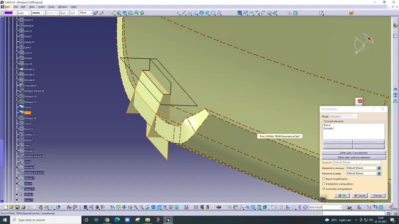
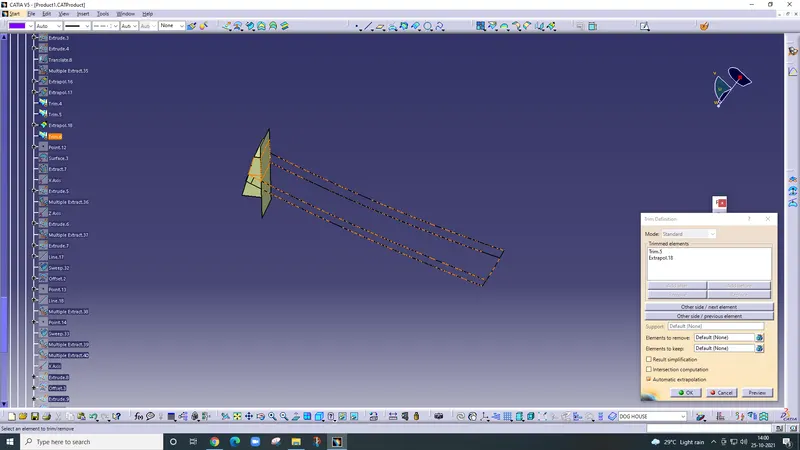
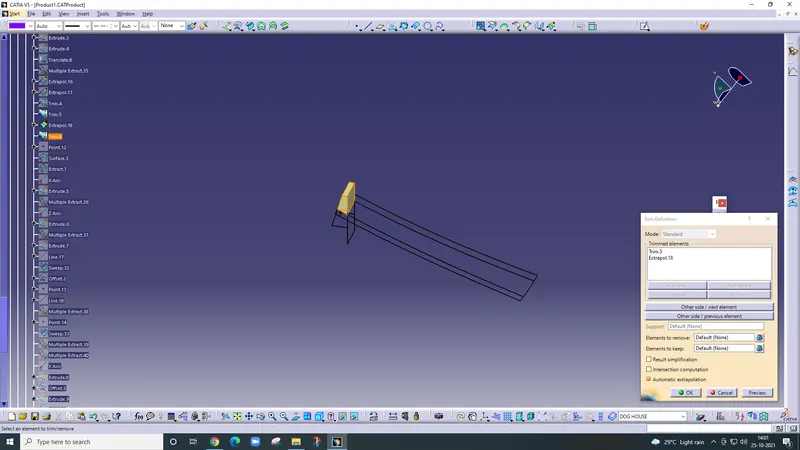
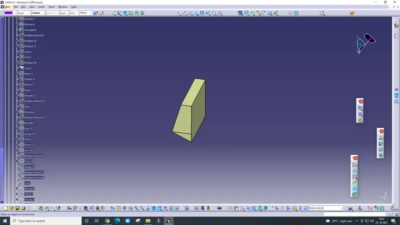
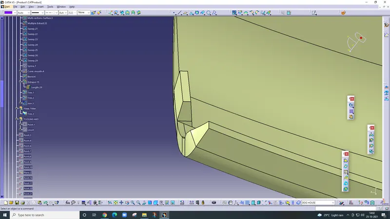
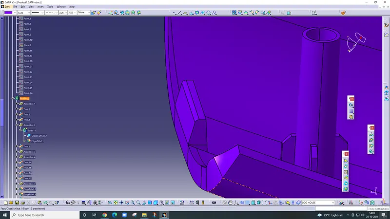
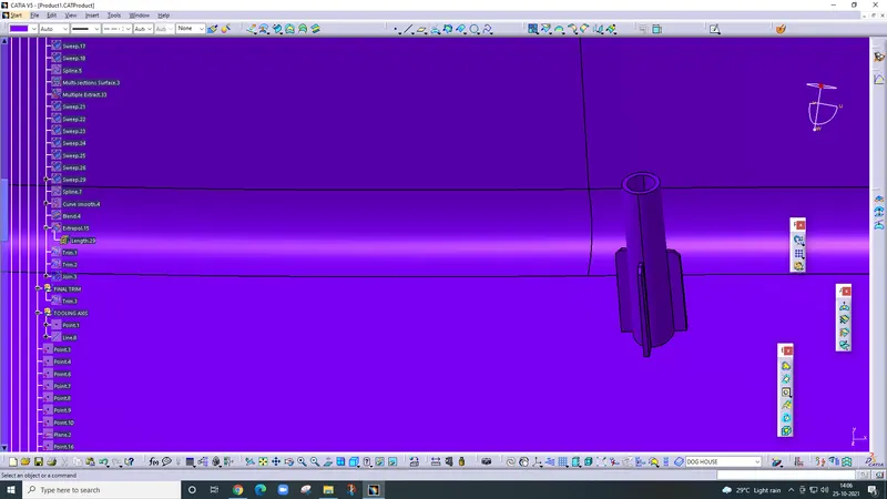
also added a heat stake and dog house on the lower substrate.
Dog house -
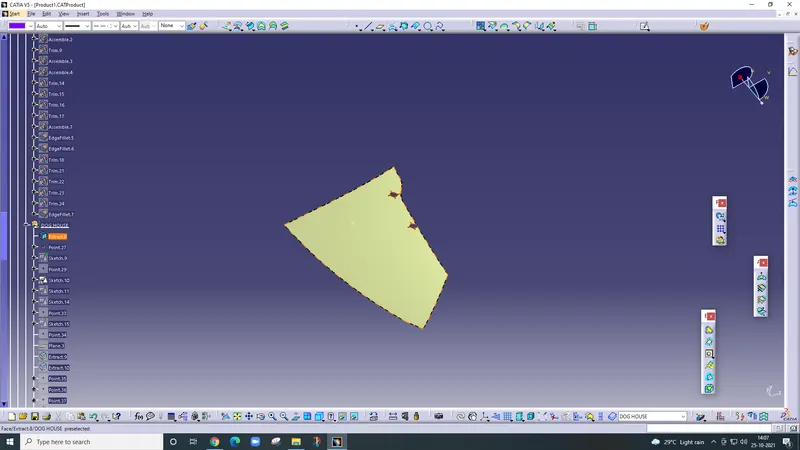
The main function of the Dog house is to avoid sink marks.
The rules to be followed to create a dog house are:
- Minimum height of 6mm or less.
- Width ratio 3:1
3. Minimum draft of 1.5deg.
- C value should be 40% of the nominal thickness i.e 3 to 6mm.
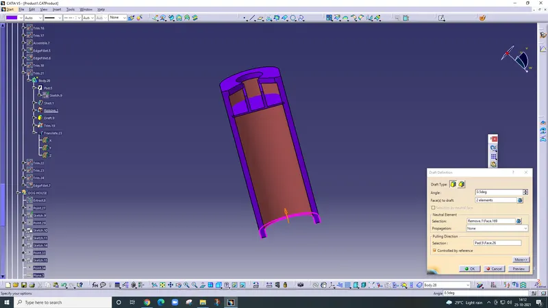
extract the surface and then draw the sketch on it after that pad it then shell it.
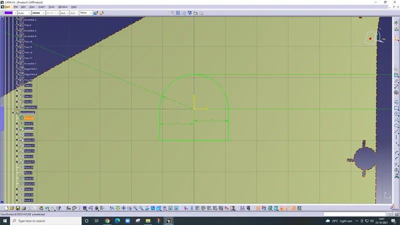
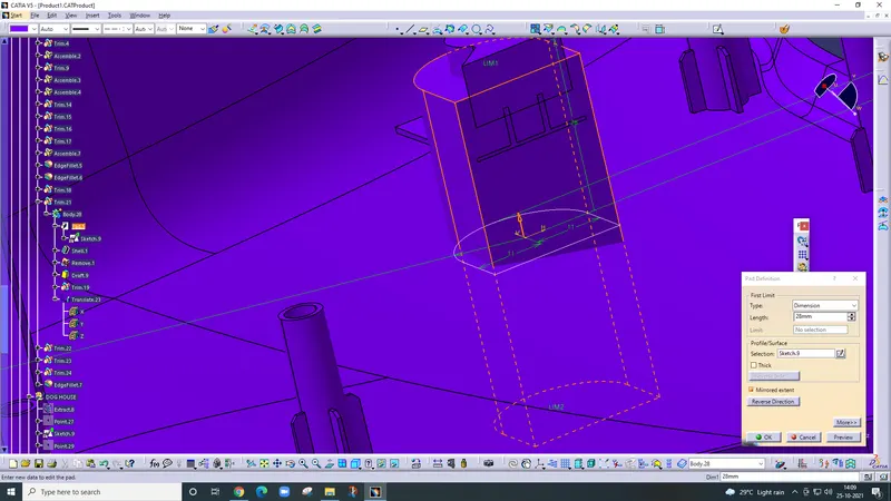
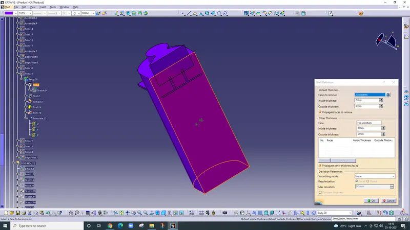
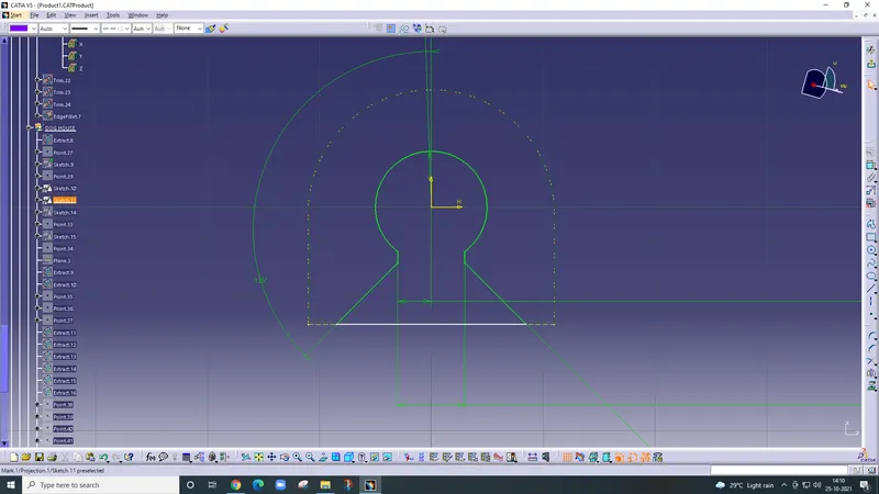
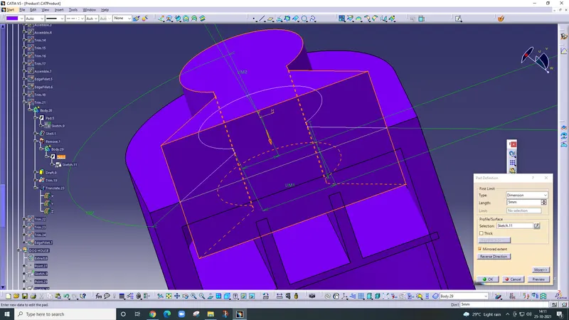
Draw the profile on top then pad on both sides and then remove it.
Draft angle
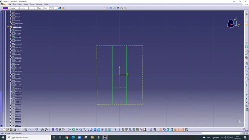
then added the rib and then pad it after that extra part is untrim.
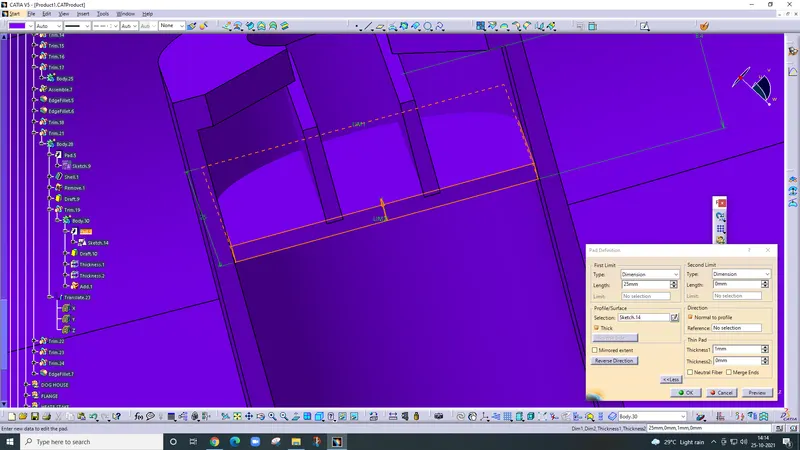
Draft angle
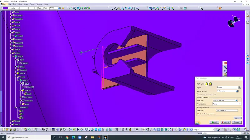
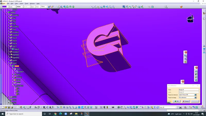
Translate the dog house.
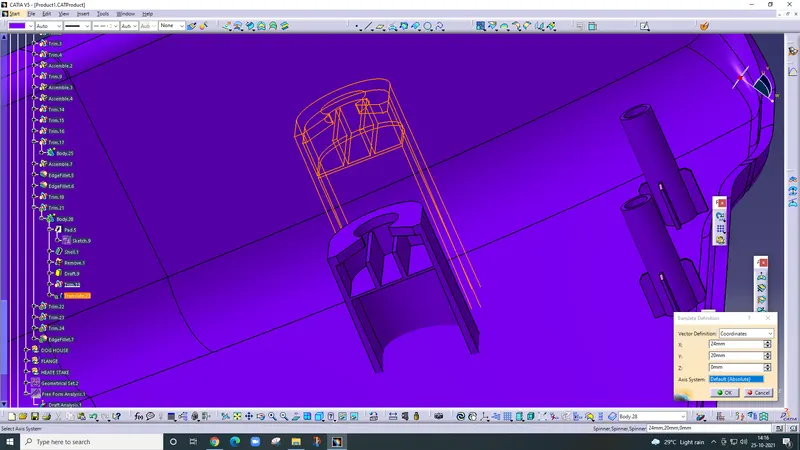
untrim the extra part.
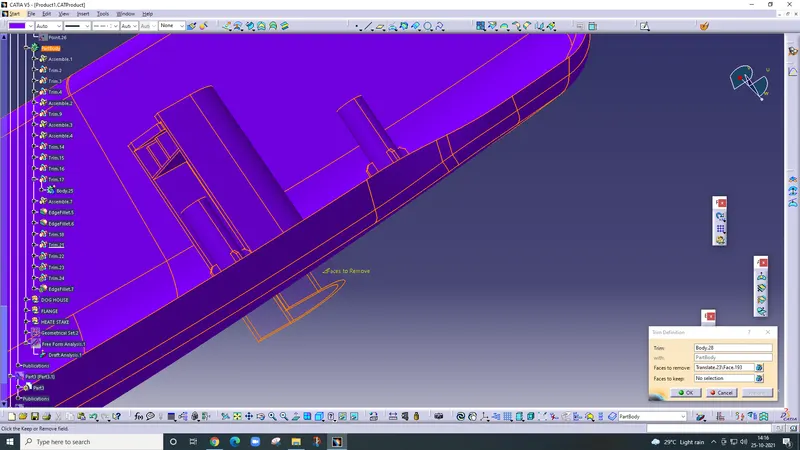
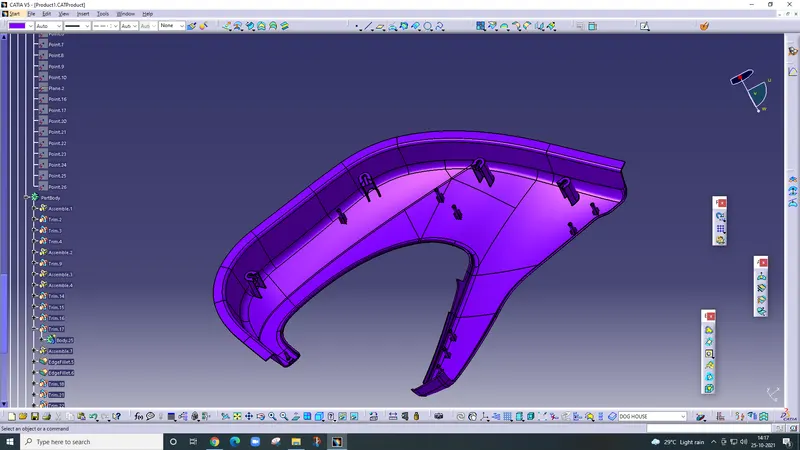
Draft analysis.
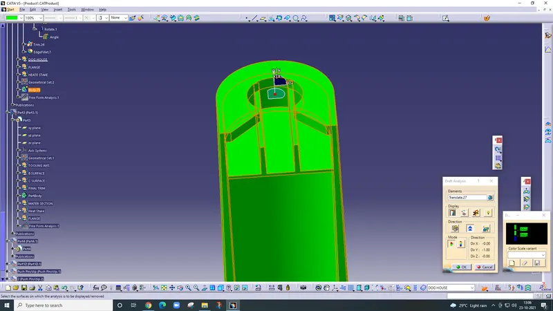
added the outside flanges
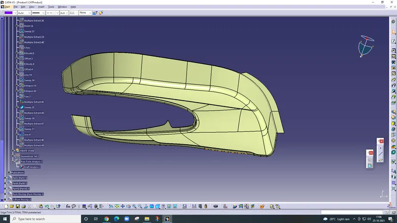
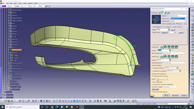
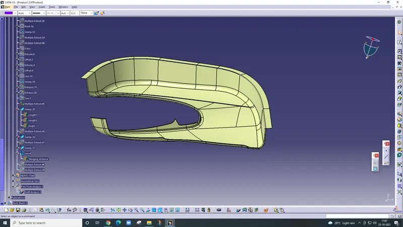
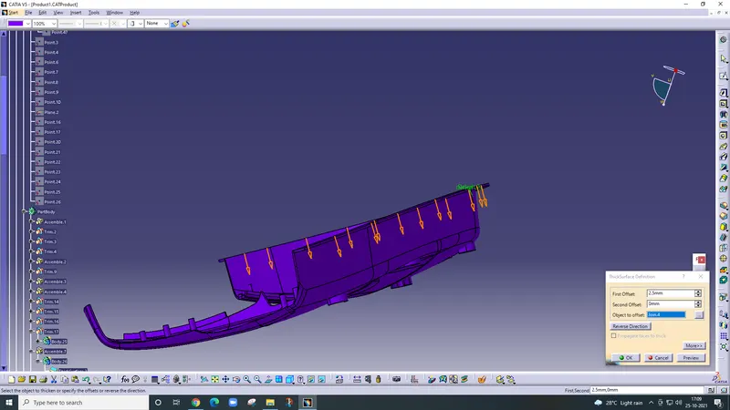
thick the flange up to 2.5mm.
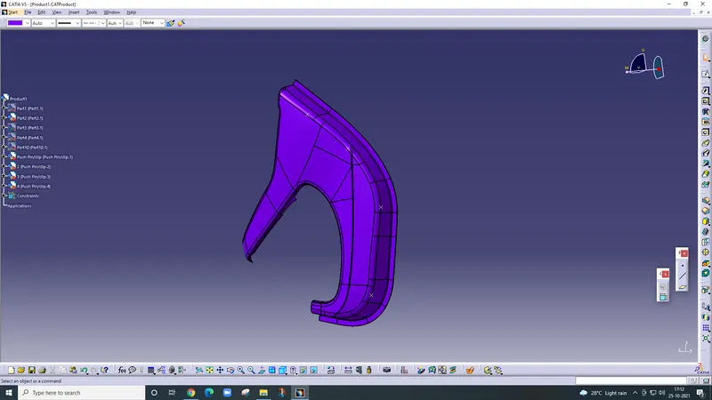
Assemble the pushpin in the dog house.
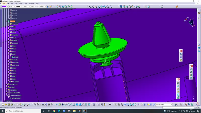
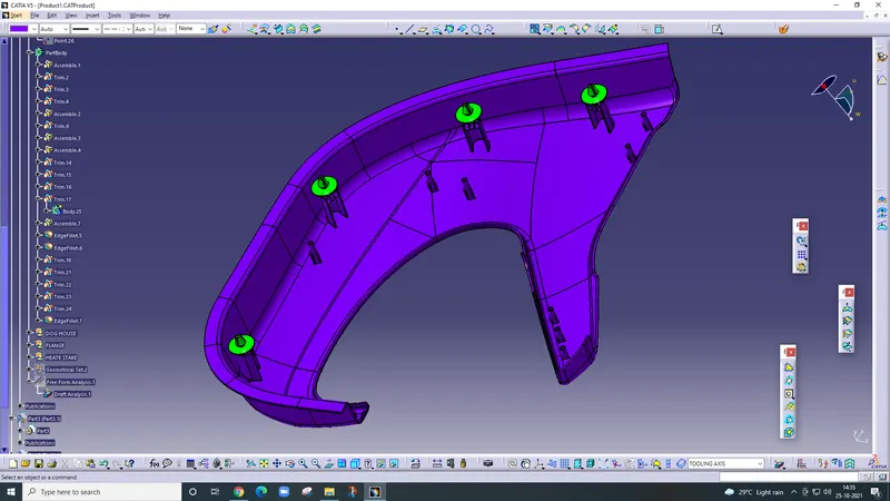
final component.