Week 11 - Final project
Development of a Door Trim panel
Objective -
To develope a door trim panel containing Arm rest ,lower substract,map pocket and bottle holder using Class A and masters sections as input. the design and developement is done using catia v5 software with implementation of concepts and rules of plastic product design.
The components has to be developed as per the Design for Manufacturing and Assembly (DFMA), these are the rules used by industries. these rules define that the designed products are manufactured by injection moulding or any methods.
Some of the rules include constant part thickness, draft direction, draft analysis, parting line, parting surface, B- surface creation, C- surface creation, draft analysis on the part, B-side features like locators,dog house, screw boss,ribs, heat stakes and flanges for assembly fitment.
Introduction -
Door panels serve as an interface between the interior of the car and the inner workings of the door, and between vehicle occupants and the door. They are expected to meet a variety of design specifications regarding safety, aesthetics, and functionality. In addition, they are expected to continue the material theme of the dashboard and pillars while concealing intricate electrical and mechanical components for operating locks, windows, and other features.
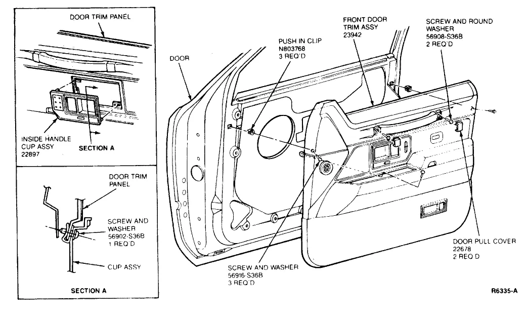
project -
Development of a Door Trim panel.
Creation of CAD model with Class A surface and master sections as reference, by using assembly approach, in this project we are going to use top down approch in assembly approach ie. we will get the class a surface in the form of the assembly format then we need to creat each part by using the new part command which is present in the product structure tools which is present in assembly work bench, we need to repeat the same procedure the remaining parts like lower substract, map pocket , arm rest ,bottle holder, etc... and for the push pin we need to follow the bottom to top approach ie. we need to use excisting component to open a new part in the assembly work bench and then we need to work on them.
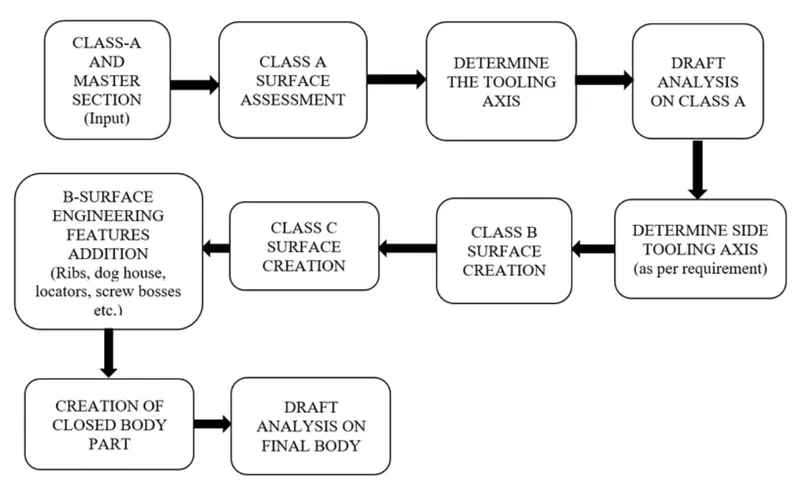
class A-surface -
Class A is
1.Visible surface and aesthetic look
2.surface with textures
3.Surfaces provided by customer(OEM)
4.Don't have any features like(rib,snap,bosses etc) on class A surface.
5.Class A surface is made from scanned data with different software like allias etc..
6.Surfaces which is having CURVATURE CONTINUITY IS CALLED class-A.
Class B-surface-
Class B surface:
1.invisible Surfaces.
2.Surface mostly don't have textures
3.Surface need to be create according to class-A surface.
4.having all features(Rib,boss,snap etc) in B-side surface only.
5.Surfaces which is having TANGENT CONTINUITY IS CALLED class-B
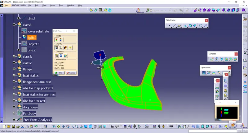
Draft analysis-
- Before starting to work on the part we have to see the connectivity of class A (the give input is closed or not )(use join)
- In order to creat a tooling axis we have to creat lines in x-direction and y-direction and we have to bisect them to get the tooling axis .
- We have to take the axis system at the center of the surface (calss A) and we have to intersect them with xz directon of the planes . so that we get wire frame in the desired
direction in which we have to creat lines and bisect them . so the lines we get after the bisection it is known as tooling axis .
we have to do this for the other direction (or )plane also . - After getting the tooling axis we need to publish them . (tools - publication - select on the requid elements).
- In order to do the draft analysis we need to change the material , which is present in . view tool bar . (view tool bar - cylinder - click the last cylinder) .
- a window will open ,click on material then ok .
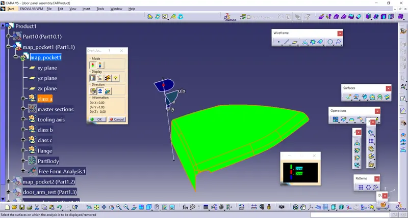
- To open draft analysis , go to (insert - analyis - draft analysis )
- After opeaning the draft analysis tool
we have to click on the compass which is oresent in draft analysis table and find the compass , drag it towards the tooling axis and design them .
click on the lock box then ("x") thhis symbol will arise , go to the object and click on them .
we can measure the angle of object by clicking on the eye symbol which is present on the display .
we can get the result by clicking options which are present on the model .
Creation of class A surface -
- from the given class A surface first we need to see there are any errors like patches, double boundaries, irregurlar surfaces etc...
- to rectify these kind of errors we need to use boundary tool to see there are any unwanted boundaries and hence if there we need to clear them.
- hence the surface is cleened up we need to extract the given class a surface by using offeset tool. here we need to offset with out giving the any distance and hide the original class A surface.
- now from the master section 2 we observe that we need to there is a flange which is a engineering feature.
- to create the flange we need to extract the side boundary of the class a surface then we need to extract the adjacent side after the extract is taken we need to use sweep tool (with reference surface), by using this tool we will get the flang surface. note we have to choose the correct angle with the help of the master section 2.
- since we get the flange for one side there for we need to follw the same procedure to the other side also. after getting the two flanges we need to combine them with the class A surface. by doing this we will get class A surface for the B-piller.
Creation of class B surface-
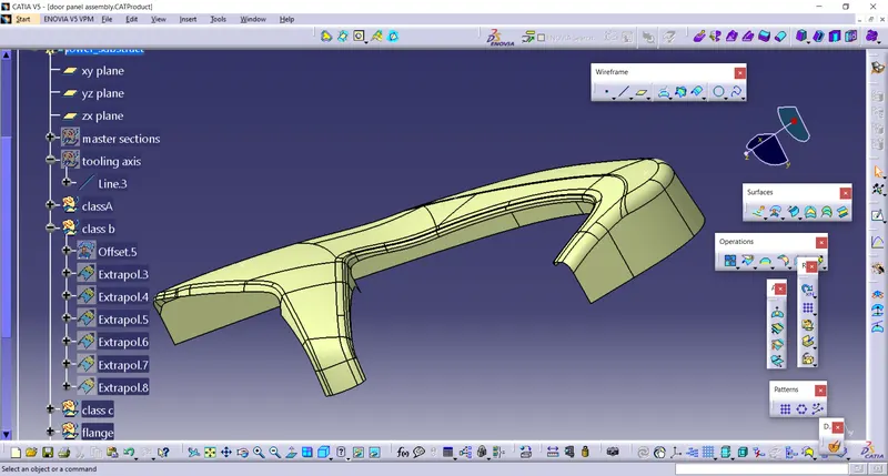
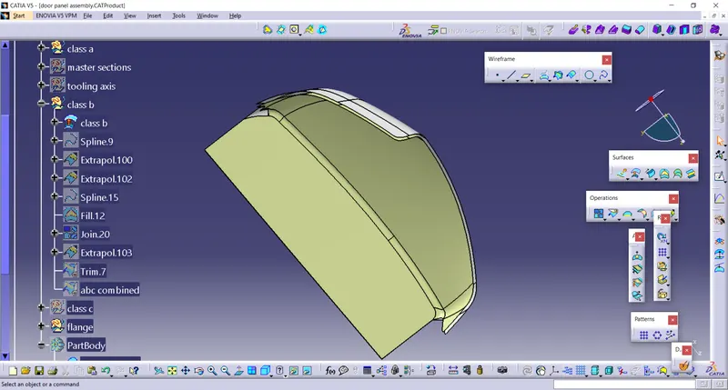
- For the creation of the class b surface we are going to use the class A surface which we developed, now we are going to use the off-set tool then we have to give the distance from which we need to get the off-set from the class a surface, to find the distance we need to measure the distance in the master section 2.
- After giving the distance we need to give the direction to the off-set(we haveto give the direction towards in side).
- Since the off-set towards the inside is done, because of the compressionof the surface takes place there will be missing of some surfaces we need to re-create these surfaces with the help of the tools like extract,spline,fill and multi-section solid. there by the class b surface is created.
- Then we need to extend the boundaries of the class b surface by using the extrapolate tool.
Creation of class C surface-
Creation of Class C Surface and converting it into solid -
- For the creation of class c surface we need to use class a boundary.
- After getting the boundary we need to use the sweep tool to get the class c surface. in the sweep tool (with reference surface), by using this tool we will get the class c surface. for the reference surface we need to give the class A surface as the reference surface then for the angle we need to give the angle fo the master section 2.
- we need to sweep the boundary one by one and final we need to combine them with trim tool. hence we get the class c surface.
- After getting the three surfaces we need to combine them with trim tool.
- Now we have to go to the apart worke bench and we have to use close solid tool to get a solid part.
The door panel project is mainly divided into five parts they are as follows ie. lower substract, map pocket, bottle holder and arm rest .
lower substract -
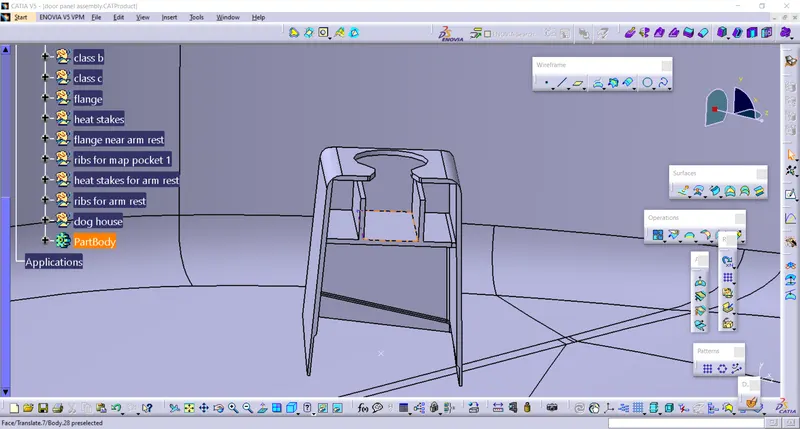
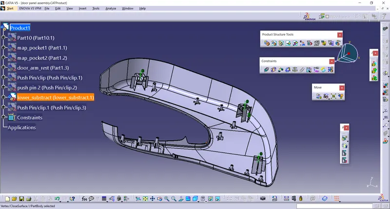
The lower substract has the larger area in the dood panel and the B side features like locators,dog house, screw boss,ribs, heat stakes and flanges lies on it .
Class A surface of lower substract
Draft analysis on class a surface -
Class B surface of lower substract-
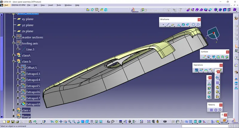
Class C surface of lower substract -
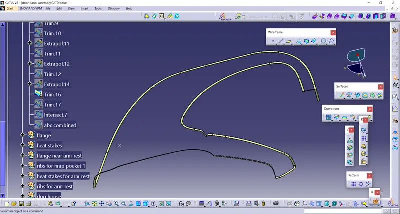
Solid part of lower substract-
B side features on lower substract -
Map pocket -
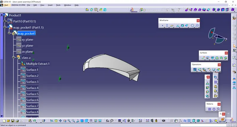
Class A surface of Map pocket -
Draft analysis of class A surface of map pocket -
Class B surface of map pocket -
Class C surface of map pocket -
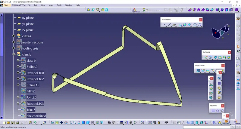
Combined surface of map pockets -
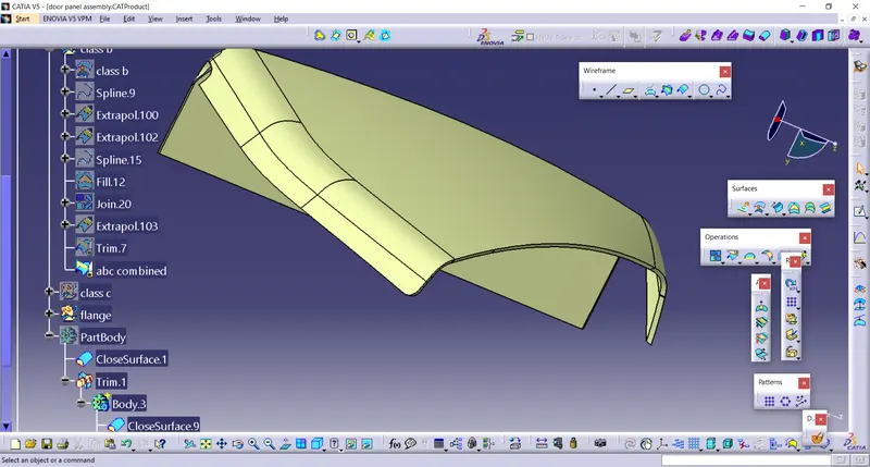
Image showing solid body of map pocket-
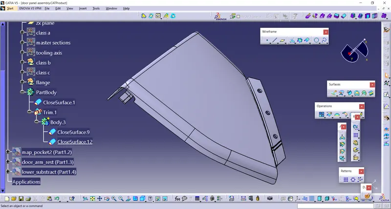
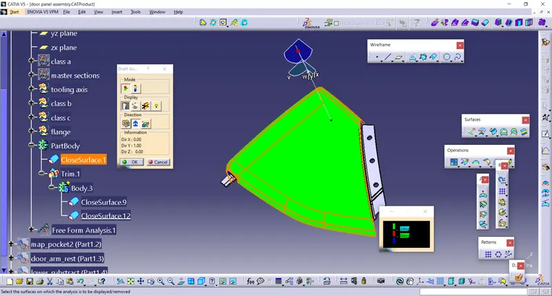
Draft analysis of part body and engineering features -
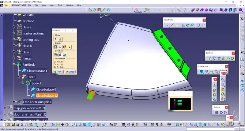
Arm Rest
Class A Surface of Arm rest -
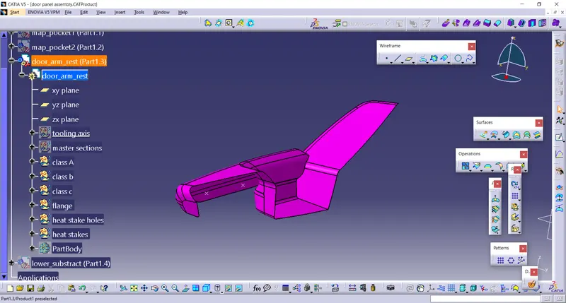
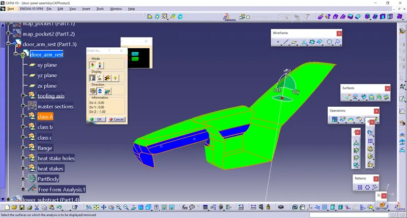
Draft analysis of class A surface-
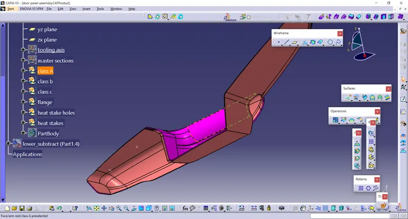
Class B surrface of arm rest-
Class C surface of arm rest-
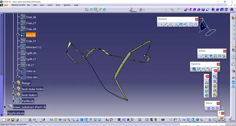
Combined surfaces of arm rest -
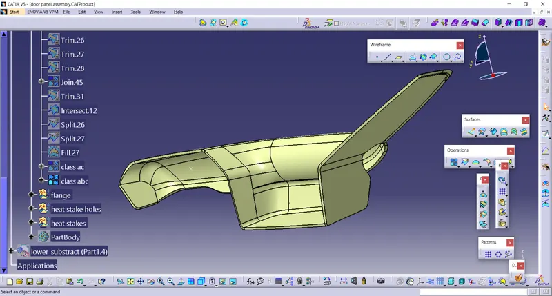
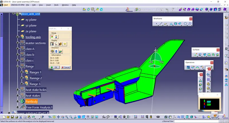
Draft anslysis of solid body -
Bottle Holder
Class A surface of Bottle Holder-
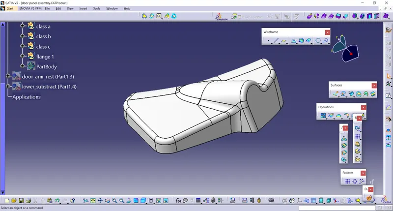
Draft analysis of class a surface of Bottle Holder-
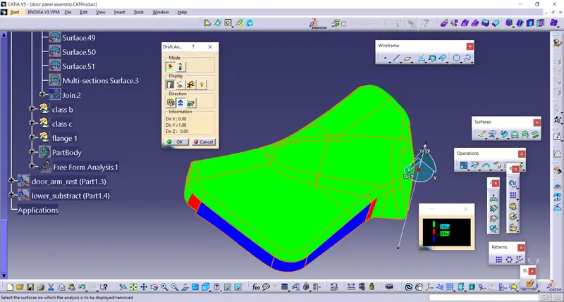
Class b surface of Bottle Holder-
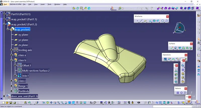
Class c surface of Bottle Holder-
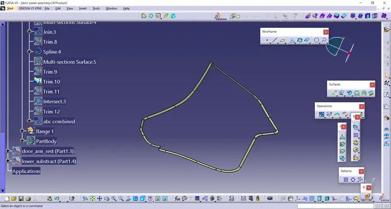
Combined surfaces of Bottle Holder-
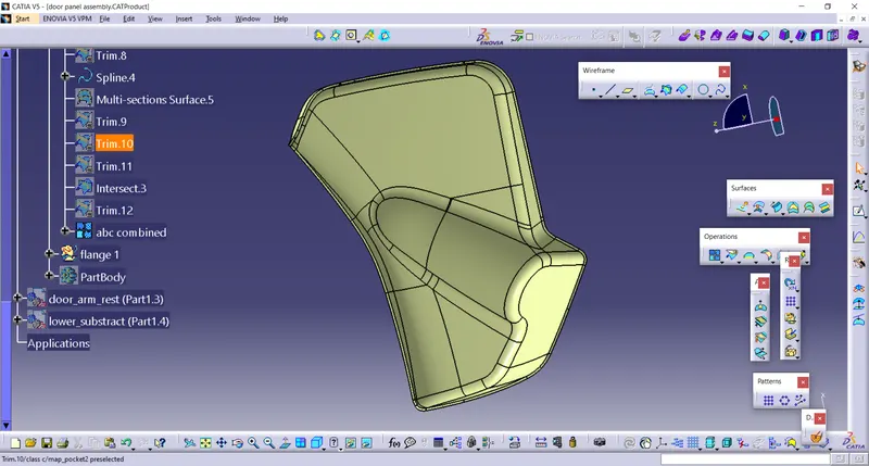
Draft analysis of solid body with flanges -
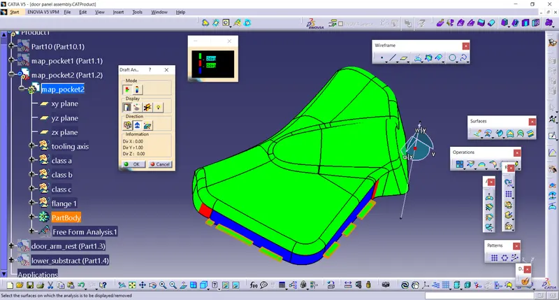
Push pin
Image showing push pin-
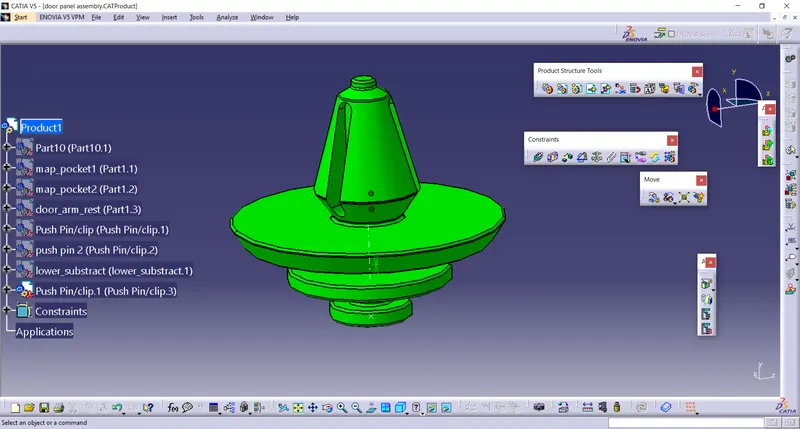
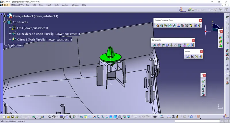
Image showing dog house with push pin -
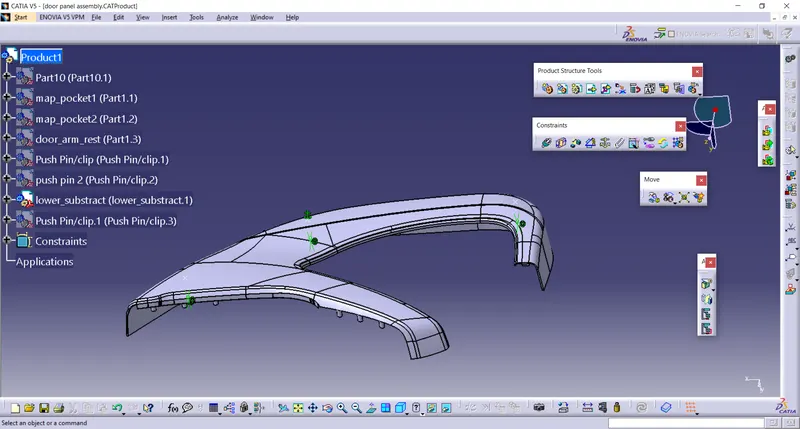
Door panel Assembly -
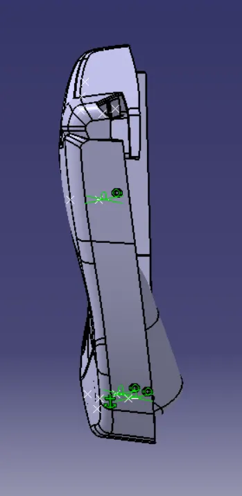
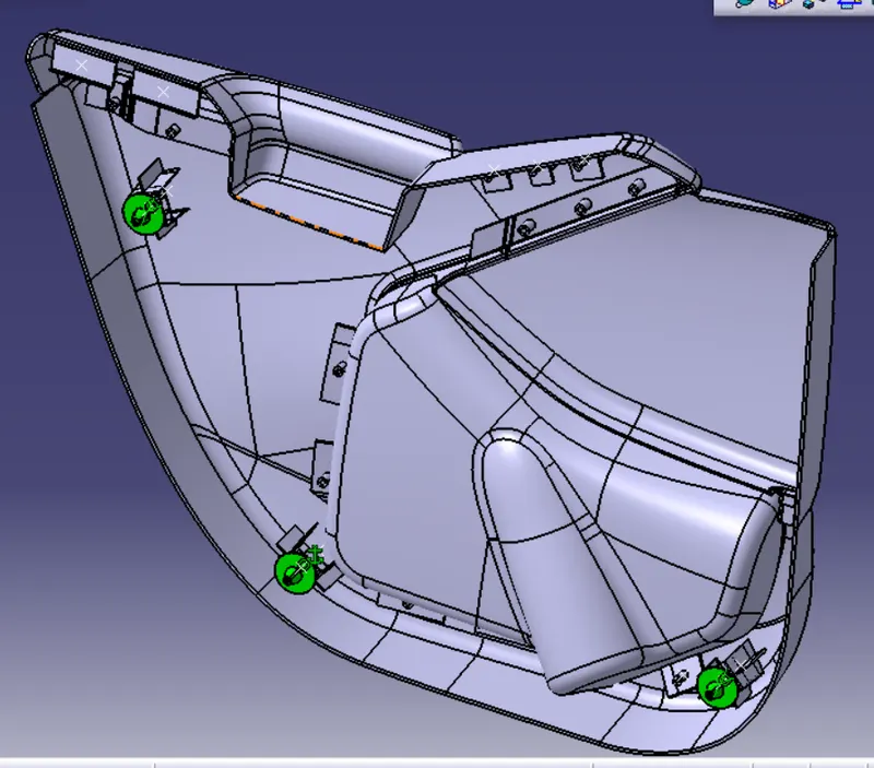
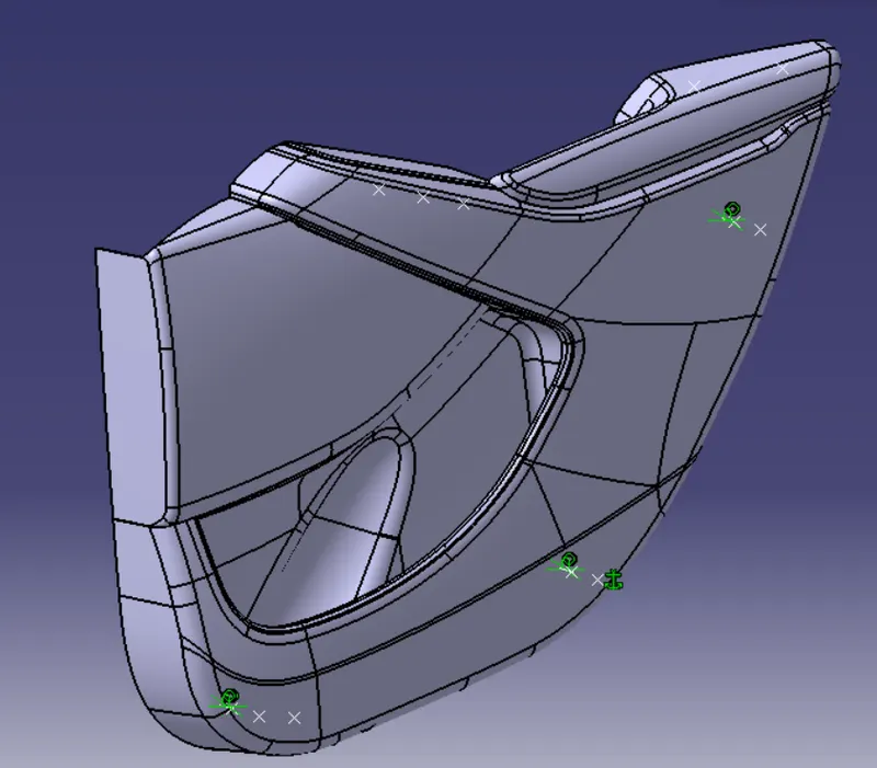
Image showing the complete door panel assembly with b side features-
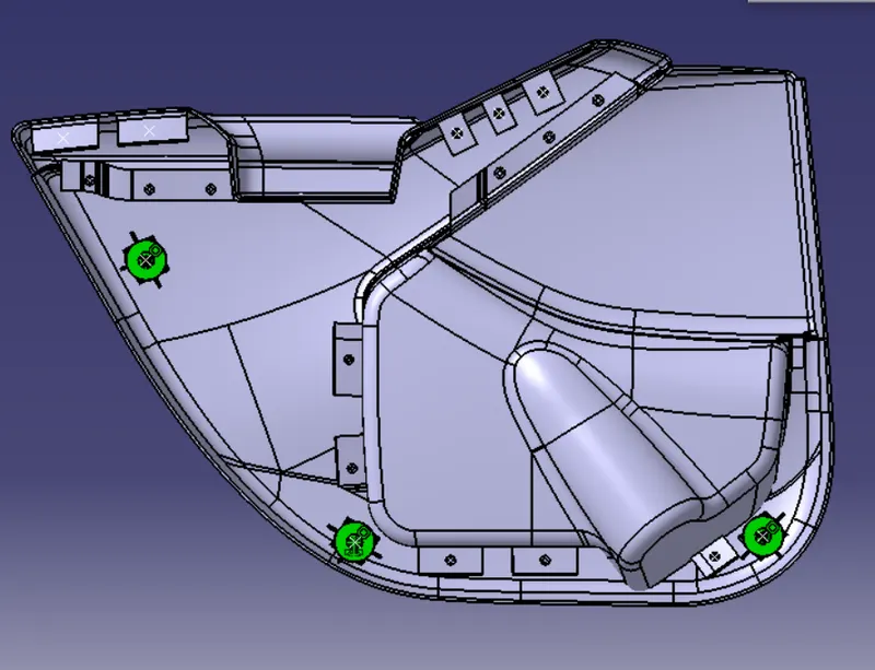
Saving the Assembly File -
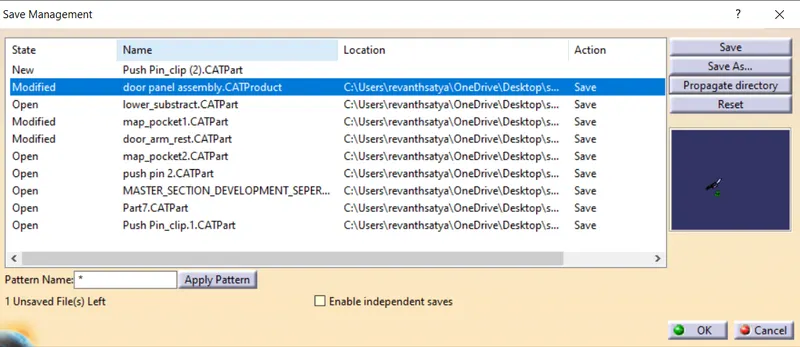
To save the assembly we need to click on the file option and go to save management and click on the product and we need to do save as option and then we need to use propegatr directory and save the assembly.
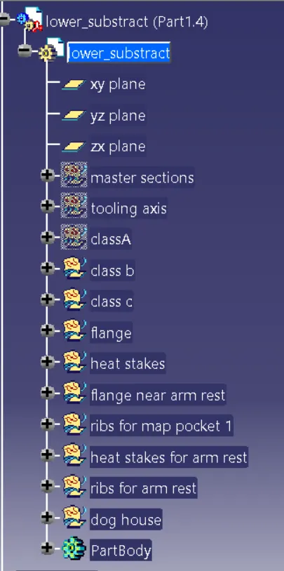
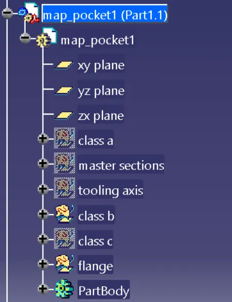
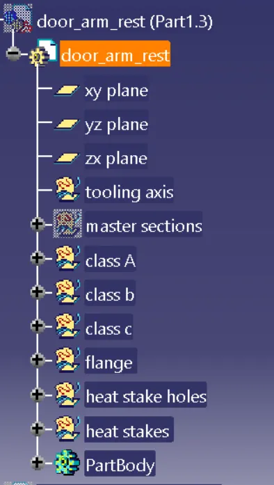
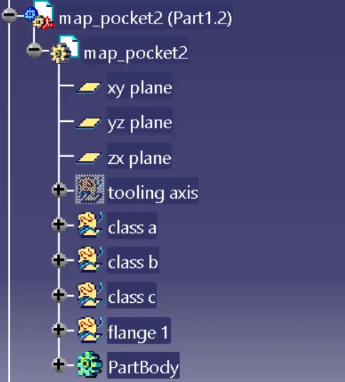
Tree diagrams for each part -